HAL Id: hal-02306951
https://hal.telecom-paris.fr/hal-02306951
Submitted on 7 Oct 2019
HAL is a multi-disciplinary open access
archive for the deposit and dissemination of sci-entific research documents, whether they are pub-lished or not. The documents may come from teaching and research institutions in France or abroad, or from public or private research centers.
L’archive ouverte pluridisciplinaire HAL, est destinée au dépôt et à la diffusion de documents scientifiques de niveau recherche, publiés ou non, émanant des établissements d’enseignement et de recherche français ou étrangers, des laboratoires publics ou privés.
Narrow spectral linewidth in InAs/InP quantum dot
distributed feedback lasers
J. Duan, H. Huang, Z. Lu, P. Poole, C. Wang, F. Grillot
To cite this version:
J. Duan, H. Huang, Z. Lu, P. Poole, C. Wang, et al.. Narrow spectral linewidth in InAs/InP quantum dot distributed feedback lasers. Applied Physics Letters, American Institute of Physics, 2018, 112 (12), pp.121102. �10.1063/1.5022480�. �hal-02306951�
Narrow spectral linewidth in InAs/InP quantum dot distributed feedback lasers
J. Duan, H. Huang, Z. G. Lu, P. J. Poole, C. Wang, and F. GrillotCitation: Appl. Phys. Lett. 112, 121102 (2018); doi: 10.1063/1.5022480 View online: https://doi.org/10.1063/1.5022480
View Table of Contents: http://aip.scitation.org/toc/apl/112/12
Narrow spectral linewidth in InAs/InP quantum dot distributed feedback
lasers
J.Duan,1,a)H.Huang,1Z. G.Lu,2P. J.Poole,2C.Wang,3and F.Grillot1,4 1
LTCI, T!el!ecom ParisTech, Universit!e Paris-Saclay, 46 rue Barrault, 75013 Paris, France
2
Advanced Electronics and Photonics Research Centre, NRC Canada, 1200 Montreal Road, Ottawa K1A 0R6, Canada
3
School of Information Science and Technology, ShanghaiTech University, Shanghai 201210, China
4
Center for High Technology Materials, University of New-Mexico, 1313 Goddard SE, Albuquerque, New Mexico 87106, USA
(Received 15 January 2018; accepted 12 March 2018; published online 23 March 2018)
This paper reports on the spectral linewidth of InAs/InP quantum dot distributed feedback lasers. Owing to a low inversion factor and a low linewidth enhancement factor, a narrow spectral linewidth of 160 kHz (80 kHz intrinsic linewidth) with a low sensitivity to temperature is demonstrated. When using anti-reflection coatings on both facets, narrow linewidth operation is extended to high powers, believed to be due to a reduction in the longitudinal spatial hole burning. These results confirm the high potential of quantum dot lasers for increasing transmission capacity in future coherent communi-cation systems.Published by AIP Publishing.https://doi.org/10.1063/1.5022480
With the growing requirement for transmission capacity in optical communication systems, coherent technology has been attracting more and more attention.1A coherent system is able to restore both the amplitude and phase information of optical signals but remains very sensitive to the phase noise of both the transmitter and the local oscillator. In order to reduce the noise in the detection part, local oscillators with low phase noise are required. Indeed, although the fre-quency drift of the transmitter can be minimized, the carrier phase still fluctuates randomly because of the phase noise induced from the lasers. Therefore, a local oscillator with a narrow spectral linewidth is a crucial requirement for realiz-ing stable heterodyne detection. Aside from the linewidth, such lasers must also be single-frequency, energy efficient, and monolithically integrable.2 To meet these goals, semi-conductor distributed feedback (DFB) lasers with strained quantum well (QW) layers have been touted to be very reli-able single wavelength sources.3,4However, most QW DFB lasers made with simple grating designs usually exhibit spec-tral linewidths of a few MHz.3,5The main reason for such a broad spectral linewidth is due to the short optical cavity and weak internal feedback, leading to a lowQ-factor that is the ratio of the energy stored by a cavity to the power lost. Thus, in order to reach a kHz spectral linewidth, continuous efforts have been made to decrease the spontaneous emission rate into the lasing mode or to increase theQ-factor and hence the number of photons stored in the cavity. Therefore, differ-ent designs of single-mode devices have been proposed to achieve narrow linewidths on the order of 100 kHz or below, such as external cavity,6phase-shifted and chirped grating,7,8 discrete mode DFB lasers,9and fiber lasers.10 In particular, one recent solution was obtained from a proper modal engi-neering of a DFB laser in which light is generated in the III–V material and stored into the low-loss silicon material. Fabricated lasers using modal engineering to concentrate light in silicon unveil spectral linewidths five times smaller
than any other semiconductor lasers.11 Although the
afore-mentioned techniques can satisfy the ultra-narrow linewidth and power requirements, they require either more complex technologies or remain significantly bulky with poorer mechanical stability as opposed to standard DFB lasers which can be manufactured in large numbers and at low-cost. Additional breakthroughs can be achieved by using a gain medium made with self-assembled quantum dots (QDs) from which the shape of the density of states, as well as the carrier confinement, does substantially improve the laser per-formance.12,13 Indeed, advances in crystal growth have led to high quality 1.55lm semiconductor lasers operating with gain regions containing either QDs or quantum dashes.14,15 By doing so, spectral linewidths between 200 and 500 kHz have been reported on both InAs/GaAs and InAs/InP QD lasers.16,17 Very recently, a spectral linewidth as low as 110 kHz has been demonstrated in an InAs/InP QD DFB laser.18
The spectral linewidth of semiconductor lasers is expressed by the modified Schawlow-Townes expression19
D! ¼Cgthv 2 gamh! 4pP0 nsp 1þ a2H ! " ; (1)
whereCgthis the modal gain at threshold,amthe mirror loss,
h! the photon energy, P0the optical output power, nsp the
inversion factor, and aH the linewidth enhancement factor
accounting for the coupling between the carrier-induced var-iation of real and imaginary parts of the effective susceptibil-ity. From Eq. (1), the aH-factor appears as an additional
mechanism of phase fluctuations responsible for the much broader linewidth in semiconductor lasers.20Therefore, nar-row linewidth lasers should be designed to minimize the effect of theaH-factor. On the other hand, the need to pump
the semiconductor to optical transparency creates a mini-mum carrier density and current at threshold. The inversion factor nsp accounts for this minimum carrier density in the
laser, applying a penalty for incomplete inversion. In QW
a)Electronic mail: [email protected]
0003-6951/2018/112(12)/121102/5/$30.00 112, 121102-1 Published by AIP Publishing.
lasers,nspis typically in the range from 1.5 to 2.5, while it is
much lower in QDs owing to the smaller number of carriers required to reach the transparency.21Therefore, the quantity nsp# ð1 þ a2HÞ should be used as the figure of merit of
nar-row linewidth operation rather than the soleaH-factor.5
In this paper, we perform a systematic investigation of the spectral linewidths of InAs/InP QD lasers emitting at 1.52lm. A narrow spectral linewidth of 160 kHz (80 kHz intrinsic linewidth) with a low temperature dependence is demonstrated in a DFB laser with asymmetric facet coatings. The temperature behavior is also confirmed by simulation. The influence of the spatial nonlinearities originating from the longitudinal spatial hole burning (LSHB) on the spectral linewidth is also studied. By using a DFB laser with symmet-ric facet coatings, results show that narrow linewidth opera-tion can be further extended at high powers.
The QD lasers under study were grown by chemical beam epitaxy (CBE) on a (100) oriented n-type InP substrate. The undoped active region of the laser consisted of 5 stacked layers of InAs QDs with 30 nm In0.816Ga0.184As0.392P0.608
(1.15Q) barriers. The QDs were tuned to operate in the desir-able operation wavelength range by using a QD double cap growth procedure and a GaP sublayer.15Growing the dots on a thin GaP layer allows a high dot density to be obtained and improved layer uniformity when stacking multiple layers of dots, providing maximum gain. Photoluminescence (PL) from a 5 QD layer test structure grown just before the laser had a full-width at half-maximum (FWHM) of 36.5 meV at 4 K which broadened to 60 meV at 300 K, indicating good dot size uniformity. This active layer was embedded in a 350 nm thick 1.15Q waveguiding core, providing both carrier and optical confinement. An average dot density of approxi-mately 4# 1010cm&2 per layer was obtained according to atomic force microscopy (AFM) measurements on uncapped stacked dot samples.
Following the growth of the QD active core, the wafer was removed to pattern the grating region. This was per-formed using a HeCd laser to holographically expose an optical resist with a uniform grating pattern across the whole wafer, followed by wet chemical etching. After the pattern-ing of the gratpattern-ing, the p-type InP claddpattern-ing and InGaAs con-tact layers were regrown using metal-organic chemical vapor deposition (MOCVD). The wafer was PL mapped before and after regrowth by MOCVD, and no change was observed in the PL emission wavelength, indicating the high material quality of both growth steps.22
Single lateral mode ridge waveguide lasers were fabri-cated with a stripe width of 3lm and a cavity length of 1 mm. Both facets were coated to modify the reflectivity of the laser cavity. One laser used a very low reflectivity antire-flection coating (AR) on both facets (<0.01%) to remove the effects of the termination phase of the grating at the cleaved facets,23 and this laser is referred to as the AR/AR design. The other laser used asymmetric facet coatings, with the out-put facet having a 2% reflectivity, while the rear facet having a reflectivity of 62%, which is referred to as the AR/HR design. The AR/HR design is much more sensitive to the grating phase at the facets, and since the grating used was uniform, i.e. there were no phase shifts introduced, this meant that different devices were observed lasing on the
short wavelength side of the DFB stopband, the long wave-length side, and both sides simultaneously. For the AR/AR design, all the laser devices emitted on the short wavelength side of the stopband for all drive currents, a consequence of spatial hole burning in a symmetric device with a uniform grating.23The devices under study in this work emitted only at a single wavelength.
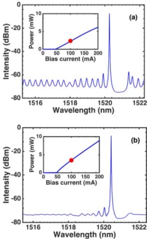
Figure1shows the single-mode lasing spectra for both devices (at 100 mA), which exhibit lasing wavelengths at 1.52lm and side mode suppression ratios (SMSRs) of at least 50 dB over the whole current range. The insets display the corresponding L-I curves, with threshold currentsIthof 46 mA
for the AR/HR device and of 47.5 mA for the AR/AR device. Fabry-Perot (FP) ripples are observed outside the grating stop-band in the AR/HR device, while those disappear in the AR/ AR device owing to the smaller facet reflectivities. The grat-ing couplgrat-ing constant j was measured to be 10 cm&1 deter-mined from the laser spectra just below threshold, leading to a value forjL of 1, with L being the length of the laser cavity.
The material aH-factor is extracted from the amplified
spontaneous emission (ASE).24To do so, a FP cavity is con-sidered because the ASE method is not easily applicable to DFB lasers for which the grating makes the gain extraction more complicated. The experimental procedure for retrieving the aH-factor is fully detailed elsewhere.24 Figure 2depicts
the measured aH-factor as a function of the lasing
wave-length. Values ranging from 0.7 to 2.2 are obtained over a span of 50 nm. At the FP gain peak (1545 nm), a relatively low value of 1.4 is obtained. Note that the aH-factor quoted
FIG. 1. Optical spectra measured at 100 mA (red markers) for (a) the AR/ HR DFB laser and (b) the AR/AR DFB laser. The insets show the corre-sponding light current curves.
in Fig.2is only valid for the FP laser which does not suffer from strong LSHB. As such, it cannot be used for analyzing theaH-factor of DFB lasers under study except at low drive
currents (i.e. not too far from the threshold) where the LSHB remains small.
Figure3shows the self-heterodyne interferometric appa-ratus used to measure the spectral linewidth.25Once the laser emission is launched into the fiber interferometer, part of the signal is sent to a 100 MHz frequency-shifted acousto-optic modulator (AOM), while the other part propagates through a 25 km fiber coil. The polarization controller is used to match the polarizations in the two arms. At the output of the inter-ferometer, the resulting beat note centered at the AOM fre-quency is recorded with the photodiode (PD) and sent to the electrical spectrum analyzer (ESA). Two optical isolators, of more than 60 dB isolation, were used to eliminate the reflected light. Experimentally, the total spectral linewidth is broadened, hence corresponding to a Voigt profile which is mathematically a convolution of a Lorentzian lineshape rep-resenting the intrinsic laser linewidth with a Gaussian line-shape accounting for the technical noise (current noise and thermal fluctuations). In what follows, measured spectra are curve-fitted using the pseudo-Voigt approximation that relies on using a linear combination of Gaussian and Lorentzian profiles rather than the convolution.26
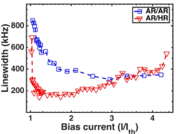
Figure 4illustrates the spectral linewidths fitted with the pseudo-Voigt profile as a function of the normalized drive cur-rent I/Ith, for the AR/HR (red) and the AR/AR lasers (blue). For
the AR/HR DFB laser, a minimum linewidth of 160 kHz is reached atI/Ith¼ 1.7 with a fitted intrinsic Lorentzian linewidth
as low as 80 kHz which is smaller than that of 110 kHz.18Note
that similar results are obtained with a pure Voigt profile. From Eq.(1), the threshold gain is calculated by taking into account the loss induced by the grating that is about 6 cm&1, which contributes to a modal gain at a threshold of about 19 cm&1. Then, the physical quantity nsp# ð1 þ a2HÞ is
esti-mated to be about 1.4 at an output power of 1 mW, leading to an inversion factor nsp below the unity (assuming
aH,DFB' aH,FP¼ 0.9 at 1520 nm) which is in agreement with
other values reported for QD lasers.21In this work,nsp# ð1 þ
a2
HÞ is found much smaller than that reported for an InAs/
GaAs QD DFB laser with a spectral linewidth of 800 kHz at an output power of 1 mW.12
Although from Eq.(1)a narrow linewidth is obtained by increasing the laser power, Fig. 4also shows that the mini-mum achievable linewidth can be actually limited by a line-width rebroadening. For instance, the spectral lineline-width of the AR/HR DFB laser rebroadens up to 600 kHz at I/Ith¼ 4.4.
The linewidth rebroadening is mostly attributed to the joint action of the gain nonlinearities and the LSHB through the increase in the aH-factor.27 In QD lasers, this effect is even
more pronounced because of the increased scattering rates with the injected current and larger gain nonlinearities.28As for the AR/AR DFB laser depicted in Fig.4(blue), the mini-mum linewidth is at 300 kHz with a fitted intrinsic Lorentzian linewidth as low as 110 kHz. By comparison with the AR/HR DFB laser, the spectral linewidth is now rather independent of the drive current without any rebroadening at the power levels investigated. Since both the gain medium and cavity parame-ters (length, ridge width, etc.) are identical for the AR/HR and AR/AR devices, the difference in behavior must be associated with different optical field distributions along the cavity for the two devices and hence different degrees of LSHB which is known to impact the linewidth.23,29 For the AR/AR device, the field distribution is always symmetric about the centre of the cavity29and weak due to the small value ofjL, but for the AR/HR case, it is highly asymmetric,30enhancing the LSHB. Lastly, although the AR/HR structure shows a narrower line-width, random facet phase effects are problematic for practical applications since every laser may exhibit different spectral characteristics, including linewidth. This is avoided by using AR coatings on both facets as long as the AR coating reflec-tivity is low enough, typically<0.01%.31,32
The effect of the temperature on the spectral linewidth of the AR/HR laser device is now investigated. A comparison
FIG. 2. The measuredaH-factor as a function of the lasing wavelength for the InAs/InP FP QD laser. The black dashed lines indicate the FP gain peak value (1545 nm) and DFB gain peak value (1520 nm).
FIG. 3. Self-heterodyne interferometer used for the linewidth measurement. AOM: acousto-optic modulator, PD: photodiode, and ESA: electrical spec-trum analyzer.
FIG. 4. Spectral linewidth fitted with a pseudo-Voigt profile as a function of the normalized drive currentI/Ith, for the AR/HR DFB laser (red) and AR/AR DFB laser (blue).
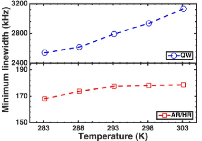
with a commercial 1.55lm QW DFB laser is performed, with the temperature being varied from 283 K to 303 K. Figure5
unveils that the minimum linewidth of the QD laser is rather insensitive to temperature with only an increase of 5% at 303 K above the minimum value of 170 kHz at 283 K. In con-trast, the QW DFB laser is increased by 23% (600 kHz) from 2.5 MHz at 283 K to 3.1 MHz at 303 K. Such a great thermal stability of QD lasers is attributed to the ultimate carrier con-finement and to the quality of the QD materials, providing maximum gain. To better understand the temperature behavior, an excitonic rate equation model was developed, where the spontaneous emission noise and the carrier noise are taken into account through the Langevin approach in Ref.33, Fig.6 illus-trates the calculated spectral linewidth as a function of the drive current. Considering the same temperature range, numer-ical simulation shows a very good agreement with the experi-ment, while the figure in the inset confirms that the minimum linewidth is rather insensitive to the operating temperature. The simulation agrees well with the experimental tendency; however, neither the slope difference nor the rebroadening is reproduced because the model does not include the flicker noise and the LSHB.
Owing to the low inversion factor, these results show the potential of QDs as a gain medium for narrow spectral linewidth lasers. Using a DFB laser with a lowjL and asym-metric facet coatings, a spectral linewidth of 160 kHz
(80 kHz intrinsic) is demonstrated. The temperature insensi-tive behavior between 283 K and 303 K agrees well with sim-ulation. Symmetric anti-reflection facet coatings are also used to reduce the LSHB and make the spectral linewidth rather independent of the drive current. These results show the importance of controlling spatial nonlinearities for narrow linewidth operation at high powers which is of paramount importance not only for coherent communication systems but also for high resolution spectroscopy, high purity photonic microwave generation, and on-chip atomic clocks.
This work was funded by the European Office of Aerospace Research and Development (EOARD) under Grant No. FA9550-15-1-0104.
1K. Kikuchi,IEEE J. Lightwave Technol.
34, 157 (2016).
2T. Kita, R. Tang, and H. Yamada,IEEE J. Sel. Top. Quantum Electron. 22, 1500612 (2016).
3P. S. Zori,
Quantum Well Lasers (Academic Press, 1993). 4
S. Takano, T. Sasaki, H. Yamada, M. Kitamura, and I. Mito, Electron. Lett.25, 356 (1989).
5
E. Kapon, Semiconductor Lasers I: Fundamentals (Academic Press, 1999).
6M. R. Matthews, K. H. Cameron, R. Wyatt, and W. J. Devlin,Electron.
Lett.21, 113 (1985).
7Z. Zhike, L. Jianguo, L. Yu, G. Jinjin, Y. Haiqing, B. Jinhua, and Z. Ninghua, in Asia Communications and Photonics Conference, paper AM1B.3, 2015.
8M. Okai, M. Suzuki, T. Taniwatari, and N. Chinone,Jpn. J. Appl. Phys.,
Part 133, 2563 (1994).
9B. Kelly, R. Phelan, D. Jones, C. Herbert, J. O’Carroll, M. Rensing, J. Wendelboe, C. B. Watts, A. Kaszubowska-Anandarajah, P. Perry, C. Guignard, L. P. Barry, and J. O’Gorman, Electron. Lett. 43, 1282 (2007).
10N. Pourshab, A. Gholami, M. J. Hekmat, and N. Shahriyari,J. Opt. Soc.
Am. B34, 2414 (2017).
11C. T. Santis, S. T. Steger, Y. Vilenchik, A. Vasilyev, and A. Yariv,Proc.
Natl. Acad. Sci.111, 2879 (2014).
12M. T. Crowley, N. A. Naderi, H. Su, F. Grillot, and L. F. Lester, “GaAs based quantum dot lasers,” in Advances in Semiconductor Lasers, Semiconductors and Semimetals, edited by J. J. Coleman and A. C. Bryce (Academic, 2012), vol. 86, pp. 371–417.
13
G. Eisenstein and D. Bimberg, Green Photonics and Electronics (Springer, 2017).
14
F. Lelarge, B. Dagens, J. Renaudier, R. Brenot, A. Accard, F. van Dijk, D. Make, O. Le Gouezigou, J.-G. Provost, F. Poingt, J. Landreau, O. Drisse, E. Derouin, B. Rousseau, F. Pommereau, and G.-H. Duan,IEEE J. Sel. Top. Quantum Electron.13, 111 (2007).
15
P. Poole, K. Kaminska, P. Barrios, Z. Lu, and J. Liu,J. Cryst. Growth311, 1482 (2009).
16
H. Su and L. F. Lester,J. Phys. D: Appl. Phys.38, 2112 (2005).
17Z. Lu, P. Poole, J. Liu, P. Barrios, Z. Jiao, G. Pakulski, D. Poitras, D. Goodchild, B. Rioux, and A. Springthorpe, Electron. Lett. 47, 818 (2011).
18
A. Becker, V. Sichkovskyi, M. Bjelica, A. Rippien, F. Schnabel, M. Kaiser, O. Eyal, B. Witzigmann, G. Eisenstein, and J. Reithmaier,Appl. Phys. Lett.110, 181103 (2017).
19A. Yariv,
Quantum Electronics (Wiley, 1989). 20
C. Wang, K. Schires, M. Osinski, P. J. Poole, and F. Grillot,Sci. Rep.6, 27825 (2016).
21
S. Osborne, P. Blood, P. Smowton, J. Lutti, Y. Xin, A. Stintz, D. Huffaker, and L. F. Lester,IEEE J. Quantum Electron.40, 1639 (2004).
22
J. E. Haysom, G. C. Aers, S. Raymond, and P. J. Poole,J. Appl. Phys.88, 3090 (2000).
23J. E. Carroll, J. Whiteaway, and D. Plumb,
Distributed Feedback Semiconductor Lasers (IEEE, 1998).
24H. Huang, K. Schires, P. J. Poole, and F. Grillot,Appl. Phys. Lett. 106, 143501 (2015).
25T. Okoshi, K. Kikuchi, and A. Nakayama, Electron. Lett. 16, 630 (1980).
FIG. 5. Minimum linewidth as a function of temperature for a commercial QW DFB laser (blue) and an AR/HR QD DFB laser (red).
FIG. 6. Calculated spectral linewidth as a function of the drive current for the AR/HR QD DFB laser. The inset shows the temperature dependence of the minimum linewidth at 155 mA.
26
P. Thompson, D. E. Cox, and J. B. Hastings,J. Appl. Crystallogr.20, 79 (1987).
27F. Girardin, G.-H. Duan, and P. Gallion,IEEE Photonics Technol. Lett. 8, 334 (1996).
28C. Redlich, B. Lingnau, H. Huang, R. Raghunathan, K. Schires, P. Poole, F. Grillot, and K. L€udge, IEEE J. Sel. Top. Quantum Electron.23, 1 (2017).
29
M.-C. Wu, Y.-H. Lo, and S. Wang,Appl. Phys. Lett.52, 1119 (1988).
30
H. Virtanen, T. Uusitalo, and M. Dumitrescu,Opt. Quantum Electron.49, 160 (2017).
31K. Kechaou, B. Thedrez, F. Grillot, G. Aubin, C. Kazmierski, and D. Erasme, in 25th IEEE International Photonics Conference paper TuN5 (2012), pp. 332–333.
32F. Grillot,J. Quantum Electron.
45, 720 (2009).
33C. Wang, J. P. Zhuang, F. Grillot, and S. C. Chan,Opt. Express
24, 29872 (2016).