HAL Id: hal-01208288
https://hal.archives-ouvertes.fr/hal-01208288
Submitted on 2 Oct 2015
HAL is a multi-disciplinary open access
archive for the deposit and dissemination of
sci-entific research documents, whether they are
pub-lished or not. The documents may come from
teaching and research institutions in France or
abroad, or from public or private research centers.
L’archive ouverte pluridisciplinaire HAL, est
destinée au dépôt et à la diffusion de documents
scientifiques de niveau recherche, publiés ou non,
émanant des établissements d’enseignement et de
recherche français ou étrangers, des laboratoires
publics ou privés.
Sagnac Loop Incorporating a Semiconductor Optical
Amplifier Without Bias Current to Receive/Modulate
Weak RF Signals
Ricardo M. Ribeiro, Vinicius N.H. Silva, Andrés P.L. Barbero, Frédéric
Lucarz, Bruno Fracasso
To cite this version:
Ricardo M. Ribeiro, Vinicius N.H. Silva, Andrés P.L. Barbero, Frédéric Lucarz, Bruno
Fra-casso. Sagnac Loop Incorporating a Semiconductor Optical Amplifier Without Bias Current to
Re-ceive/Modulate Weak RF Signals. ICTON 2014 : 16th International Conference on Transparent
Optical Networks, Jul 2014, Graz, Austria. �10.1109/ICTON.2014.6876705�. �hal-01208288�
Sagnac Loop Incorporating a Semiconductor Optical Amplifier
Without Bias Current to Receive/Modulate Weak RF Signals
Ricardo M. Ribeiro, Vinicius N.H. Silva, Andrés P.L. Barbero, Frédéric Lucarz* and Bruno Fracasso*
Dept. Engenharia de Telecomunicações,Universidade Federal Fluminense, 24.210-240, Niterói, Brasil * Optics Department,Telecom Bretagne, 29280, Brest, France
Tel: (5521) 2629 5602, Fax: (5521) 2629 5515, e-mail: [email protected]
ABSTRACT
This paper describes the conception, design and numerical simulations of an electromagnetic-receiver & optical-modulator based on a solely semiconductor optical amplifier (SOA) and a fibre-optic Sagnac loop incorporating a SOA both without bias current. Only the interferometric device was able to detect weak high-frequency RF carriers from hundred pW to hundreds nW power delivering an output with 37% optical offset in the 0.3-10.0 GHz frequency range. Even though the adopted SOA model presents around 1 ns gain recovery time, RF carriers up to 30 GHz frequency were received/modulated because a full gain recovery was not needed.
Keywords: optical signal processing, optical receiver, microwave-photonics, semiconductor optical amplifier, modulator, electromagnetic probe.
1. INTRODUCTION
The use of passive or active (with an electronic amplifier) antennas to receive RF signals is well known where the signals are always kept in the electrical domain. In Radio-over-Fibre (RoF) applications [1], the captured RF signals should be transmitted using lightwave carrier along an optical fibre. There are many techniques to build a RoF transceiver.
An RF signal after captured by an antenna may directly (analogically) modulates an optical carrier by means of direct modulation on Light-Emitting Diode (LED) and Laser Diode (LD) or external modulation on Mach-Zehnder Electro-Optic Modulator (MZ-EOM) or Electro-Absorption Modulator (EAM) [2]. In all instances, the amplitude of generated optical signal depends on the amplitude of launched electrical signal and the output is intrinsically non-amplified. However, in many situations the RF signal should be electronically amplified before optical modulation. Despite the use of internal or external modulation, the modulated optical signal is always accompanied by an optical offset [2].
In direct modulation, the amplitude of output signals depends on the gain modulation (mW/mA) of the optical source. In external modulation, the amplitude of output signals depends on the slope of device transfer curve and the Continuous Wave (CW) optical power launched in such modulator device [2].
Once the modulator is already selected, the output modulation depth will depend on the amplitude of the RF signal. For very weak RF signals a low-noise pre-amplifier is highly desirable. A device using a microwave/optical resonator was already reported [3].
Since 2006 we have being developing electromagnetic probes based on optoelectronic technology. Early efforts were focused on the LED + plastic optical fibres (POF) based links [4,5] mainly due to convenience and limited resources in our laboratory. In [4], the main contribution was the demonstration of a technique able to allow a free-error analogue remote measurement of electromagnetic field amplitude even when an attenuation variation occur in either point of a fibre-optic link. In [5], is described the impedance matching between an antenna and LED (optoelectronic device) where the concept of “effective capacitance” was introduced to simultaneously taking into account the LED impedance and the parasitic originated from the device package. Such papers were constrained on investigations of optical links based on highly multimode Poly-Methyl-Methacrylate (PMMA)-based optical fibres in the visible spectra limited up to ~500m length or by the ~ 5 MHz.km product. Of course the LED + PMMA-POF based links are not suitable to transmit broadband RF signals for long distances.
This paper proposes, designs and numerically simulates the operation in the time-domain of two devices able to detect weak RF (~ nW) signals: a solely SOA based on gain modulation and a Sagnac interferometer incorporating a SOA in the loop based on gain + phase modulation. Both devices without bias current are intended to be a fast receiver/modulator (up to 30 GHz) of low amplitude ≤ 1 mA or ~ nW power RF signals, even regarding a SOA presenting ~ 1 ns recovery time. Therefore, this paper describes a non-conventional use of SOAs by using IRF as the input launched in their electrical port. The devices are able to generate 1550 nm wavelength modulated carrier coupled to single-mode silica optical fibres potentially useful to convert and process microwave signals in the optical domain [3]. Although the input impedance of SOAs including it package parasitic is a very important issue, it is here assumed that an effective RF current up to 30 GHz and ≤ 1 mA is generated when an RF voltage flows through a low resistive impedance (~ 7 Ω) characteristic of SOAs
2
electronic RF amplifier is used here. Usually, the use of an electronic amplifier is needed, but due the added noise and nonlinear distortions the resulting analogue link presents a reduced Third-Order Intercept Point (IP3) [7].
2. THE OPTICAL CIRCUITS
Two optical circuits were designed and numerically simulated in this paper: Circuit #1 using a solely SOA (gain modulation) in a non-interferometric configuration and a Circuit #2 using a SOA incorporated in a Sagnac interferometric ring (gain and phase modulation). Comparisons between the performances of both circuits are outlined. Figures 1 and 2 schematically show the circuit diagrams #1 and #2, respectively. In both schemes, an RF generator replaces the antenna.
! RF generator DC bias source Bias-T 1550 nm 20 mW CW laser bulk 500 µm SOA OPTICAL INPUT OPTICAL OUTPUT
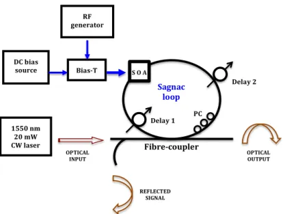
Figure 1. The optical circuit diagram #1 of an RF receiver/modulator for low-amplitude signals using a solely SOA. ! ! ! ! ! ! ! ! ! ! ! Fibre&coupler, , Sagnac, loop, S,O,A, , ,, , Delay,2,, PC, , Delay,1,, RF, generator, , DC,bias, source, , Bias&T,! 1550,nm, 20,mW, CW,laser, , , OPTICAL, INPUT, , OPTICAL, OUTPUT, , REFLECTED, SIGNAL,
Figure 2. The optical circuit diagram #2 of an interferometric RF receiver/modulator for low-amplitude signals using a Sagnac incorporating an SOA in the loop.
The optimisation of the Circuit #2 was carried out by setting f = 20 GHz operation frequency and the following parameters were achieved: phase-angle = 2.0o equivalent to the PC adjustment, I
bias = 0 mA meaning that none DC current bias was applied to the SOA and none band-pass filter was used because ASE noise is not generated, amplitude (Ain) of the RF source = ± 1 mA, delays in the Sagnac loop = 38 ps/62 ps, LSOA = 500 µm, PIN = 20 mW as the input continuous wave (unmodulated) optical power of 1550 nm wavelength. For comparison purposes, the adjusted parameters are the same for the both Circuits #1 and #2. However, despite the operation frequency, none response was achieved for the Circuit #1, but only for the Circuit #2.
3. LINEARITY RESPONSE OF CIRCUIT #2
In order to characterise the linearity response of Circuit #2, numerical simulations were carried out by sweeping the input sinusoidal current amplitude Ain at f = 5 GHz as is shown in the plot of Fig. 3. The calculated output signals were 5 GHz sinusoidal 1550 nm wavelength optical analogue of the IRF(t).
Figure 3 – Linearity response of Sagnac + SOA RF receiver/modulator circuit at 5 GHz.
For RF amplitude ≥ 4 mA output optical pulses were calculated. From Fig. 3, a high linearity is observed with ≈ 55 nW/mA gain modulation. A dynamic range for the RF current detection of 20log(2/0.01) = 46 dB is achieved equivalent to 23 dB incident power.
4. FREQUENCY RESPONSE OF THE CIRCUIT #2
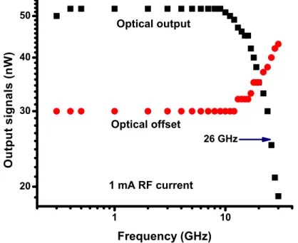
Numerical simulations were carried out in order to characterise the frequency response of Circuit #2 by using sinusoidal signal input. The amplitude was set at 1 mA and the frequency f was swept from 0.3 GHz to 30 GHz. Figure 4 shows the plots from the calculations. The output signals were sinusoidal 1550 nm wavelength optical analogue of the IRF(t).
4
From Fig. 4, a flat response was calculated up to 10 GHz whereas the 3 dB cut-off frequency was achieved to be around 26 GHz. The optical offset response of Circuit #2 was also calculated and plotted in Fig. 4 as to be ≈ 37% from 0.3 to 10.0 GHz. Both frequency response (optical output) and the optical offset are a “mirror reflection” of each other. It can be observed that from the start of the frequency response roll-off curve the optical offset starts to increase. This is expected since due the limited recovery time of the SOA, the modulation depth of output signal is reduced as the input frequency increases.
5. CONCLUSION
In this paper, it was numerically shown that only the Sagnac interferometric device incorporating a SOA without current bias (none ASE) in the loop was able to detect very small input signals, i.e. RF current amplitude as low as 10 µA equivalent to sub-nW incident power. The output signals present reasonable optical offset that can be suppressed by electronic means. It has shown a highly linearity with 55 nW/mA gain modulation for 5 GHz and 23 dB dynamic range for RF power detection. The frequency response was calculated to be flat up to 10 GHz and exhibits frequency cut-off of 26 GHz despite the SOA recovery time of ≈ 1 ns. This was feasible due to the partial recovery gain typical of resonant optical nonlinearity of SOAs. Even though it is not explored in this paper, the device here described may be implemented to simultaneously carry out the optical sampling [8].
Present device is in a sense similar to a laser diode operating below the threshold or even without bias current whereupon it is expected a very low gain modulation. Operating an LD or MZ-EOM in the linear region as a detector of pW-nW RF power, a modulated optical power is achieved but buried in a very large optical offset.
Anyway, it should be observed that the present device generates an optical signal that can be further optically post-amplified using an EDFA or SOA.
ACKNOWLEDGEMENTS
Ricardo M. Ribeiro thanks the team at Département d’Optique of Telecom Bretagne and the CapilRTM platform for hosting his Post-Doctoral study during which the present work was carried out. The authors also thank INCT-Fotonicom/CNPq and Fundação Capes under grant BEX 9096-11-6.
REFERENCES
[1] R.C. Williamson and R.D. Esman: RF Photonics, J. of Lightwave Technol., vol. 26, no. 9, pp. 1145-1151, 2008.
[2] C.H. Cox III: Analog Optical Links: Theory and Practice, Cambridge University Press, 2004.
[3] V.S. Ilchenko, et al: Sub-MicroWatt Photonic Microwave Receiver, Photon. Technology Lett., vol. 14, no. 11, pp. 1602-1604, 2002.
[4] R.M. Ribeiro, et al: An optoelectronic probe with loss compensation for electromagnetic monitoring at low frequencies, Meas. Science and Technol., vol. 20, 115111, 2009.
[5] R.M. Ribeiro, et al: Optimisation of a device for pick-up of low-frequency radio signals and transmission over polymer optical fibres, Annals of Telecommunications, vol. 68, no. 1-2, pp. 81-93, 2013.
[6] A.L. Toazza, et al: Experimental and Theoretical Analysis of Packaging Inductances and Stray
Capacitances of a Semiconductor Optical Amplifier, 2006 International Telecommunication Symposium
(ITS 2006), Fortaleza, CE, Brasil, September 3-6, pp. 63-66, 2006.
[7] C.H. Cox III, et al: Limits on the performance of RF-over-fiber links and their impact on device design,
Trans. on Microwave Theory and Techn., vol. 54, no. 2, pp. 906-920, 2006.
[8] R.M. Ribeiro, F. Lucarz and B. Fracasso: An All-Optical Sampler for Digitising Radio-over-Fibre Transceivers, 8th IEEE Conference on Network and Optical Communications (NOC2013), July 10-12, Graz, Austria, pp. 27-34, 2013.