HAL Id: hal-01809330
https://hal.archives-ouvertes.fr/hal-01809330
Submitted on 6 Jun 2018
HAL is a multi-disciplinary open access
archive for the deposit and dissemination of
sci-entific research documents, whether they are
pub-lished or not. The documents may come from
teaching and research institutions in France or
abroad, or from public or private research centers.
L’archive ouverte pluridisciplinaire HAL, est
destinée au dépôt et à la diffusion de documents
scientifiques de niveau recherche, publiés ou non,
émanant des établissements d’enseignement et de
recherche français ou étrangers, des laboratoires
publics ou privés.
Effect of BJT’s parasitics on computing cells for analog
decoders
Nicolas Duchaux, Cyril Lahuec, Fabrice Seguin, Matthieu Arzel, Michel
Jezequel
To cite this version:
Nicolas Duchaux, Cyril Lahuec, Fabrice Seguin, Matthieu Arzel, Michel Jezequel. Effect of BJT’s
parasitics on computing cells for analog decoders. NEWCAS-TAISA, 22-25 juin 2008, Montréal,
Québec, Canada, Jun 2008, Montréal, Canada. �hal-01809330�
Effect of BJT’s parasitics on
computing cells for analog decoders
Nicolas Duchaux, Cyril Lahuec, Fabrice Seguin, Matthieu Arzel, Michel Jézéquel
Département Electronique TELECOM BRETAGNE Brest, Brittany, France [email protected]
Abstract—This paper analyses the effect of inherent bipolar transistor parasitic elements over the computing nodes performance used in BJT analog decoders. It is shown that these undesirable effects significantly degrade, up to 85%, the conversion of Log-Likelihood Ratios into probabilities. This can lead to a wrong decoding outcome when complex computing nodes are designed. Simulation results are shown for a 0.25-µm BiCMOS process from NXP.
I. INTRODUCTION
Several works have been published over the last 15 years on analog decoding. Most of them are dealing with Turbo and LDPC codes [1-5] and few with exotic codes such as Cortex codes [6]. All these codes however can be decoded using two mathematical operators which are the addition and the multiplication. The operands are probabilities which are simply extracted from an additive white gaussian noise (AWGN) channel using the exponential I-V characteristic of a forward-biased BJT or a subthreshold-biased MOS transistor. The latter is preferred for power issues and the former for speed issues. Hence, it exists two ways of implementing the computing nodes. The majority of the papers published on the design of analog decoders refers to MOS designs such as [2-4] and few deal with BJT designs [1][5].
When comparing simulated and actual decoding performance in terms of Bit-Error Rate (BER) most works show discrepancies [2-5] between the two, except in [1] for which there is a good agreement. The performance degradation ranges from few hundredths of dBs [2][3][5] up to few dBs [4]. The reason for this is that the behavioral models used describe the decoding algorithm, not the functioning of the decoders. However, very few of these papers attempt to explain the origin of the discrepancies. [2] showed, using behavioral modeling, that the origin of the loss was due to mismatches in MOS current mirrors. An interesting point is that the BJT decoder designed in [1] performs as well as its model while the more complex decoder designed in [5] is 0.3dB away from its ideal performance. This suggests a link between complexity and performance degradation. The decoder in [1] decodes a
simple binary code and uses simple Gilbert multipliers while in [5] the double-binary code to decode requires m-ary multipliers [7] (having more than two differential inputs).
Hence, this paper addresses the effect of parasitic emitter resistors over the computing cell used in BJT-based analog decoders. The paper presents results for multipliers used to decode simple binary and double-binary codes. It is shown that while for the former the parasitic elements modify the probabilities they do not change their ranking order. For the latter, they can actually invert that ranking therefore potentially introducing additional decoding errors.
The paper is organized as follows. Section II presents the basic multiplier cell. Section III deals with the effect of the BJT’s parasitic emitter resistor over the LLR-to-probability conversion and how it affects simple Gilbert multipliers. The result is extended to m-ary multipliers with a case study in section IV. Section V concludes the paper.
II. BASIC COMPUTING CELL
A. Converting LLRs into probabilities
A convolutional circular binary code can be decoded with the Maximum A Posteriori (MAP) algorithm [8]. It uses only two mathematical operators (addition and multiplication) and two functions (logarithm and exponential). The last two are necessary for converting log-likelihood ratios (LLR) to probabilities and vice-versa. If X is a binary random variable and x its outcome, the LLR of X, L(X), is defined as:
(
)
(
)
=
=
=
ln
0
1
)
(
x
P
x
P
X
L
X X (1)The exponential and the natural logarithm functions are readily available from a forward active region BJT. Using the well known Ebers-Moll model, the collector current IC depends on the base-emitter voltage VBE:
T BE V V S C
I
e
I
≈
(2)where IS is the saturation current and VT is the thermal
voltage. When diode connected, the BJT produces a voltage
V which depends on the current I flowing through it:
=
S TI
I
V
V
ln
(3)Associating a current with a probability and a voltage with an LLR, it is thus possible by using transistors and diodes to convert LLRs to probabilities, equation (2), and probabilities to LLRs, equation (3), respectively. This is a clear advantage of analog decoders over digital decoders since currents, representing the probabilities, can be easily added and multiplied. Thus, the MAP algorithm can be implemented using a BJT-based analog network [1].
B. Multiplying and adding probabilities
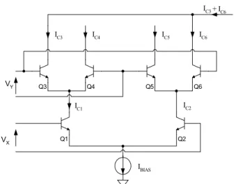
The Gilbert multiplier shown in Fig 1 is use to perform both the LLR-to-probability conversion and the probability multiplication. If one considers that both input voltages are proportional to LLRs, then the collector currents IC1 and IC2
are proportional to PX(x=1) and PX(x=0) respectively. The
proportionality constant is the bias current IBIAS. Since the
upper pairs are biased with a current proportional to a probability, IC1 and IC2, then the collector currents of Q3-Q6
are each proportional to a product of probabilities:
(
) (
)
(
) (
)
(
) (
)
(
) (
Y)
BIAS X C BIAS Y X C BIAS Y X C BIAS Y X CI
y
P
x
P
I
I
y
P
x
P
I
I
y
P
x
P
I
I
y
P
x
P
I
1
0
0
0
0
1
1
1
6 5 4 3=
=
=
=
=
=
=
=
=
=
=
=
(4)Adding product of probabilities is then simply a matter of connecting wires together as shown in Fig.1.
III. BJT’S NON-IDELATIES
A. Parasitic emitter resistor
The Gilbert multiplier functioning described above assumes ideal BJTs, i.e. it supposes that they are fully described by the Ebers-Moll model defined by equation (2). However, a parasitic element, which is usually underestimated, may significantly alter the conversion of LLRs into probabilities. When the parasitic emitter resistor RE is taken into account the collector current is more
accurately defined as:
T C E T BE V I R V V S C
I
e
e
I
−≈
(5)The value of RE is inversely proportional to the area of the
emitter. One may consider that designing with large BJTs will make RE negligible. Unfortunately, to compete with the
Q3 Q4 Q5 Q6 Q1 Q2 VY VX IC4 IC1 IC3 IC5 IC6 IBIAS IC2 IC3+ IC6
Figure 1: BJT Gilbert multiplier, two input voltages and four output currents. 0 20 40 60 80 100 0 20 40 60 80 100 Ideal case Uncorrected Parasitic RE compensated Out put p ro bab ili ty r a tio
Input probability ratio
Figure 2: Probability ratio transfer function of a minimal size emitter-coupled bipolar pair Q1-Q2 compared with ideal probability ratio transfer function and with corrected-RE probability transfer function.
NXP’s QUBIC4 0.25-µm BiCMOS process, smallest BJT and IBIAS
=250µA.
ever-shrinking digital decoders, it is preferable to design with the smallest BJT available in the process. For instance, in NXP’s QUBIC4 0.25-µm BiCMOS process, the parasitic RE is around 220Ω for the smallest available BJT.
The problem becomes even more acute when the biasing current is a few hundreds of µA. This is chosen to correctly bias the cell and to increase the decoding speed. Fig. 2 represents the output probability ratio, i.e. the ratio of the two simulated collector currents IC1and IC2, versus the input
probability ratio, i.e. exp(VX/VT). Ideally, the obtained curve
should be a straight line with a slope of 1. As one can see the result is far from the ideal case and the conversion error is as high as 85% for an input LLR of 100. Hence the usual assumption of having an ideal exponential relationship between the collector current and the base-emitter voltage is absolutely incorrect. It is interesting to see the actual contribution of RE to this error. This can be done by adding
-0.2 -0.1 0.0 0.1 0.2 0.0 0.1 0.2 0.3 0.4 0.5 Error Out p ut pr obab ilit y IC6 /IBI A S , V Y =0 VX IC6 actual IC6 ideal case
Figure 3: Degradation of output probability of the Gilbert multiplier due to parasitic effects (transistor level simulation). The curve is plotted versus the lower differential-pair input voltage VX when VY=0. NXP’s QUBIC4
0.25-µm BiCMOS process, smallest BJT and IBIAS=250µA.
an ideal resistor REC such as REC = -RE at each transistor
emitter in the Gilbert cell. Hence, each parasitic RE is fully
compensated and the output probability ratio should get closer to the ideal one. As seen from Fig. 2, RE is the main
source of conversion error as it would be reduced down to 20% by compensating the parasitic resistors. The simulation also shows that other effects impair the conversion but that they are less important.
B. Probability ranking
A question arises from the above discussion, is this really a problem for the decoder? It is known that in digital decoders, the value of the probability is voluntarily truncated to speed up the turbo-decoding process without degrading the overall performance. The degradation observed in Fig. 3 can be interpreted as such. The output probability IC6/IBIAS is plotted
versus the lower input voltage VX (VY = 0, IBIAS = 250µA).
The probability is reduced for positive values of VX
(probability of having a “1”) and increased for negative ones (probability of having a “0”). The degradation is more important around zero; that is to say for cases harder to solve for the decoder. Simulations show, however, that the ranking of the four output probabilities, equation (4), is not modified compared to the ideal case. It simply means that on a single stage, no error is introduced. This most likely explains in [1] the performance matching between of the ideal behavioral model and of the actual decoder.
IV. M-ARY CASE
A. Extended multiplier
The above section described the implications when dealing with simple multipliers. How does this problem affect m-ary computing cells? M-ary computing cells are described in [9].
Figure 4: Extended Gilbert cell for m-ary code, nx + ny inputs, nx x ny
currents.
The Gilbert cell shown in Fig. 1 can be extended to a larger field of probability multipliers as illustrated in Fig. 4. The lower stage is an emitter-coupled set of bipolar transistors whose bases are connected to nX voltages VX which are
proportional to the log-likelihood ratio of the data x. The upper stage is made up of nX identical emitter-coupled
bipolar sets, each of them being connected to a different collector on the lower level. Thus, the outputs are nX × nY
currents Ioutkgiven by:
( )
( )
[
[ ]
]
∈
−
∈
=
+ × y x BIAS j Y i X out j n ij
n
n
i
I
y
P
x
P
I
y1
,
1
,
0
(6) Unlike in the binary case previously studied, it may happen that not all the output currents are necessary to implement the decoding algorithm. This type of cases happens in fact quite often when designing double-binary decoders. For instance, this happens in the module computing the four probabilities (one per double-binary symbol) on which the hard decision is taken [5]. For the sake of simplicity, the double-binary symbols d are noted as follows: “00” →0, “01” →1, “10” →2 and “11”→3. A multiplier having eight inputs, PX(xi) andPY(yi) for i ∈ [0, 3], and requiring only four outputs, Pr(d=i)
for i ∈ [0, 3], out of the sixteen available is simulated. The fact that not all the output currents are used implies renormalization. So the symbol probability is given by:
(
)
( ) ( )
∑
( ) ( )
==
=
3 0Pr
i X i Y i i Y i Xx
P
y
P
x
P
y
P
i
d
(7)A case, shown in Fig. 5, is taken as an example to better explain what can happen. Fixing some to an input probability of 0 reduces the number of inputs:
MULT fixed at 0% fixed at 0% fixed at 0% fixed at 0% fixed at 0% fixed at 0% fixed at 45% fixed at 55% Pr(d=3) Pr(d=2) Pr(d=1) Pr(d=0) ) (i Xx P 0 0 ) (i Yy P Figure 5: 4:4:4 multiplier. 0.0 0.2 0.4 0.6 0.8 1.0 0.38 0.40 0.42 0.44 0.46 0.48 0.50 0.52 0.54 0.56 0.58 0.60 0.62 0.64 0.66 Probability inversion O u tp ut pr ob ab ili ty Input probability PX(x1) Pr*(d=1), simulated Pr(d=1), ideal case Pr* (d=0), simulated Pr(d=0), ideal case
Figure 6: Inversion in the ranking of output probability in a 4:4:4 multiplier. PX(xi) and PY(yi) equal 0 when i = 3 or 4. NXP’s QUBIC4
0.25-µm BiCMOS process.
( )
( )
2
0
0
≥
∀
=
=
i
y
P
x
P
i Y i X (8) hence:( )
( )
( )
1( )
0 0 11
1
y
P
y
P
x
P
x
P
Y Y X X−
=
−
=
(9) Rearranging equations (7), (8) and (9) yields:( )
( )
(
)
( )
(
1)
(
)
( )
1 1 1 ) 1 Pr( 1 1 ) 1 Pr( 1 ) 1 Pr( x P d x P d x P d y P X X X Y = − + − = − = = (10) B. Probability rankingFrom equation (10), fixing the symbol probability makes
PY(y1) only a function of PX(x1). For instance, by fixing
Pr(d=1) to 55% and varying PX(x1), one can plot the
simulated output probabilities Pr*(d=1) and Pr*(d=0) taking
equation (5) into account. If the multiplier were ideal, then
Pr*(d=1) and Pr*(d=0) would remain at 55% and 45%,
respectively. However, as shown in Fig. 6, it is not the case and even worse, the outcome can be inverted. The most likely symbol can become “00” (d=1) instead of “01” (d=0). Hence, unlike in the binary case, the multiplier may well introduce additional errors, thus degrading the decoder’s performance in terms of BER.
V. CONCLUSION
This paper showed how the bipolar transistor’s parasitic elements introduce a significant degradation when converting data from the channel, LLRs, into probabilities. It is shown that the most degrading element is the parasitic emitter resistor. This work shows that this is more a problem when decoding m-ary codes than binary codes. Indeed, for double-binary codes, there is a possibility to invert the probability ranking. As the decoding algorithm to output the decoded bits uses probabilities, errors can be introduced. This suggests that complex decoders require additional circuits to counteract the effect of parasitic elements.
REFERENCES
[1] M. Moerz, T. Gabara, R. Yan, and J. Hagenauer, “An analog 0.25-µm BiCMOS tailbiting MAP decoder", in Proc. of IEEE International Solid-State Circuits Conference, Feb. 2000, pp. 356-357.
[2] D. Vogrig, A. Gerosa, A. Neviani, A. Graell i Amat, G. Montorsi, S. Benedetto, “A 0.35-µm CMOS analog turbo decoder for the 40-bit rate 1/3 UMTS channel code”, in IEEE J. of Solid-State Circuits, vol. 40, n° 3, pp. 753-762.
[3] V.C Gaudet, P.G. Gulak, “A 13.3-Mb/s 0.35µm CMOS analog turbo decoder IC with a configurable interleaver” in IEEE J. of Solid-State Circuits, vol. 38, Issue 11, Nov. 2003, pp. 2010 – 2015.
[4] F. Gioulekas, M. Birbas, A. Birbas, G. Bilionis, K. Efstathiou, M. Papamichail, “A high-speed SiGe BiCMOS analog MAP decoder”, in Proc. 5th Analog Decoding Workshop, Torino, Italy, June 5-6, 2006,
pp. 19-22.
[5] C. Lahuec, G. Le Mestre, F. Seguin, M. Arzel and M. Jézéquel, “Design and test of a 0.25µm-BiCMOS double-binary analogue APP Decoder”, 5th Analogue Decoding Workshop, pp. 35-38, Torino, Italy,
June 5-6 2006.
[6] J. P. Chamorro, C. Lahuec, F. Seguin, and M. Jézéquel, “Cortex codes and analogue decoding”, 6th Analogue Decoding Workshop, Montréal,
Québec, Canada, May 24-25 2007.
[7] M. Arzel, C. Lahuec, M. Jézéquel and F. Seguin, “Analogue decoding of duo-binary codes”, in Proc. International Symposium on Information Theory and its Applications 2004, Parma, Italy, pp. 332-335, October 10-13, 2004.
[8] J. B. Anderson and S. M. Hladik, “Tailbiting MAP decoders”, IEEE Journal on Selected Areas in Communications, vol. 16, no. 2, Feb. 1998, pp. 297-302.
[9] M. Arzel, C. Lahuec, M. Jézéquel, F. Seguin, “Analogue decoding of duo binary codes”, 2004 International Symposium on Information Theory and its Applications, Parma, Italy, October 10-14 2004