HAL Id: hal-02975947
https://hal.insa-toulouse.fr/hal-02975947
Submitted on 23 Oct 2020HAL is a multi-disciplinary open access archive for the deposit and dissemination of sci-entific research documents, whether they are pub-lished or not. The documents may come from teaching and research institutions in France or abroad, or from public or private research centers.
L’archive ouverte pluridisciplinaire HAL, est destinée au dépôt et à la diffusion de documents scientifiques de niveau recherche, publiés ou non, émanant des établissements d’enseignement et de recherche français ou étrangers, des laboratoires publics ou privés.
Crashworthiness of poplar wood veneer tubes
R. Guélou, Florent Eyma, Arthur Cantarel, Samuel Rivallant, Bruno Castanié
To cite this version:
R. Guélou, Florent Eyma, Arthur Cantarel, Samuel Rivallant, Bruno Castanié. Crashworthiness of poplar wood veneer tubes. International Journal of Impact Engineering, Elsevier, 2021, 147, pp.103738. �10.1016/j.ijimpeng.2020.103738�. �hal-02975947�
1
Crashworthiness of poplar wood veneer tubes
12
R. Guéloua, F. Eymaa, A. Cantarela, S. Rivallanta, B. Castaniéa,* 3
aInstitut Clément Ader (ICA), ISAE, CNRS UMR 5312-INSA-Mines Albi-UPS, Toulouse, France 4
* Corresponding author: bruno.castanie@insa-toulouse.fr 5
6
Keywords: Wood, Poplar, Crushing, Energy absorption, Static, Dynamic 7
8
Abstract 9
This work studies the potential of using wooden tubes for crash applications. The tubes were made from 10
1 mm thick “I214” poplar veneers, according to different stacking sequences. Four configurations were 11
characterized under static crushing (5 mm/min) and the one that performed best ([90/04/90]) was chosen
12
to undergo dynamic tests under a drop weight tower (5.7 m/s). This configuration presents significant 13
energy absorption performance in static (31.6 J / g) and in dynamic (28.5 J / g) crushing for a material 14
that is natural, ecological (low carbon footprint), recyclable, and low cost in comparison with other 15
materials such as composite materials. As with composites, the position, number, and orientation of the 16
plies directly affect the amount of energy absorbed. The use of poplar, one of the weakest woods in 17
mechanical terms, shows the possibilities of wood for this use. 18
19
1. Introduction 20
Wood, by its nature, is an ecological material that has a very low grey energy (energy required from the 21
creation of the raw material to the installation of the finished product) due, in particular, to its capacity to 22
store carbon [1, 2]. It is also a recyclable material that, once it reaches the end of its life, can be used for 23
the manufacture of particle boards or for energy recovery (heating). Additionally, it is, a material that is 24
much cheaper than others. Wood or plywood are generally used in construction and furniture but also 25
2
have applications in other fields, such as civil light aviation, boating, and the nuclear industry or, in the 26
past, the automobile industry [3- 6]. Plywood has good weight specific mechanical properties under 27
bending, tension, compression and shear [7]. 28
There are few studies on the impact or crash behaviour of wood. Johnson analysed the problem in 1986, 29
mainly from a historical point of view in the naval field [8]. Some studies have been carried out to study 30
the dynamic behaviour of wood via tests on Hopkinson bars [9-12] but few dynamic studies have been 31
carried out on drop weight apparatus. Adalian and Morlier [13], however, studied the behaviour, in the 32
longitudinal and tangential directions, of poplar in the form of massive rectangular specimens with this 33
kind of tests. The objective of their study was to obtain enough static and dynamic compression data to 34
be able to model wood as a shock absorber. The force-displacement curve showed that the dynamic 35
performance of poplar was slightly better than its static performance in the longitudinal or tangential 36
direction (Plateau force, Energy Absorbed (EA) or Specific Energy Absorbed (SEA)). There is now 37
renewed interest in these materials and the issue [15-18]. Some very interesting studies have also been 38
conducted on the dynamic behaviour of coconut woods [19-21]. 39
Susainathan et al. studied various configurations of sandwich plates with composite skins (aluminium, 40
carbon, glass, and flax) and a plywood core subjected to low speed / low energy impacts [16]. They 41
demonstrated that, as a core material, it was better to have a plywood that multiplies the interfaces (i.e. 42
the number of plies) to improve the transverse behaviour and thus the impact response. These authors 43
also investigated the numerical modelling of this type of impact in a preliminary manner, but this is a new 44
field requiring a very great amount of characterization work [17]. It can therefore be argued that 45
experimental studies on these types of materials should be done first. Then the same authors tested 46
sandwiches and plywood alone in compression and compression after impact [18]. The two plywoods, 47
alone or sandwiched with aluminium, flax or glass skins, showed a remarkable response in compression 48
after impact of the panels with, in particular, the presence of a plateau on the force-displacement curve 49
3
and a high residual resistance. Because of these good characteristics of plywood after impact and 50
compression, the question arises as to the use of these structures for crash applications. 51
Given the small number of studies for wood, it is wise to focus on composite materials, which will serve 52
as a reference for this study because their use has increased significantly in recent years despite their 53
complexity [22]. In the crash domain, the low density and high specific resistances of composite materials 54
make it possible to obtain very interesting energy absorption when they are appropriate to the failure 55
mode [23-34]. The energy absorption potential of a material is assessed using the SEA (Specific Energy 56
Absorption, which corresponds to the energy absorbed per unit of mass). The different configurations and 57
numerous parameters that vary among the studies available in the literature generate a wide range of 58
SEA for composite materials. Guillon [23] showed that, for carbon-epoxy plates, the SEA varied according 59
to the main mode of damage. A pure splaying mode generated a low SEA, between 4 and 7 J/g. The SEA 60
was from 33 to 50 J/g for a failure mode with predominant fragmentation, and from 10 to 15 J/g in the 61
case of a combination of these two modes (known as brittle fracture mode). For circular carbon-epoxy 62
tubes with an internal diameter of 50 mm oriented at ± 15°, Wang et al. [26] obtained a SEA of 94 J/g, 63
and a SEA of 73 J/g for an orientation of ± 45°. Hamada et al. [27], also on circular carbon tubes with an 64
internal diameter of 50 mm [± 45°], found a SEA of 53 J/g. When the carbon fibres were combined with 65
a PEEK resin, a significant improvement was observed, with a SEA of 180 J /g. Glass fibres have 66
interesting SEA, and Hu et al. [28] obtained 77 J/g on 50 mm diameter circular tubes oriented at ± 15°. 67
With glass fibre tubes 55 mm in internal diameter, Song [29] reached 50 to 60 J/g depending on the 68
trigger, with fibres oriented at [±45°] and in local buckling mode. Yan and Chouw [30] obtained an optimal 69
configuration reaching 42 J/g on circular tubes with an internal diameter of 36 mm, made of flax fibres 70
with [0/90] stacking. For tubes, the failure mode corresponding to the formation of symmetrical or 71
asymmetrical folds creating multi-lobes (accordion mode) is generated by local buckling and concerns 72
ductile materials such as aluminium or Kevlar fibres (Fig. 1 (a) and (b)). The additional folds leading to 73
the formation of the accordion mode are created by a succession of local buckling events. During this 74
4
failure mode, energy is absorbed by the plasticization of the folds. Farley and Jones called this mode 75
"folding mode" or "local buckling mode" [31]. 76
The “splaying crushing mode” (name given by Hull [32]) or “lamina bending mode” (name given by Farley 77
and Jones [31]) concerns fragile materials. Splaying corresponds to a division of the walls into two parts 78
(Fig 1 (c)). The splaying mode starts with an interlaminar crack or a delamination, which propagates and 79
separates the structure into two parts. The bending of these two branches causes fibres to break, allowing 80
the initial crack to propagate. In this failure mode, energy is absorbed by friction (delaminated plies, debris 81
trapped inside), by matrix cracking, and by fibre failure. The division of the structure into two branches 82
causes the tube to split, generating the appearance of petals. The fragmentation mode also concerns 83
fragile materials and appears after numerous cracks of the order of magnitude of the thickness of the plies 84
(Fig. 1 (d)). The cracks divide the crushing front into multiple pieces of falling debris, which ruins the 85
structure. Most of the time, for fragile composites, crash failure does not occur in a pure splaying or 86
fragmentation mode but as a mixture of the two. The combination of these two modes (splaying and 87
fragmentation) is called “brittle fracturing mode” by Farley and Jones [31]. 88
89
Fig. 1 : « Diamond » failure mode (a) AL6060 tube reproduced from [39]) (b) Kevlar/epoxy tube
90
(reproduced from [40]) Splaying mode (c) CFRP tube (reproduced from [27]) Fragmentation mode (d)
91
GFRP tube (reproduced from [32])
5
Kindervater [33] shows that the specific energy absorbed is dependent on the geometrical shape of the 93
crash-box. Compared to a circular tube, a square tube shows 20% less SEA, and a rectangular tube 50% 94
less. Hull [32] also demonstrated the importance of ply orientation on unidirectional glass or carbon fibre 95
laminate tubes. The SEA varies very strongly depending on the orientation, the position, and the number 96
of plies. The static SEA can vary from 6 to 88 J/g. He also defines a "hoop effect", which describes an 97
improvement in the absorption of energy due to stabilization of the crushing when the fibres oriented at 98
0° are confined between layers oriented at 90°. Similarly, Thornton and Edwards [34], using unidirectional 99
glass fibre tubes, have shown the importance of both the "hoop effect" and the presence of fibres oriented 100
at 0°. If the position of the plies is changed to 0° or 90°, the SEA varies by 50%. 101
The two objectives of the present study are therefore: 102
To evaluate the energy absorption capacity under crash of wood in the form of tubes made from 103
poplar veneers, in static and dynamic crushing, and thus to compare not only the performance 104
levels but also the failure modes. Poplar was chosen from among the many wood species 105
available because of its low cost, its ease of manufacture and its availability in the form of plies. 106
As its mechanical characteristics are among the weakest, the results obtained can be considered 107
to represent the least advantageous possibilities of wood. 108
To understand the mechanisms of damage and energy absorption of these tubes and compare 109
them with the findings of other crash studies on known materials, such as composite or metallic 110
materials. 111
112
2. Materials and Methods 113
2.1. Materials and manufacturing. 114
The tubes were manufactured from I214 poplar veneers supplied by the Garnica company [35]. The 115
thickness of the plies was 1 mm. All the tubes produced had 6 plies, with an internal diameter of 50 mm 116
for a length of 120 mm. The total thickness of the tubes was between 6.25 and 6.90 mm. Depending on 117
6
the configuration and the constraints of the veneer bending process, the thicknesses varied slightly. The 118
average relative density of the tubes (veneers and glue) was 544 kg/m3. The glue used to bond the
119
veneers was Kleiberit PUR 510 Fiberbond, a one-component glue based on polyurethane hardening by 120
reaction with humidity, having an areal density of 250 g/m2. The static and dynamic charcaterization of 121
the individual ply was not performed in this study and is out-of-the scope of the objective of this paper. 122
Unlike classical composite materials, the need for characterization in the industry is poor at this level and until 123
the research is also not so developped. Nevertheless, only static bending tests are available in the literature 124
[36, 37] and are summarized in the in Table 1: 125 Bending Modulus (MPa) Strength (MPa) Ref
One‐ply (4.3 mm) Hybrid poplar clone 15 303 5 862 50 (Fang et al. 2012) Plywood (12 mm) Poplar clone "I‐214' 4 153 24.8 (Baldassino, Zanon, et
Zanuttini 1998)
Table. 1: Some results on poplar material properties [36, 37].
126
Regarding the forming of the tubes, the stacking of layers at 0° was performed dry. For layers at 90°, it 127
was necessary to immerse the veneers in water before forming them directly on a mould. They were then 128
dried at 50 °C for 3.5 hours. Once dry, the veneers were bonded and rolled up using heat-shrinkable 129
bands, which provided pressure during the crosslinking of the glue at 120 °C for 20 min. The relative 130
humidity of "dry" veneers oriented at 90 ° was between 5.5 and 12.7%, and was between 8.8 and 9.8% 131
for veneers oriented at 0°. The tubes were finally cut to the desired length. At one end (Fig.2), a 45° 132
chamfer was milled over the entire thickness of the tube in order to initiate failure and reduce the load 133
peak [38]. 134
Four configurations were used to study the effect of the stacking sequence: [06], [90/04/90], [902/02/902], 135
and [04/902], 0° corresponding to the longitudinal axis of the tube. For each configuration, three tubes 136
were crushed in order to assess the repeatability of the results. 137
7 139
Fig. 2: Pristine sample [04/902] - #2
140 141 142 143 144 145 2.2. Static tests 146
The tests were carried out at a speed of 5 mm/min on an MTS system tension machine equipped with a 147
100 kN load cell and a displacement sensor. The tubes were crushed over ¾ of their length, i.e. 90 mm, 148
which was long enough for a stable crushing mechanism to be observed when it existed. 149
Generally, during a stable crash, three phases are observed on the force-displacement curve: a pseudo-150
linear part up to a peak force, which is followed by the first damage and a transition phase and, finally, a 151
plateau phase. In our case, the apparent linearity of the force-displacement curve corresponded rather to 152
a pseudo-linear phase because, in reality, the chamfer of the tube started to be damaged. Several 153
quantities and performance criteria can be extracted from the force-displacement curve obtained during 154
the crash. The peak force is noted Fmax. When a force plateau exists, the average force in the plateau is 155
called Fplateau. The CFE (Crush Force Efficiency) can then be defined as the ratio between the average 156
force and the maximum force (Fplateau / Fmax). In general, when designing a shock absorber [39], a CFE as 157
close to 1 as possible is sought, to limit the forces in the rest of the structure during a crash. 158
With regard to energies, two quantities were defined. The first was the total energy dissipated in the tube. 159
It allowed direct comparison of the absorption capacities of various tubes. As the crushed length varied 160
8
somewhat according to the tests (between 80 and 90 mm), the total energy was calculated only on the 161
first 80 mm crushed. It is written Etot_80mm here (see Fig. 3 (b)). 162
In this paper, the specific absorption energy was calculated, not from the entire curve, but only from the 163
stabilized phase of the crushing (Fig. 3 (a)), which therefore corresponded to established absorption mode 164
and damage mechanisms. Thus, we also defined the energy absorbed in the plateau (EAplateau), which 165
depends on the real length of the stable phase (Lplateau), and deduced the specific absorption energy 166
during the plateau: 𝑆𝐸𝐴
, in J/g, with ρ the average density of the tube (glue + veneers)
167
and S its cross section. 168
169
Fig. 3: Calculation methods for the Energy Absorbed. (a) EAplateau only, (b) EAtot_80mm
170
2.3. Dynamic tests 171
The dynamic tests were carried out using a drop weight tower, at 5.7 m / s (Fig. 4). These tests were 172
interrupted for post-mortem observations on the samples. They were also filmed using a high-speed 173
camera during the entire crash. 174
9
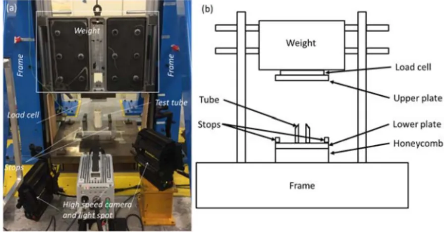
The operating principle of the assembly was as follows: the mass used (180 kg) was calculated so that 175
the kinetic energy available during the impact was significantly greater than the energy necessary to crush 176
85 mm of the tube. We thus obtained a test with an almost constant crushing speed. To stop the crushing 177
after approximately 85 mm, a stop system was used, which allowed the excess energy to be transferred 178
into an absorber (Nomex honeycomb block) located under the sample (Fig. 4). 179
180
Fig. 4: (a) Overview photograph of the dynamic testing setup, (b) Schematic representation 181
A force sensor located between the mass and the upper crushing plate made it possible to obtain the 182
crushing force with an acquisition frequency of 1 MHz. The displacement was calculated by double 183
integration of the force from knowledge of the initial speed given by an optical sensor. No filtering was 184
performed for data extraction. The high speed camera and the force signal were synchronized in order to 185
be able to link the images of the crushing front with the force-displacement curve. A redundant calculation 186
of displacement was also carried out using the camera images for a few samples to verify the accuracy 187
of the double integration method. 188
3. Results and discussion 189
All data are available in Table. 2 and Force-displacement curves for the static response are shown in Fig 190
5. 191
10 192
Fig. 5: Static force-displacement curves for tubes (a) [06] (b) [90/04/90] (c) [04/902] (d) [902/02/902]
193
g mm N mm N / J J J/g
Mass Thickness Fmax Lplateau Fplateau CFE EAplateau EAtot_80mm SEAplateau
St at ic te st s [06] - #1 77.4 6.7 36 403 / / / / / / [06] - #2 76.0 6.8 40 667 / / / / / / [06] - #3 75.3 6.6 38 067 / / / / / / Average 76.2 6.7 38 379 / / / / / / Standard deviation 1.07 0.09 2 149 / / / / / / [90/04/90] - #1 76.9 6.9 31 722 74.9 17 039 0.54 1 276 1 368 25.4 [90/04/90] - #2 77.8 6.9 30 220 77.6 24 092 0.80 1 869 1 858 35.5 [90/04/90] - #3 74.9 6.7 27 569 78.1 21 926 0.80 1 712 1 670 33.8 Average 76.6 6.8 29 837 76.9 21 019 0.71 1 619 1 632 31.6 Standard deviation 1.8 0.10 2 103 1.7 3 613 0.15 307 247 5.4 [902/02/902] - #1 70.6 6.7 17 798 68.9 14 592 0.82 1 005 1 154 22.2 [902/02/902] - #2 73.1 6.6 19 541 64.2 10 312 0.53 662 923 16.3 [902/02/902] - #3 75.7 6.8 18 514 53.7 9 542 0.52 512 866 15.6 Average 73.1 6.7 19 403 62.2 11 482 0.62 726 981 18.0 Standard deviation 2.55 0.11 876 7.18 2 721 0.17 253 152 3.6 [04/902] - #1 73.5 6.5 28 311 55.3 12 680 0.45 701 1 241 19.9 [04/902] - #2 73.3 6.5 27 581 53.9 16 779 0.61 905 1 400 26.4 [04/902] - #3 72.4 6.6 22 039 56.7 10 991 0.50 624 939 17.5 Average 73.0 6.6 25 977 55.3 13 483 0.52 743 1 193 21.3 Standard deviation 0.59 0.01 3 430 1.4 2 976 0.08 145 234 4.6 Dynamic tests [90/04/90] - #1 72.0 6.5 41 601 51.5 14 454 0.35 744 1 462 23.2 [90/04/90] - #2 72.5 6.3 45 213 54.9 14 515 0.32 797 1 428 23.1 [90/04/90] - #3 71.0 6.3 44 762 54.0 18 997 0.42 1 025 1 705 31.0 [90/04/90] - #4 72.7 6.3 44 947 55.9 21 143 0.47 1 183 1 759 33.7 [90/04/90] - #5 75.4 6.4 46 717 55.8 22 716 0.49 1 267 1 842 34.9 [90/04/90] - #6 73.2 6.7 47 267 55.2 15 811 0.34 873 1 512 24.9 Average 73.7 6.5 45 084 54.6 17 939 0.40 982 1 618 28.5 Standard deviation 1.44 0.16 1 951 0.4 3 538 0.07 212 173 5.4
Table. 2: Static and Dynamic test results.
194
11 3.1. Static crushing
196
3.1.1. Results for [06] Tubes. 197
The first damage corresponded to the appearance of longitudinal cracking along the fibres after the peak 198
load (Fig. 5 (a)). These cracks cut the tube into several sections (Fig. 6). Then each section began to 199
bend until it broke. The longitudinal crack spread over a large part of the tube, leading to a total loss of 200
stiffness of the tube and marking a crushing force close to 0. For these types of tubes, the absence of a 201
plateau is to be noted and, therefore, energy absorption performance is difficult to exploit and the 202
expression does not necessarily have a clear meaning (Fig. 5 (a)). Delamination between layers also 203
occurred, and fragmentation could also be observed following these failures in fibres at 0° stressed under 204
bending (Fig. 6). It generated the formation of bundles, five large ones (almost half the length of the tube) 205
being counted for tubes # 1 and # 3, and 6 for tube # 2. This failure mode was observed on the three 206
tubes and was repeated although certain cracks did not start to form at the same time, which explains the 207
shift in the force-displacement curves (Fig. 5 (a)). However, this is a very unstable mode of failure and 208
results in oscillations generating a small amount of absorbed energy due to the force falling to 0 N. For 209
this configuration, the energy absorption is not optimal. 210
211
Fig. 6:Failure patterns of [06] tubes under a crush displacement of 40 mm and post-mortem patterns.
12 213
3.1.2. Results for [90/04/90] Tubes. 214
The advantage of this configuration was that it permitted observation of the influence of the orientation of 215
the outer and inner layers at 90°, which creates a confinement of the inner layers at 0°. For the first tube 216
(# 1) failure initiation occurred in its middle (Fig. 7 (a)). For the other two other tubes (# 2 and # 3), folds 217
occurred in an asymmetric manner. Once the first fold was created, the tube returned to its initial 218
configuration and could sustain crushing on a portion of the tube that had not yet been damaged. The first 219
fold appeared as soon as the chamfer was crushed. During the crushing and because of the creation of 220
the folds, the fibres at 90° broke and the fibres at 0° bent until they ruptured. The failure modes of the 221
three tubes was quite similar: even though the damage of tube # 1 began halfway up the tube, the same 222
mode of failure occurred during the crushing, which explains the same level of force obtained at the end 223
of the compression. However, the number of folds was not identical in the three tubes. 224
225
Fig. 7: (a) Failure mode of tube [90/04/90] - #1 after 20 mm of crushing; (b) tube [90/04/90] - #2 after 32 mm
226
of crushing and fold creation; (c) tube [90/04/90] - #3 post-mortem pattern
227
The resulting failure mode can be compared to the diamond failure mode [40-42] in tubes made of metallic 228
material, for example aluminium (Fig. 1 (a)), or Kevlar-epoxy composites (Fig. 1 (b)). 229
The force-displacement curve (Fig. 5 (b)) exhibits a load peak followed by the first damage. In 230
configuration [90/04/90], unlike configuration [06], a plateau occurs after the load peak, except for tube #1. 231
For this tube, as already mentioned, the initiation of failure occurred in the middle. So, the first fold did not 232
form from the start of the crushing and was observed later, with a drop in force at the level of the plateau 233
13
between about 20 and 50 mm. Then, an increase in the force was observed up to the plateau level for 234
tubes # 2 and # 3. For wood, introducing fibres at 90° helped to stabilize the crushing by confining the 235
fibres at 0°. The stabilization of the crushing linked to the layers at 90° thus prevented transverse 236
longitudinal cracks, made it possible to obtain a plateau on the force-displacement curve (non-existent for 237
the tubes [06]) and significantly increased the energy absorbed (1 619 J) and the SEA (31.6 J / g). These 238
tests also showed a relatively low initial peak force compared to the plateau value, resulting in a relatively 239
high CFE (0.71) 240
3.1.3. Results for [902/02/902] Tubes. 241
This configuration showed the influence of the number of layers at 90° on energy absorption. The initiation 242
of damage on tubes # 1 and # 3 was unstable. In fact, it was probably due to an interaction between local 243
buckling at the centre of tubes and overall buckling (Fig. 8). The ruin of tube # 1 spread with 244
interpenetration while the ruin of tube # 3 spread on the opposite side of the chamfer. The damage 245
initiation in tube # 2 occurred as expected on the chamfered side. Thereafter the failure mode of these 246
tubes was similar to that of tubes [90/04/90] with formation of folds (Fig. 8). Nevertheless, the folding 247
propagation was stable with regard to the force-displacement curve of each of the tubes (Fig. 5 (d)). 248
However, there were about half as many folds on the configuration [90/04/90] (discussed in section 3.1.5), 249
which explains the smaller number of oscillations on the force displacement curve. As with composite 250
laminates, the number of 0° plies was important. Therefore, the energy absorbed and the SEA of these 251
tubes (1 619 J and 31.6 J/g) decreased with respect to the configuration [90/04/90] (726 J and 18 J /g). 252
The CFE also decreased slightly from 0.71 to 0.62. 253
14 255
Fig. 8: First line: failure initiation of tubes [902/02/902] after 23.8 mm of crushing; second line: failure
256
patterns after 60 mm of crushing and, last line: post-mortem views. 257
3.1.4. Results for [04/902] tubes. 258
The objective for this last configuration was to observe the influence of the position of the layers at 90°. 259
Fold formation was again present for the mode of ruin of these tubes. At the beginning of the crushing, it 260
was found that the tubes lost their cylindrical geometry, which became oval, corresponding to the 261
formation of a fold in diamond mode, probably because of the unsymmetrical stacking, which created 262
local membrane/bending coupling. At a given height of the tube and on the same plane, two inside folds 263
were created facing each other while, perpendicularly, there were also two folds facing each other, but 264
outwards (Fig. 9). So, on this same plane, 4 folds were visible. 265
15 266
Fig. 9: Initiation of failure mode of [04/902] tubes. (a) #1 pristine, (b) #1, (c) #2 (d) #3 between 26 and 27mm
267
of crushing. 268
The diamond shape appeared at the start of crushing and corresponded to the formation of the plateau 269
on the force-displacement curve (around 30 mm of crushing) (Fig. 5 (c)). Furthermore, the number of folds 270
for this configuration was almost twice that with the [90/04/90] configuration and, again, can explain why 271
the oscillations on the force-displacement curve were less marked. The influence of the position of the 272
layer at 90° is not negligible and has its importance for the amount of energy absorbed. From the 273
configuration [90/04/90] to configuration [04/902], an average loss of 87.6 J for EA and 10.3 J/g for SEA 274
should be noted. The CFE dropped by 0.19. Having a 90° fold inside and outside clearly stabilized the 275
fibres at 0° and induced better confinement than in the case where folds were located outside only. 276
3.1.5. Discussion on the crushing patterns (static). 277
Having no layers oriented at 90°, the tubes [06] crushed in a very unstable way. The initiation was marked 278
by the appearance of bundles characterizing cracking between the fibres in the longitudinal direction. The 279
propagation of splitting in the direction of the tube led to a significant loss of stiffness of the tube, cutting 280
the tubes into bundles (Fig. 6). As the tubes no longer satisfied the structural criterion, the initial crushing 281
length of 90 mm was not respected; the test was interrupted on tubes # 1 and # 2 (zero compression 282
force). With a layer oriented at 90°, crushing was stabilized, and a gain in absorbed energy was observed. 283
16
Nevertheless, it is difficult to analyse the situation by looking only at the outer pattern of the tubes from a 284
macroscopic point of view. Therefore, some tubes were cut lengthwise into two half-tubes to gain access 285
to more information about their failure modes (Fig. 10 (a)). 286
Some differences between the two configurations [90/04/90] and [902/02/902] were still present. The
287
number of folds was higher for the [90/04/90] tubes (Fig. 10 (a)). Other authors [43] have found that
288
inserting foam on thin-walled tubes reduces the buckling length of the folds, thereby increasing their 289
number, and also increases the crushing force. In our case, we can assume that the presence of more 290
fibres at 0° required a greater crushing force, which generated an increase in the number of folds and 291
therefore more energy absorbed. 292
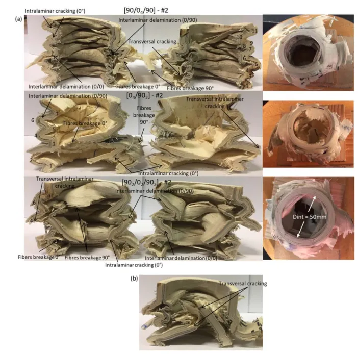
For [90/04/90] tubes, transversal cracking (i.e. in the thickness of the tube) was visible in the wall of the 293
tube # 1 (Fig.10 (b)). This crack may explain the drop in the crushing force in the plate after the peak load. 294
Such cracks were also found in the other two configurations [04/902] and [902/02/902]. For tubes [90/04/90] 295
# 2 and # 3 and [902/02/902] - # 3, the fibre breakages observed in layers oriented at 90° allowed the 296
appearance of a vertical crack creating petals, although the global failure mode was by local buckling (Fig. 297
10 (a)). In Fig. 10, some 0° layers can be seen to be broken, probably because of the high bending 298
stresses due to the local hinges. However, most of the time, the wooden layers support large local 299
deformations. Delaminations are also observed everywhere, mostly at the 0°/90° interface but it is hard 300
to explain their onset in the failure scenario (before or after the peak load) in this post-mortem analysis. 301
Finally, an elastic return was observed in the length of the tubes. Since the tubes were not 100% 302
damaged, some structural integrity of the tubes remained. Therefore, the tubes unfolded after the release 303
of the compression force. The elastic return is not negligible: the remaining length of the crushed tubes 304
should have been 30 mm, whereas a residual length of around 60 mm was measured. 305
Finally, the overall failure patterns of each configuration having two of the layers oriented at 90° are very 306
similar to each other (local buckling formation, delamination 0/90, etc.) but there are many discrepancies, 307
which can be attributed to several parameters: 308
17
The fact that the tubes were manufactured manually may have introduced sources of variability: 309
the process could have led to a deviation of the angles of the fibres (0° or 90°), due to either the 310
cutting or the winding of the veneers, and the bonding could exhibit some defects. 311
In addition to being anisotropic, wood is a very heterogeneous material. It therefore shows 312
considerable variability in its properties: humidity, density, spring / winter wood, etc. 313
314
Fig. 10: (a) Static crushing modes – the left and right pictures are from the same sample. The figures on 315
the pictures are used to count the number of folds. (b) Delamination, photo of half-tube [90/04/90] #1
316 317 318 319
18 3.2. Dynamic crushing
320
The configuration of the tubes having the best characteristics in terms of energy absorption (EA, SEA and 321
CFE) in static tests was kept for the dynamic tests. Six tubes [90/04/90] were crushed in order to see the 322
difference in behaviour and energy absorption in static and dynamic situations. Results are given in Tab. 323
1 and the six dynamic crushing force-displacement curves of the tubes [90/04/90] are shown in Fig.11. 324
The general shape of the force-displacement curves is identical to the static case, with the same three 325
phases of initiation, transition and plateau. In terms of performance, two groups of tubes can be identified: 326
tubes 1, 2 and 6 have a SEA between 23.1 and 24.9 J / g while tubes 3, 4 and 5 have a SEA of 31 to 34.9 327
J / g. From the manufacturing point of view, no significant defects that could explain this performance gap 328
were observed from one tube to another. Therefore, this difference can be attributed, as in static crushing, 329
to the variability of the material. 330
331
Fig. 11: Dynamic force-displacement curves for tubes [90/04/90]
19
The dynamic failure pattern is almost the same on the six specimens (Fig. 12). 333
334
Fig. 12: Dynamic crushing modes of all 6 tubes [90/04/90]
335
Crushing is initiated by the formation of a local fold on the side of the chamfer, recalling the mode of ruin 336
of the tubes in static tests. The formation of the folds generates delaminations, intralaminar cracking and 337
probably wood fibre failures, which divide the tubes into bundles (Fig. 13). 338
20 339
Fig. 13: Failure scenario of tube #5 340
The failures then propagate due to local bending until local fragmentation forms macroscopic debris (Fig. 341
13). Small debris (almost dust) was also observed. The separation of the tube into a bundle and the 342
bending of the latter is analogous to splaying. The observation of macroscopic debris allowed us to note 343
that splaying did not occur in an identical way for all the tubes. By cutting the tubes it was possible to 344
provide a more precise explanation of the ruin of the tubes used in dynamic tests (Fig. 14). The presence 345
of debris during the crushing is responsible for the splaying as the debris forces the upper intact part to 346
separate and splay. When crushing different configurations of carbon-epoxy fibre plates, Guillon [23] also 347
found an accumulation of debris causing a damaged flare. Depending on the position, the debris will 348
condition the number of folds that splay inward or outward (Fig. 15). 349
The formation of bundles and their bending allow the creation of petals. The formation of petals has been 350
observed on crushed CFRP tubes for a long time [27] (Fig. 15). Splaying is also initiated by an interlaminar 351
crack that dissociates the tubes into bundles. Again, these bundles bend and then form the petals. The 352
21
geometric shape of the petals (length, width, thickness) are influenced by many parameters such as 353
stiffness, ultimate stresses, tube diameter, and wall thickness. 354
355
Fig. 14: Tube #5 cross section 356
357
Fig. 15: Petal failure mode for poplar wood. 358
359 360
22 3.3. Comparison of static and dynamic crushing 361
All the test curves for the [90/04/90] specimens are merged in Fig. 16. 362
363
Fig. 16: (a) Comparison of static and dynamic crush curves (S-for static and D- for dynamic) (b) Zoom on 364
the transition region 365
The first major difference between the static and dynamic curves is the value of the peak load: it is much 366
higher in dynamic (45,084 N) than in static tests (29,837 N). The second difference is the apparent 367
stiffness of the tube during pseudo-linear loading. The dynamic stiffness (pseudo-linear slope) is 88% 368
higher than the static stiffness (515 MPa and 970 MPa for static and dynamic, average values). These 369
23
two differences have also been found in drop weight tests on poplar [13] and in Hopkinson tests on beech 370
and spruce [10,11]. The transition phase between the peak load and the plateau is also more marked in 371
dynamic than in static crushing. In static situations, as soon as the peak load passes, the plateau is 372
present. Although the plateau can be decreasing, it is obtained between 5 and 10 mm in static (Fig. 16 373
(b)). The peak load is obtained at substantially the same displacement as in static tests, except that the 374
dynamic transition phase ends at around 15 mm (12.5 mm for the shortest transition phase, obtained for 375
tube 4). The end of the pseudo-linear phase, corresponding to the moment when the first damage occurs 376
and when there is a fall in force, is around 6-7 mm of displacement for static or dynamic tests. This value 377
corresponds closely to the value of the height of the chamfer, which therefore appears to be responsible 378
for the end of this phase. 379
In addition, the difference between the maximum force and the minimum force observed on the plate is 380
greater in dynamic loading (up to 15,600 N) than in static (11,700 N if the unstable crushing of tube # 1 is 381
omitted). On the other hand, due to the increase in the peak load, the CFE ratio decreases in dynamic 382
loading, from 0.71 to 0.40. Finally, the other performance levels (Tab. 1), whether for the average force 383
(21,019 N in static - 17,939 N in dynamic), the energy absorbed (1,632 J in static - 1,618 J dynamic) or 384
the SEA (31.6 J/g static - 28.5 J/g dynamic), are almost identical between static and dynamic crushing. 385
During Hopkinson or weight-down crushing to assess the effect of the speed of the stress on the behaviour 386
of the wood material [9–13], it was found that the average stress increased with the dynamic effect, 387
causing an increase of the energy absorbed and therefore of the SEA. 388
In this study, the dynamic failure mode differs from the static one. In static, the crushing is stable with 389
creation of folds while the dynamic tubes have a failure initiation identical to the static (formation of a fold) 390
but subsequent propagation is by splaying and fragmentation creating macroscopic and microscopic 391
debris (Fig. 17). 392
24 393
Fig. 17: Comparison of the failure scenario between a static and a dynamic tests at iso-displacement 394
[90/04/90] - #2 specimen for static – [90/04/90] - #1 specimen for dynamic.
395
The change in static-dynamic failure mode can be explained by the viscoelastic nature of wood. Its 396
constituents (lignin, cellulose, and hemicellulose) have a behaviour that changes with the strain rate. This 397
can be shown by the increase in the apparent stiffness (mentioned above). Therefore, in static crushing, 398
the wood has a ductile character, which enables folds to form, while in dynamic, the fragile character 399
takes over and generates a fragile mode with the creation of multiple macroscopic debris.In addition, the
400
glue can have an important influence. It is thus difficult to conclude that (Fplateau, EAtot_80mm, SEAplateau) 401
are almost identical between the static and the dynamic regimes. 402
The transition from static to dynamic crushing is also an issue for composite materials, particularly as far 403
as the evolution of performances is concerned. Do they increase or decrease in dynamic crushing? The 404
25
works of Farley and Jones [31] attribute the increase in crash characteristics to the dependence of material 405
properties on the strain rate, especially for Kevlar fibres but also for the matrix. In their study, Mamalis et 406
al. [44] obtained different failure modes between static and dynamic loading, thus explaining the variation 407
in performance. McGregor et al. [45] attribute the lower performance in dynamic loading to the fact that 408
there is more transverse shear in the corners of the tubes in dynamic failure, associated with a 409
deterioration of the fibre/matrix interface and a fragile behaviour of the matrix. David et al. [46] observed 410
that the length of the petals was longer in static loading, leading to more cracking, and increased friction 411
in delamination and at the interface of the plates. In dynamic loading, the matrix becomes more fragile, 412
its stiffness increases and its toughness decreases, leading to a reduction in the splaying lengths. Finally, 413
Brighton et al. [47] attribute the decrease in dynamic properties to the radius of curvature of the petals, 414
which is smaller in static and leads to more damage. 415
416
3.4 Summary 417
According to the literature, in terms of SEA, wood shows poorer performance than composite or metallic 418
materials but remains interesting thanks to its carbon footprint, its recyclability, and its material cost, which 419
is very low compared to those of composite materials (the cost of poplar veneer I214 in 1240x2200 mm2 420
format is about € 2.5/veneer while that of CFRP is € 34/m2 on average). The SEA of tubes made of carbon 421
fibre composite materials with an epoxy resin ranges from 38 J/g [48], with an internal diameter of 50 mm 422
and a ±45° and 0° stacking sequence, to 140 J/g, with the same internal diameter but a [(0/90)/(0)8/(0/90)]
423
sequence [49] (Fig. 18) and can reach 227 J/g in presence of PEEK resin with a tube 55 mm in diameter 424
and 2.66 mm thick [50]. Glass fibres have a slightly lower potential, from 21 J/g [51] and 87 J/g [52] for 425
semi-hexagonal profiles with unidirectional plies oriented at 0° and 90° to a 39.3 mm diameter tube of 3 426
mm thickness, to a maximum of 195 J/g for a PEEK resin [53] obtained on a 55 mm diameter tube with a 427
thickness of 2.65 mm and fibre orientation of ±10°. If we consider metallic materials, the SEA can vary 428
from 34 to 88 J/g [54,55], the maximum SEA being obtained with Al 6061 on a 38.1 mm diameter tube 429
26
with 2.4 mm thickness. Flax tubes ranging from 36 mm to 82 mm in diameter have shown an interesting 430
potential varying from 7 to 42 J/g [30]. Researchers have also tried to recycle wood chips by integrating 431
them as core material in PVC (external diameter of 84 mm with 2.3 mm wall thickness) and aluminium 432
(38 mm inner diameter and 1.2 mm wall thickness) tubes, and have obtained SEA values between 9 and 433
17 J/g [56, 57]. Finally, with 100 x 100 x 15.5 mm3 plates, as a core material associated with glass fibre
434
skins, solid balsa has shown a SEA of between 12 and 20 J/g depending on the triggers used [58]. 435
436 437
Fig. 18: SEA of various materials 438
4. Conclusions and perspectives 439
Static and dynamic crushing performances are quite promising for a natural and environmentally friendly 440
material like wood. The tests have shown that: 441
Orienting all the poplar layers at 0° is not a good choice as it generates an unstable failure mode 442
with very low energy absorption. 443
As soon as a 90° layer is present outside and inside (or only outside), this produces a "hoop" 444
effect and the tube will have a stable crushing mode with a plateau whatever the configuration. 445
27
Too many layers at 90° are not necessarily effective in terms of the amount of energy absorbed: 446
loss of 43% of SEA between the configurations [902/02/902] and [90/04/90]. 447
The position of the layers at 90° also has an influence on the amount of energy absorbed. In fact, 448
in the configurations [04/902] and [90/04/90], a gain of 33% of SEA is obtained by completely 449
confining the layers at 0°. The "hoop" effect found for composite materials is also found here. 450
In terms of static failure modes, the presence of 90° plies allows successive and asymmetrical 451
formation of folds generated by local buckling. In dynamic tests, the failure mode changes, with 452
the apparition of splaying and fragmentation generating macroscopic and microscopic debris. 453
The best of the static configurations studied, and used in dynamic tests, was [90/04/90], which 454
reached an average absorbed energy of 1 632 J in static and 1 618 J in dynamic configurations, 455
with an average SEA of 30 J/g. 456
In dynamic testing, the peak load and the stiffness are significantly increased and the SEA is 457
almost identical. The CFE is also significantly lower in dynamic. Finally, the transition phase is 458
more significant in dynamic than in static loading. 459
These results are very promising for the future of the use of wood-based eco-materials for crash 460
applications. Although the levels of SEA reached are a quarter of those obtained on the best composite 461
materials, the composite materials are 40 times as expensive as the wood-based ones. In addition, the 462
poplar selected for this study is one of the least mechanically efficient woods and it is likely that better 463
quality woods would have higher SEA. In addition, to better understand the crush behaviour of wood 464
tubes, advanced modelling is necessary. A very limited number of papers have dealt with the subject [17] 465
so far and a research effort has to be made to develop material damage models for wood plies, together 466
with efficient modelling strategies. 467
468
5. Acknowledgements 469
28
The authors thank the French Government for providing financial support and the Garnica company for 470
providing I214 veneers for this study. 471
6. References 472
[1] Laboratory FP. Wood Handbook Wood as an Engineering Material. United States Department of 473
Agriculture Forest Service; 2010. 474
475
[2] Bergman R, Puettmann M, Taylor A, Skog KE. The Carbon Impacts of Wood Products. Forest Products 476
Journal: 2014;64:220-231. https://doi.org/10.13073/FPJ-D-14-00047 477
478
[3] Bucci V, Corigliano P, Crupi V, Epasto G, Guglielmino E, Marinò A. Experimental investigation on Iroko 479
wood used in shipbuilding. Proceedings of the Institution of Mechanical Engineers, Part C: Journal of 480
Mechanical Engineering Science 2017;231:128–39. https://doi.org/10.1177/0954406216674495. 481
482
[4] Zenkerts D. The handbook of sandwich construction. Engineering Materials Advisory Services Ltd. 483
United Kingdom: 1997. 484
485
[5] Susainathan J, Eyma F, De Luycker E, Cantarel A, Castanie B. Manufacturing and quasi-static bending 486
behavior of wood-based sandwich structures. Composite Structures 2017;182:487–504. 487
https://doi.org/10.1016/j.compstruct.2017.09.034 488
489
[6] Butler N. Computer modelling of wood-filled impact limiters. Nuclear Engineering and Design 490
1994;150:417 424; https://doi.org/10.1016/0029-5493(94)90161-9 491
492
[7] CANPLY. Eléments de calcul du contreplaqué 1997. 493
494
[8] Johnson W. Historical and Present-Day References Concerning Impact on Wood. International Journal 495
on impact Engineering 1986; 4:161-174. https://doi.org/10.1016/0734-743X(86)90003-5. 496
497
[9] Reid S.R., Peng C. Dynamic uniaxial crushing of wood. International Journal on impact Engineering 498
1997; 19:531-570. https://doi.org/10.1016/S0734-743X(97)00016-X 499
500
[10] Wouts J, Haugou G, Oudjene M, Morvan H, Coutellier D. Strain rate effects on the compressive 501
response of wood and energy absorption capabillities - Part B: Experimental investigation under rigid 502
lateral confinement. Composite Structures 2018. https://doi.org/10.1016/j.compstruct.2018.07.001. 503
504
[11] Wouts J, Haugou G, Oudjene M, Coutellier D, Morvan H. Strain rate effects on the compressive 505
response of wood and energy absorption capabilities – Part A: Experimental investigations. Composite 506
Structures 2016;149:315–328. https://doi.org/10.1016/j.compstruct.2016.03.058. 507
508
[12] Pang S, Liang Y, Tao W, Liu Y, Huan S, Qin H. Effect of the Strain Rate and Fiber Direction on the 509
Dynamic Mechanical Properties of Beech Wood. Forests 2019, 10(10), 881; 510
https://doi.org/10.3390/f10100881 511
512
[13] Adalian C, Morlier P. “WOOD MODEL” for the dynamic behaviour of wood in multiaxial compression. 513
Holz Als Roh- Und Werkstoff 2002;60:433–9. https://doi.org/10.1007/s00107-002-0333-x. 514
29
[14] Demircioğlu TK, Balıkoğlu F, Inal O, Arslan N, Ataş A. Experimental investigation on low-velocity 516
impact response of woodskinned sandwich composites with different core configurations. Materials Today 517
Communications 2018;17:31-39. https://doi.org/10.1016/j.mtcomm.2018.08.003 518
519
[15] Smardzewski J. Wooden sandwich panels with prismatic core – Energy absorbing capabilities; 520
Composite Structures 2019;230:111535. https://doi.org/10.1016/j.compstruct.2019.111535 521
522
[16] Susainathan, J., Eyma, F., De Luycker, E., Cantarel, A., Castanie, B. Experimental investigation of 523
impact behavior of wood-based sandwich structures. Composites Part A: Applied Science and 524
Manufacturing 2018;109,10-19. https://doi.org/10.1016/j.compositesa.2018.02.029 525
526
[17] Susainathan, J., Eyma, F., De Luycker, E., Cantarel, A., Castanie, B. Numerical modeling of impact 527
on wood-based sandwich structures. Mechanics of Advanced Materials and Structures, on line, 528
https://doi.org/10.1080/15376494.2018.1519619 529
530
[18] Susainathan J, Eyma F, De Luycker E, Cantarel A, Bouvet C, Castanie B. Experimental investigation 531
of compression and compression after impact of wood-based sandwich structures. Composite Structures 532
2019;220:236–49. https://doi.org/10.1016/j.compstruct.2019.03.095. 533
534
[19] Nguyen XT, Hou S, Liu T, Han X. A potential natural energy absorption material – Coconut mesocarp: Part A: 535
Experimental investigations on mechanical properties. International journal of mechanical sciences, 2016, 115-116: 536
564-573. https://doi.org/10.1016/j.ijmecsci.2016.07.017 537
538
[20] Liu T, Hou S, Nguyen X, Han X. Energy absorption characteristics of sandwich structures with composite 539
sheets and bio coconut core. Composites Part B: Engineering, 2017, 114: 328-338. 540
https://doi.org/10.1016/j.compositesb.2017.01.035 541
542
[21] Lu C, Hou S, Zhang Z, Chen J, Li Q, Han X. The mystery of coconut overturns the crashworthiness design of 543
composite materials International journal of mechanical sciences, 2020, 168: 105244. 544
https://doi.org/10.1016/j.ijmecsci.2019.105244 545
546
[22] Neveu F, Castanié B, Olivier P. The GAP methodology: A new way to design composite structures 547
Materials & Design 2019;172:107755. https://doi.org/10.1016/j.matdes.2019.107755 548
549
[23] Guillon D. Etude des mécanismes d’absorption d’énergie lors de l’écrasement progressif de 550
structures composites à base de fibre de carbone. PhD Thesis. Institut Supérieur de l’Aéronautique et de 551
l’Espace, ISAE, Ecole doctorale : Mécanique, énergétique, génie civil et procédés, 2008. 552
553
[24] Kim J-S, Yoon H-J, Shin K-B. A study on crushing behaviors of composite circular tubes with different 554
reinforcing fibers. International Journal of Impact Engineering 2011;38:198-207. 555
https://doi.org/10.1016/j.ijimpeng.2010.11.007 556
557
[25] Ataabadi PB, Karagiozova D, Alves M. Crushing and energy absorption mechanisms of carbon fiber-558
epoxy tubes under axial impact. International Journal of Impact Engineering 2019;131:74-189. 559
https://doi.org/10.1016/j.ijimpeng.2019.03.006 560
561
[26] Wang Y, Feng J, Wu J, Hu D. Effects of fiber orientation and wall thickness on energy absorption 562
characteristics of carbon-reinforced composite tubes under different loading conditions. Composite 563
Structures 2016;153:356–368. https://doi.org/10.1016/j.compstruct.2016.06.033. 564
30
[27] Hamada H, Coppola JC, Hull D, Maekawa Z, Sato H. Comparison of energy absorption of 566
carbon/epoxy and carbon/PEEK composite tubes. Composites 1992;23:245–252. 567
https://doi.org/10.1016/0010-4361(92)90184-v. 568
569
[28] Song H-W, Du X-W, Zhao G-F. Energy Absorption Behavior of Double-Chamfer Triggered Glass/Epoxy 570
Circular Tubes. J Compos Mater 2002;36:2183–98. https://doi.org/10.1177/0021998302036018515. 571
572
[29] Hu D, Zhang C, Ma X, Song B. Effect of fiber orientation on energy absorption characteristics of glass 573
cloth/epoxy composite tubes under axial quasi-static and impact crushing condition. Composites Part A: 574
Applied Science and Manufacturing 2016;90:489–501. 575
https://doi.org/10.1016/j.compositesa.2016.08.017. 576
577
[30] Yan L, Chouw N. Crashworthiness characteristics of flax fibre reinforced epoxy tubes for energy 578
absorption application. Materials & Design 2013;51:629–640. 579
https://doi.org/10.1016/j.matdes.2013.04.014. 580
581
[31] Farley GL, Jones MR. Energy absorption capability of composite tubes and beams. PhD Thesis. 582
NASA TM 10634, 1989. 583
584
[32] Hull D. A unified approach to progressive crushing of fibre-reinforced composite tubes. Composites 585
Science and Technology 1991;40:377–421. https://doi.org/10.1016/0266-3538(91)90031-j. 586
587
[33] Kindervater CM. Energy absorption of composites as an aspect of aircraft structural crash-resistance. 588
Developments in the Science and Technology of Composite Materials, Springer Netherlands; 1990, p. 589
643–651. https://doi.org/10.1007/978-94-009-0787-4_89. 590
591
[34] Thornton PH, Edwards PJ. Energy absorption in composite tubes. Journal of Composite Materials 592
1982;16:521–545. https://doi.org/10.1177/002199838201600606. 593
594
[35] Garnica. http://www.garnica.one/en. Accessed 02 April 2020 595
596
[36] Baldassino N, Zanon P, Zanuttini R. Determining mechanical properties and main characteristic 597
values of Poplar plywood by medium-sized test pieces . Materials and Structures 1998;31(1): 64-67. 598
https://doi.org/10.1007/BF02486416. 599
600
[37] Fang CH, Mariotti N, Cloutier A, Koubaa A, Blanchet P. Densification of Wood Veneers by 601
Compression Combined with Heat and Steam. European Journal of Wood and Wood Products 2012; 70 602
(1-3):155-63. https://doi.org/10.1007/s00107-011-0524-4. 603
604 605
[38] Siromani D, Henderson G, Mikita D, Mirarchi K, Park R, Smolko J, et al. An experimental study on 606
the effect of failure trigger mechanisms on the energy absorption capability of CFRP tubes under axial 607
compression. Composites Part A: Applied Science and Manufacturing 2014;64:25–35. 608
https://doi.org/10.1016/j.compositesa.2014.04.019. 609
610
[39] Blazy J-S. Comportement mécanique des mousses d’aluminium : caractérisations experimentales 611
sous sollicitations complexes et simulations numériques dans le cadre de l’élasto-plasticité compressible. 612
PhD Thesis. Ecole Nationale Supérieure des Mines de Paris, 2003. 613
31
[40] Andrews KRF, England GL, Ghani E. Classification of the axial collapse of cylindrical tubes under 615
quasi-static loading. International Journal of Mechanical Sciences 1983;25:687–696. 616
https://doi.org/10.1016/0020-7403(83)90076-0. 617
618
[41] Al Galib D, Limam A. Experimental and numerical investigation of static and dynamic axial crushing 619
of circular aluminum tubes. Thin-Walled Structures 2004;42:1103–37. 620
https://doi.org/10.1016/j.tws.2004.03.001. 621
622
[42] Dubey DD, Vizzini AJ. Testing Methods for Energy Absorption of Kevlar/Epoxy. J Am Helicopter Soc 623
1999;44:179–87. https://doi.org/10.4050/JAHS.44.179. 624
625
[43] Baroutaji A, Sajjia M, Olabi A-G. On the recent crashworthiness performance of thin walled energy 626
absorbers: recent advances and future developments. Thin-Walled Strucutres 118 137-163 2017. 627
628
[44] Mamalis AG, Manolakos DE, Ioannidis MB, Papapostolou DP. On the response of thin-walled CFRP 629
composite tubular components subjected to static and dynamic axial compressive loading: experimental. 630
Composite Structures 2005;69:407–420. https://doi.org/10.1016/j.compstruct.2004.07.021. 631
632
[45] McGregor C, Vaziri R, Poursartip A, Xiao X. Axial crushing of triaxially braided composite tubes at 633
quasi-static and dynamic rates. Composite Structures 2016;157:197–206. 634
https://doi.org/10.1016/j.compstruct.2016.08.035. 635
636
[46] David M, Johnson AF, Voggenreiter H. Analysis of Crushing Response of Composite Crashworthy 637
Structures. Appl Compos Mater 2013;20:773–87. https://doi.org/10.1007/s10443-012-9301-8. 638
639
[47] Brighton A, Forrest M, Starbuck M, Erdman D, Fox B. Strain Rate Effects on the Energy Absorption 640
of Rapidly Manufactured Composite Tubes. Journal of Composite Materials 2009;43:2183–200. 641
https://doi.org/10.1177/0021998309344646. 642
643
[48] Schultz MR. Energy absorption capacity of graphite-epoxy composite tubes. Master’s Thesis. Virginia 644
Polytechnic Institute and State University, 1998. 645
646
[49] Chambe J, Bouvet C, Dorival O, Ferrero J. Energy absorption capacity of composite thin-wall circular 647
tubes under axial crushing with different trigger initiations. Journal of Composite Materials 648
2019:002199831987722. https://doi.org/10.1177/0021998319877221. 649
650
[50] Hamada H, Ramakrishna S. Scaling effects in the energy absorption of carbon-fiber/PEEK composite 651
tubes. Composites Science and Technology 1995;55:211–21. https://doi.org/10.1016/0266-652
3538(95)00081-X. 653
654
[51] Esnaola A, Ulacia I, Aretxabaleta L, Aurrekoetxea J, Gallego I. Quasi-static crush energy absorption 655
capability of E-glass/polyester and hybrid E-glass–basalt/polyester composite structures. Materials & 656
Design 2015;76:18–25. https://doi.org/10.1016/j.matdes.2015.03.044. 657
658
[52] Ochelski S, Gotowicki P. Experimental assessment of energy absorption capability of carbon-epoxy 659
and glass-epoxy composites. Composite Structures 2009;87:215–24. 660
https://doi.org/10.1016/j.compstruct.2008.01.010. 661
32
[53] Hamada H, Ramakrishna S. Effect of Fiber Material on the Energy Absorption Behavior of 663
Thermoplastic Composite Tubes. Journal of Thermoplastic Composite Materials 1996;9:259–79. 664
https://doi.org/10.1177/089270579600900304. 665
666
[54] Farley GL. Energy absorption of composite materials. Journal of Composite Materials 1983;17:267– 667
279. https://doi.org/10.1177/002199838301700307. 668
669
[55] Saito H, Chirwa EC, Inai R, Hamada H. Energy absorption of braiding pultrusion process composite 670
rods. Composite Structures 2002;55:407–417. https://doi.org/10.1016/s0263-8223(01)00160-x. 671
672
[56] Singace AA. Collapse behaviour of plastic tubes filled with wood sawdust. Thin-Walled Structures 673
2000;37:163–187. https://doi.org/10.1016/s0263-8231(00)00012-4. 674
675
[57] Kiran R, Khandelwal N, Tripathi P. Collapse behaviour and energy absorption of aluminium tubes 676
filled with wood sawdust. International Journal of Engineering Research and Reviews 2014. 677
678
[58] Lindstrom A, Hallstrom S. Energy absorption of SMC/balsa sandwich panels with geometrical 679
triggering features. Composite Structures 2010;92:2676–2684. 680
https://doi.org/10.1016/j.compstruct.2010.03.018. 681
![Fig. 1 : « Diamond » failure mode (a) AL6060 tube reproduced from [39]) (b) Kevlar/epoxy tube 90](https://thumb-eu.123doks.com/thumbv2/123doknet/12296280.323672/5.892.263.633.682.1055/fig-diamond-failure-mode-tube-reproduced-kevlar-epoxy.webp)
![Fig. 2: Pristine sample [0 4 /90 2 ] - #2 140 141 142 143 144 145 2.2. Static tests 146](https://thumb-eu.123doks.com/thumbv2/123doknet/12296280.323672/8.892.274.621.103.315/fig-pristine-sample-static-tests.webp)

![Fig. 5: Static force-displacement curves for tubes (a) [0 6 ] (b) [90/0 4 /90] (c) [0 4 /90 2 ] (d) [90 2 /0 2 /90 2 ]193](https://thumb-eu.123doks.com/thumbv2/123doknet/12296280.323672/11.892.104.784.104.440/fig-static-force-displacement-curves-tubes-b-c.webp)
![Fig. 6: Failure patterns of [0 6 ] tubes under a crush displacement of 40 mm and post-mortem patterns](https://thumb-eu.123doks.com/thumbv2/123doknet/12296280.323672/12.892.162.729.724.1103/fig-failure-patterns-tubes-crush-displacement-mortem-patterns.webp)
![Fig. 7: (a) Failure mode of tube [90/0 4 /90] - #1 after 20 mm of crushing; (b) tube [90/0 4 /90] - #2 after 32 mm 226](https://thumb-eu.123doks.com/thumbv2/123doknet/12296280.323672/13.892.113.778.578.790/fig-failure-mode-tube-mm-crushing-tube-mm.webp)
![Fig. 8: First line: failure initiation of tubes [90 2 /0 2 /90 2 ] after 23.8 mm of crushing; second line: failure 256](https://thumb-eu.123doks.com/thumbv2/123doknet/12296280.323672/15.892.171.725.103.537/fig-line-failure-initiation-tubes-crushing-second-failure.webp)
![Fig. 9: Initiation of failure mode of [0 4 /90 2 ] tubes. (a) #1 pristine, (b) #1, (c) #2 (d) #3 between 26 and 27mm 267](https://thumb-eu.123doks.com/thumbv2/123doknet/12296280.323672/16.892.120.771.105.441/fig-initiation-failure-mode-tubes-pristine-b-mm.webp)