COMPARISON OF GRADIENT-BASED AND GRADIENT-FREE
METHODS FOR OPTIMAL STACKING SEQUENCE OF
COMPOSITES
Michaël Bruyneel, Freddie Colsoul, Samih Zein LMS Samtech, A Siemens business
Liège Science Park Angleur 4031, Belgium
ABSTRACT
This paper deals with the solution of the optimal stacking sequence problem for laminated composite structures made of conventional plies oriented at 0°, 45°, 90° and -45°. A constraint of the optimization problem is to be able to take into account the classical design rules, such as a minimum amount of each kind of orientation must be present in the laminate, which moreover must be balanced and symmetric. Two optimization approaches are compared. The first one is based on a discrete formulation of the problem, which can directly solve the combinatorial optimization problem. In the second approach, continuous design variables are used, with a specific parameterization of the material properties based on a multi-phase topology optimization formulation. The efficiency of the approaches is compared on a representative test case, which consists in a panel submitted to buckling.
1.
INTRODUCTION
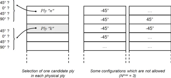
The problem of identifying the optimal stacking sequence in laminates has been investigated for a long time. In most practical applications, the candidate materials are restricted to -45°, 0°, 45° and 90° plies, which are the conventional orientations used in aeronautics [1]. In order to propose solutions which are relevant for industrial applications, the optimal stacking sequences must satisfy specific design rules, such as the laminate must be balanced and symmetric, there must be no more than Nmax successive plies with the same orientation in the laminate (Nmax is often equal
to 3 or 4), the transition between two plies must be at most of 45°, that is [0/90] and [45/-45] sequences are forbidden, and finally, minimum and maximum percentages of each possible orientation must exist. The design problem, with some undesired stacking sequences, is illustrated in Figure 1, where n is the total number of plies in the laminate.
In this paper, an optimization procedure based on multi-phase topology optimization is presented to determine the optimal stacking sequence of laminates made up of conventional plies oriented at -45°, 0°, 45 and 90°, taking into account the design rules. The formulation relies on the SFP parameterization [2] in which the discrete optimization problem is replaced by a continuous approach with a penalty to exclude intermediate values of the design variables. In this approach, the material stiffness of each physical ply is expressed as a weighted sum over the stiffness of the candidate plies corresponding to -45°, 0°, 45 and 90° orientations. A gradient-based optimizer is used to find the solution.
Figure 1. The optimal stacking sequence problem with the design rules.
This approach is compared with another one based on a combinatorial optimization. Here, the ply orientations take discrete values in {-45°, 0°, 45, 90°}. The design rules are satisfied using a backtracking procedure which insures to have admissible stacking sequences at each iteration [3]. It is a zero order optimization method that uses a local search approach.
The methodologies presented in this paper are demonstrated on an application. Their merits are compared in terms of computational cost and accuracy. It is illustrated how the different design rules can affect the solution.
2.
THE DESIGN PROBLEM
In a composite aero-structures design, specific rules must be taken into account in the design of the stacking sequence. At Airbus the following rules are applied:
• R1. Minimum percentage of each orientation;
• R2. Balanced layup (same number of plies at 45° and -45°);
• R3. Symmetric laminate;
• R4. No more than Nmax successive plies with the same angle; • R5. Maximum gap between two adjacent (superposed) plies is 45°.
In this paper, we will consider the design rules R3, R4 (with Nmax = 3) and R5. Moreover, since
aero-structures are thin-walled panel typically submitted to compression, the buckling load is taken as the objective function to maximize.
3.
THE CONTINUOUS APPROACH
The SFP approach described in [3] consists in writing the material stiffness of the ply as a combination of the material stiffness of the candidate plies, with orientations at 0°, 45°, 90° and -45°: 4 ) ( 4 3 ) ( 3 2 ) ( 2 1 ) ( 1 ) ( C C C C Ck =wk +wk +wk +wk (1)
The goal of the optimization is to determine the weighting factor in (1) that must be equal to 1 at the solution, the other ones being equal to 0. Doing so, the optimal value of the orientation is obtained in the considered ply k. The weighting factors include the continuous design variables. In SFP, these are given by (2), and two design variables are enough to determine the optimal orientation in a set of 4 candidates. These weighting functions have the form of the Shape Functions used in the finite element method, used with an exponent p to avoid intermediate values of R and S, and consequently a mixture of candidate plies, at the solution.
(
)(
)
p k k SFP k i R S w ± ± = ( ) ( ) ) ( 1 1 4 1 (2)The SFP approach has been extended in [4] to the problem of identifying the optimal stacking sequence of a laminate when the design rules are taken into account. In that case, the design rules given in Section 2 are written in terms of the design variables R and S of each ply, and/or on the weighting factors w. For instance, the design rule R2 is given in (3) in the form of an inequality constraint, since our continuous gradient-based optimizer is not able to treat equality constraints.
0 2 1 ) ( 3 1 ) ( 1 ≤ − ∑ ∑ = = n k k n k k w w (3)
The design rule R1 is given in (4), where j=1,2,3,4 for the candidate plies at -45, 0°, 45° and 90°, respectively. ξ and ξ are the lower and upper bounds on the proportions of each candidate orientation, e.g. ξ =0.1n and ξ =0.5n, meaning that at least 10% and at most 50% of each candidate orientations must be present in the laminate at the solution.
ξ ξ≤ ∑ ≤ = n k k j w 1 ) ( (4)
The expression of the other design rules are provided in [4].
4.
THE DISCRETE APPROACH
Finding admissible sequences is not a trivial task given the combinatorial nature of the constraints. Most of the time, one cannot guess intuitively such sequences and computer-based algorithms must be used to perform this task.
The easiest but not the most efficient way to find sequences which are admissible for a given ply drop-off is the so-called brute-force enumeration. It consists in enumerating all the sequence candidates and checking for each one its admissibility. The main disadvantage of this method is that its computational cost grows exponentially with the number of plies. For example, for 16 plies there are 416= 4294967296 candidates to be checked and for N=32 plies there are 4^32 ~1.844×10¹⁹ possibilities! A more sophisticated technique has to be used in order to decrease the number of candidates to be checked.
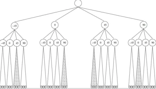
Enumerating all possible sequences consists in building an enumeration tree like in Figure 2. Each level of the tree represents a ply and each node has four children which are the four possible angle values of the next ply. The enumeration tree must have the number of plies +1 levels. A stacking sequence is a branch of the tree connecting the root to a leaf (the lowest node). One can see that the size of the tree grows exponentially with the number of plies and spanning the whole tree becomes quickly unfeasible.
The idea of the backtracking is to span the entire tree and to check at each node the admissibility of the partial stacking sequence constituted by the branch going from the root to the current node. If the partial sequence violates the constraint, then all the subtree derived from the current node is eliminated from the enumeration tree. This pruning technique reduces considerably the size of the tree and makes the enumeration efficient. For example in Figure \ref{tree2}, all the sub-sequences starting with (-45, 45), (0, 90), (45, -45) and (90, 0) are eliminated from the tree because they violate the 90° gap rule. The leaves of the tree are only the admissible sequences. The optimization algorithm is based on the backtracking procedure with a local search one. For more information, see [3].
Figure 2. Enumeration tree
5.
TEST CASE
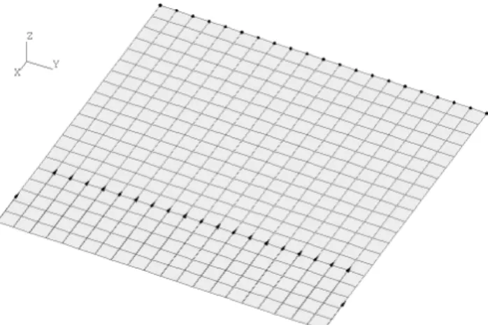
In this paper, the flat composite panel illustrated in Figure 3 is studied. The plate is clamped on one side, and submitted to compression on the other side. It is made of a laminate including 20 plies. Mindlin shell elements of the SAMCEF library are used [5]. The base material is C12K/R6376 Graphite/epoxy prepreg.
Figure 3. Finite element model, boundary conditions and loading of the test case
In the case of the continuous optimization with the gradient-based optimizer, three experiments where performed by considering different sets of design rules. The derivatives are computed by finite differences:
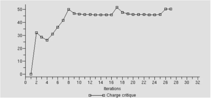
Test 1: design rules (R3, R4, R5). The optimal sequence found is [02/ -45/ 03/ 45/ 02/ 45]s and the
critical load is 50.15 with 27 evaluations (see Figure 4).
Test 2: design rules (R3, R5). The optimal sequence found is [010]s and the critical load is 59.28
with 4 evaluations (see Figure 5).
Test 3: design rule R3: same results as with test 2.
In the case of the discrete optimization with the backtracking procedure, three experiments where performed by considering different sets of rules:
Test 1: design rules (R3, R4, R5). The optimal sequence found is [03/ -45/ 03/ 45/ 0/ 45]s and the
critical load is 52.79 with 150 evaluations (see Figure 6).
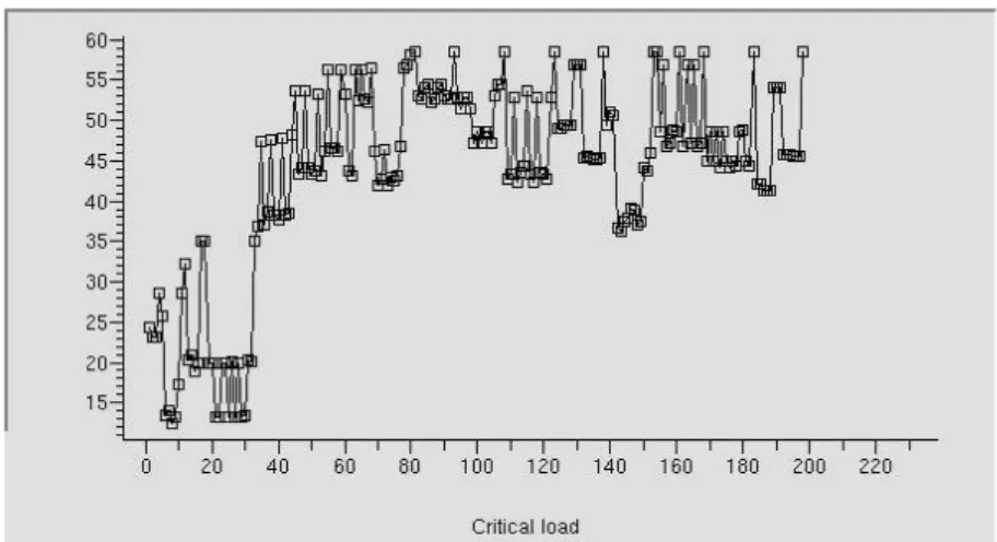
Test 2: design rules (R3, R5). The optimal sequence found is [07/ 45/ 0/ -45]s and the critical load
is 58.41 with 200 evaluations (see Figure 7). Test 3: design rule R3: same results as with test 2.
Figure 4. Test 1, rules (R3, R4, R5), the critical load with respect to the evaluation number. Continuous approach
Figure 5. Test 2, rules (R3, R5), the critical load with respect to the evaluation number. Continuous approach
Figure 6. Test 1, rules (R3, R4, R5), the critical load with respect to the evaluation number. Discrete approach
Figure 7. Test 2, rules (R3, R5), the critical load with respect to the evaluation number. Discrete approach
6.
CONCLUSIONS
In this paper, the optimal stacking sequence problem is solved. Specific design rules are taken into account in the optimization problem. Two numerical optimization approaches are compared, a pure discrete approach with a zero order algorithm, and a gradient-based approach with continuous design variables.
Only three design rules were taken into account in the problem: symmetry of the laminate, no more than 3 successive plies with the same angle, and the maximum gap between two adjacent (superposed) plies is 45°.
For the current version of the backtracking approach, we can’t work without the design rule R1. This explains why the [010)]s solution is not obtained for the tests 2 and 3, although this solution
is obtained with the continuous approach. For the problem including the three design rules R3, R4 and R5, the backtracking method provides a better solution. It is indeed well known that a gradient-based approach is attracted by local optimum.
The number of iterations needed to reach the solution is smaller when the gradient-based approach is used. However, the derivatives are computed with finite differences, which increases a lot the number of function evaluations.
Adaptation of the methods must be carried out in order to take into account the other design rules. The methods should also be tested on more complicated problems. Finally, an analytical sensitivity analysis should be derived for the gradient-based method to make it competitive to the backtracking approach.
7.
REFERENCES
2. Bruyneel M. (2011). SFP – A new parameterization for optimal material selection: application to conventional composite plies, Structural & Multidisciplinary Optimization, 43(1), pp. 17-27.
3. Zein et al. (2012). A primal-dual backtracking optimization method for blended composite structures. Structural & Multidisciplinary Optimization, 45, pp. 669-680.
4. Bruyneel M. et al. (2012). Stacking sequence optimization for constant stiffness laminates based on a continuous optimization approach. Structural & Multidisciplinary Optimization, 46, pp. 783-794.
5. SAMCEF: Système d’Analyse des Milieux Continus par Eléments Finis, SAMTECH S.A., Liège Science Park, Liège, Belgium.