Science Arts & Métiers (SAM)
is an open access repository that collects the work of Arts et Métiers Institute of Technology researchers and makes it freely available over the web where possible.
This is an author-deposited version published in: https://sam.ensam.eu
Handle ID: .http://hdl.handle.net/10985/8634
To cite this version :
Laurence FOUILLAND-PAILLE, Mohamed EL MANSORI - Experimental study of the
brittle–ductile transition in hot cutting of SG iron specimens - Journal of Materials Processing Technology - Vol. 213, n°2, p.201-213 - 2013
Any correspondence concerning this service should be sent to the repository Administrator : [email protected]
1
Experimental study of the brittle–ductile transition in hot cutting of SG iron
specimens
Laurence Fouilland a,*, Mohamed El Mansori a,b
aLaboratoire de Mécanique et Procédés de Fabrication - EA4106, Arts et Métiers ParisTech, Rue Saint Dominique,
BP508, 51006, Châlons en Champagne, France.
bMécaSurf – EA 4496, Arts et Métiers ParisTech, 2, Cours des Arts et Métiers - 13617 Aix en Provence cedex 1, France.
*
Corresponding author: Laurence FOUILLAND Tel.: +33 3 26 69 91 21; Fax: +33 3 26 69 91 97 E-mail address: [email protected]
ABSTRACT
The present paper investigates the brittle-ductile transition (BDT) of the primary shear zone during cutting of spheroidal graphite (SG) iron in the austenitization temperature range (around 1000 °C). The experimental tests were performed using a cutting test bench in the cutting speed range of 0.8 to 1.6m.s-1. The cut surfaces were studied using optical microscopy
and Scanning Electron Microscope (SEM) analysis techniques. The obtained results revealed either consequent deep fractured regions governed by a brittle-cracking regime (BCR) or a crack-free cut surface governed by a ductile-shear regime (DSR) with large plastic deformations.
When cutting data were discussed with respect to the influences of cutting parameters and obtained cut surface, the correlation is significantly rich. Both cut surface integrity, cutting force curves and metallographic results show a BDT indicating a change in the dominating hot cutting process mechanism. Such a transition is associated with the dynamic recrystallization promoting strain softening andhot cutting by ductile shearing.
Keywords Hot cutting; SG iron; Brittle-ductile transition; Dynamic recrystallization; Surface damaging
1. INTRODUCTION
Cutting with shear localization involves thermo-plastic instability in the primary shear zone. Indeed, Barry et al. (2001) showed that in the machining of titanium and its alloys, cleavage is the mechanism
2 of catastrophic failure in the chips produced at low cutting speeds within the upper primary shear zone. Barry and Byrne (2002) showed that the machining of hardened steel involves the same phenomena. However, the underside of saw-tooth segments produced at relatively higher cutting speed exhibits evidence of ductile fracture related to a noticeable thermal softening within the primary shear zone.
This transition from brittle to ductile behavior was already addressed by Recht since 1964 as a catastrophic shear that occurs when the thermal softening rate exceeds the strain hardening (Recht, 1964).
Wu et al. (1993) demonstrated that such a brittle-ductile transition (BDT) also concerns the machining of brittle materials like silicon single crystal. When the ductile mode is activated, the BDT ensures high surface integrity, nearly the same as the one of a polished surface, with appreciable low values of surface roughness (Ra parameter).
Yan et al. (2002) showed that a negative rake angle and/or an extremely small chip thickness (h) of the same order of cutting edge radius provides, in front of the cutting edge, a stress state similar to the hydrostatic stress field which in turn is the prerequisite for ductile regime of brittle materials.
For metallic engineering alloys, the BDT is based on important restoration phenomena such as dynamic recovery and dynamic recrystallization.
Due to the great impact of dynamic recrystallization on the microstructure and the mechanical properties in industrial hot deformation processing such as forging, many authors examine the hot working behavior of different materials. Concerning the austenitic stainless under hot compression tests (Mirzadeh and Najafizadeh, 2010) or hot torsion tests (Ryan and McQueen, 1990) at temperatures of 900-1200°C with strain rate of 0.001-10 s-1, the kinetic of dynamic recovery in austenite phase is deemed low. The authors also show that the most often dynamic recrystallization is activated at a critical condition of stress accumulation. By increasing the strain rate up to 10 s-1, the
samples deformed at 1000°C do not point anymore the typical dynamic recrystallization microstructure observed with the strain rate of 0.1 s-1.
3 In the SG iron family more especially related to the present study, authors like Dragan et al. (1969) and Dragos et al. (1978) have studied the dynamic recrystallization of these SG irons. Using hot torsion tests, they have shown the influence of temperature (650-1050°C) and strain rate (0.8-3.1s-1)
on SG hot deformability. The stress-strain behavior they obtained can be subdivided into three successive domains: the strain hardening one, which occurs for low strains and at the end the steady-state regime for high strains. The two above domains being separated by a transition domain where dynamic recrystallization takes place with a consecutive strain-softening. According to the authors, such dynamic recrystallization appears when SG iron is solicited at relatively high strain rates in the austenite phase. Since initiation of the dynamic recrystallization depends on both temperature and strain rate, an increase in the strain rate leads to an increase in the stress threshold of dynamic recrystallization onset. In other terms, Dragos speaks of “a delayed activation” in the occurrence of the recrystallized microstructure (Dragos et al., 1978).
Recently, the SG iron treated ADI (Austempered Ductile Iron) has been developed to provide an excellent combination of strength, fracture toughness and wear resistance at low cost. Thus, the “green” ADI grade is produced by a novel manufacturing technology known as continuous casting-heat treatment to save energy and time in foundry (Meena and El Mansori, 2012). Because of its high yield strength to weight ratio and enhanced mechanical properties, ADI replaces the forged steel and cast iron components used in the transportation industry with these light weight substitutes (Meena and El Mansori, 2011).
ADI products offer a wide range of properties according to their heat treatment parameters and the combined effect of austempering and deformation of prior austenite. For example, the fracture behavior of ADI with variations in austempered microstructures was studied by Batra (2005). Achary and Venugopalan (2000) investigated a thermo-mechanical method for processing ADI microstructure by the grain refinement of parent austenite during deformation in the austenitizing temperature range, before the austempering treatment. Thus, Achary (2000) found that tensile strength, yield strength and elongation values increase with increasing austenite deformation up to 40%.
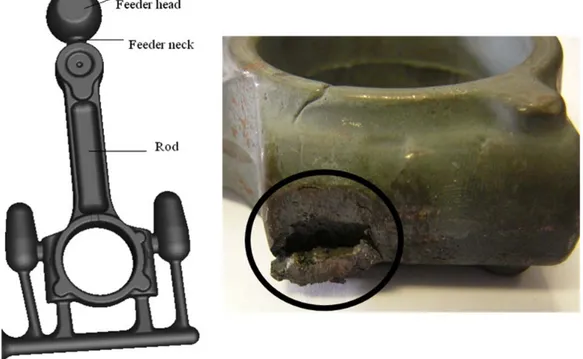
4 Based on these principles, ADI rods are manufactured by a combined casting and forging process (Fouilland and El Mansori, 2010) followed by an austempered heat treatment. However, a major concern when using this advanced processing technology of ADI production is the deep cracking damage (figure 1) introduced in ADI rods during the hot spruing operation.
Figure 1. Cast rod before and after the hot spruing operation which causes a well-seen deep cracking damage (surrounded zone).
The spruing operation consists in freeing the rod from its feeder heads by shearing the feeder neck zone under a blanking process. In the mass production context and to keep competitive manufacturing costs, spruing is performed at about 1000°C, just after the casting operation without any cooling between casting and forging. At this temperature, SG iron is in the range of stability of the austenite phase. According to previous studies (Mirzadeh and Najafizadeh, 2010) and due to the low stacking fault energy of austenite, the major restoration process during hot deformation is dynamic recrystallization. In fact, the low stacking fault of the face centered cubic structure such as the austenite promotes most of the lattice dislocations to dissociate into partials. This in turn, severely restricts dislocation cross-slip and dynamic recovery which can balance work hardening. The kinetics of dynamic recovery is low and the dynamic recrystallization can rather initiate.
5 Dynamic recrystallization is hence an important phenomenon that controls mechanical properties of products obtained by hot working process. Nevertheless, the open literature does not report any fact concerning the induced damage of SG Iron during hot cutting between 900 and 1000°C. Thus, it is important to design a thermo-mechanical test able to reproduce the loading conditions involved during the hot spruing operation: cut by plastic shearing in planar fashion (Fouilland and El Mansori, 2010).
As an effort to better understand this, the present study deals, firstly, with the way of experimentally avoid deep cracking damage during hot cutting of SG iron. Then, the cutting conditions to ensure the BDT during the hot cutting process are discussed in relation with chip formation mechanisms. Finally, the presence or absence of the dynamic recrystallization within the primary shear zone is particularly focused.
2. EXPERIMENTAL PROCEDURES
To reproduce the mechanical conditions of the spruing operation on cast parts, a hot cutting test bench has been devised. This allows studying the shearing action in low cutting speed range. The SG cast specimens hold a chemical composition given in Table 1.
Element C Si Mn S Cu Ni Cr Mo Mg
Composition (wt %) 3.35 2.72 0.16 0.009 0.87 0.71 <0.03 0.21 0.043
Table 1. Chemical composition of SG cast specimens
The SG iron specimens consist in machined cast blocks with a pin element of a diameter and a height h which is entitled to reproduce a partly feeder neck (figure 2a).
6 Figure 2. Hot cutting test arrangement:
(a) SG iron specimen with a pin element of a diameter and a height h.
(b) The work-specimen clamped in the planning machine while the HSS tool moves against the pin element in the cutting direction.
The dimension h is of the same order of magnitude as a typical depth of cut while the dimension is made correspond to a representative shear plane length. The specimens are austenitized at 1000°C for ten minutes before the hot cutting process. The clamped specimen into a planning machine and the tool is shown in Fig. 2b. The clamping setup has been manufactured such as two pneumatic cylinders allow a rapid clamping of the specimen, and a bed of refractory inserts
7 prevents heat losses. Indeed, the SG iron specimen must stay in the (austenitization temperature range) range of stability of the austenite phase during the cutting operation (i.e. between 980 and 1000°C). To evaluate the “available time” to perform the test with this condition fulfilled, thermocouples embedded in cutting specimens (Figure 3(a)) have been used to measure the loss of temperature between the take-out of specimen from the furnace and the beginning of the cutting test. Figure 3(b) shows the temperature decrease with time. According to this curve (Fig. 3b), the elapsed time must not exceed seven seconds. Consequently, the experimental tests have been systematically performed under the required conditions.
Figure 3. (a) Temperature measurement obtained thanks to an embedded thermocouple; (b) Temperature variation in a heated specimen during cooling into the clamping setup.
8 The orthogonal cutting tests has been performed at three different cutting speeds (0.8m.s-1, 1.3m.s-1
and 1.6 m.s-1) with three various rake angles (+10°; 0° and -10°) using high speed steel (HSS) tools
(flank angle = 6°). The cutting tools geometry is detailed in Table 2. The choice of such experimental variables has been guided by the processing conditions of SG iron rods and limited by the test bench capabilities. Moreover, three various heights h of the pin element (5 mm, 10 mm and 15 mm) and three diameters (5 mm, 7.5mm and 10mm) have been tested.
Table 2. Cutting tools geometry.
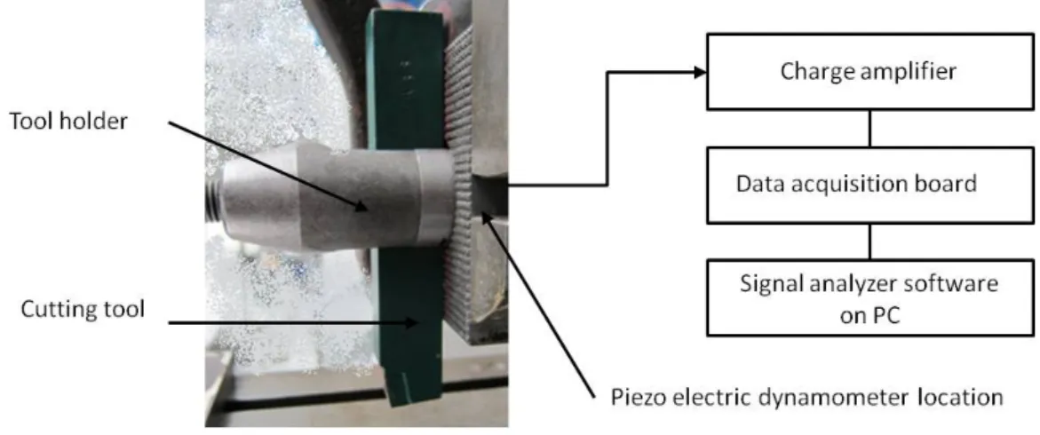
The cutting force in the cutting direction has been measured using a KISTLER piezoelectric dynamometer (type 9104A) mounted on the tool holder (Fig. 4). By the piezoelectric technology, when subjected to a cutting load, quartz produces an electrical charge proportional to the load.
9 In order to evaluate the various involved physical phenomena taking place during the hot cutting tests, a high speed camera (PHOTRON FASTCAM SA5) has been used to provide video recordings of the cutting operation. The pictures of the cutting test have been recorded at a frequency of 15,000 frames per second with a resolution of 768 x 648 pixels. For each cutting condition, the cut surfaces (specimen cut surface and pin cut surface) specified in Figure 5 have been analyzed using optical microscope and scanning electron microscope (SEM) techniques.
Figure 5. Photograph of the machined specimen showing the cut surface of both the base specimen and the pin element.
3. RESULTS AND DISCUSSION
3.1 Optical observation of cut surfaces
Figure 6(a) shows optical micrographs of the cut surface of the specimen (h= 15mm and =10mm) for different cutting conditions. At low cutting speeds (≤ 1.3m.s-1) irrespective of the tool rake angle,
pin elements are completely and nearly perfectly cut, showing a whole quasi flat cut area (referred to as AC). For the highest cutting speed (=1.6 m.s-1) and the rake angles of -10° or 0° (tests respectively
named as 1.6 m.s-1_-10° and 1.6m.s-1_0°) the aspect of the cut surface becomes heterogeneous: a fractured area (referred to as AF) showing deep cracking (typical depth of a few millimeters)
10 Figure 6. Optical views of specimen cut faces after hot cutting tests versus to the rake angles of the HSS tool and the cutting speeds tested (h=15mm;=10mm). (a) Cut and Fractured areas are respectively named AC and AF. (b) Typical
cross section view highlighting deep cracking in AF.
Two distinct trends can be identified from the first set of tests:
The fracture propensity increases with the decrease of the rake angle; The fracture propensity increases with the increase of the cutting speed. (a)
11 Clearly here, cutting parameters, which are the most influencing (in terms of presence and span of the fractured area in the cut surface) are those with a negative rake angle (-10°) associated with the highest cutting speed (1.6 m.s-1). Consequently, all other pin diameters (5 mm, 7.5 mm and 10 mm)
and pin heights (5 mm, 10 mm and 15 mm) have been tested under this cutting condition (1.6 m.s-1 and -10°) to investigate the influence of dimensional characteristics on the cutting surface morphology.
Corresponding specimens cut surfaces are shown in figure 7 for different dimensional conditions. The fractured area (AF) occurs only for the specimen with a pin height of 15mm and a pin diameter of
10mm (as identified above Fig. 6, specimen named 1.6 m.s-1_-10°).
Figure 7. Optical views of specimen cut faces after hot cutting tests (Cutting speed=1.6m.s-1; tool rake angle =-10°) versus to the pin heights and diameters tested. Cut and Fractured areas are respectively named AC and AF.
12 Finally, one can observe that the generation of a damaged cut surface is only activated by the combinations of several penalizing parameters: negative (or null) rake angle of the tool; cutting speed ≥ 1.6m.s-1; ≥10 mm; h ≥ 15 mm.
3.2 SEM observation of cut surfaces
In order to understand the physical mechanisms involved in the generation of both Ac and AF regions,
SEM observations have been made. They can be seen on figures 8 and 9. The AC region shows a
flat cut surface without any deep damage. On the contrary, the AF area shows a brittle fracture which
results from micro-cracks associated with the graphite-matrix interface that surround the spherical nodules and then propagate to the matrix.
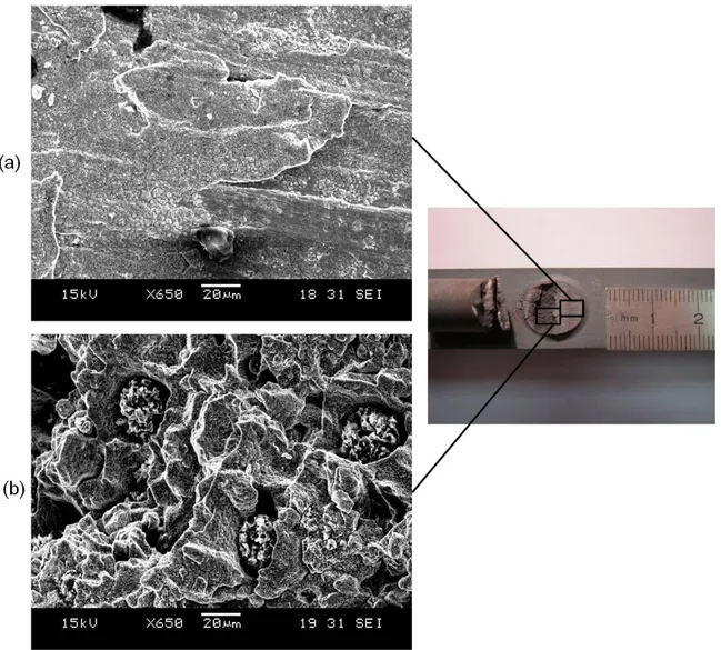
Figure 8. SEM details views of the 1.6 m.s-1 _-10° specimen cut face in (a) the cut area (AC) ; (b) the fractured area (AF).
13 Cross section micrographic views of the same specimen (1.6 m.s-1 _-10°) are shown on figure 9 (a)
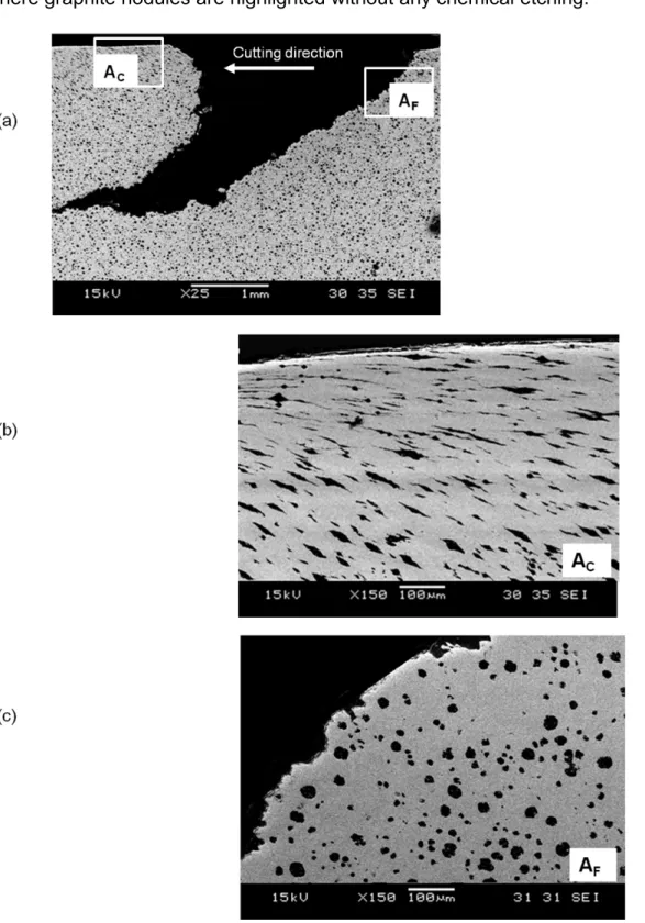
where graphite nodules are highlighted without any chemical etching.
Figure 9. Cross section SEM view of 1.6m.s-1_-10° specimen with deep cracking damage (8(a)). Microscructural details of the AC area (8(b)) and the AF area (8(c)). [Cutting speed = 1.6 m.s-1; rake angle = -10°; h=15mm and =10mm].
In the AC zone (figure 9(b)), highly elongated graphite nodules parallel to the cutting direction are
14 nodules shape (figure 9(c)). This suggests a brittle fracture in AF whereas AC shows a large plastic
deformation of the nodules consistent with a ductile shear mode.
3.3 SEM observation of “chip-pin” faces
The analysis of the “Chip-Pin” face corresponding to the AF cut surface is illustrated in figure 10. A
decohesive rupture surface can be observed where the graphite nodules interface acts as crack initiation sites.
Figure 10. SEM views of 1.6m.s-1_-10° specimen “Chip–Pin” cut face. [Cutting speed = 1.6 m.s-1; rake angle = -10°;
h=15mm and =10mm].
For comparison, a “Chip-Pin” cut without any deep damage (1.3m.s-1_-10° specimen for example)
has been observed. It indeed shows a cut surface oriented in the direction of maximum shear stress (cutting direction) with elongated dimples showing cup-cone ductile fracture pattern (figure 11).
15 Figure 11. SEM views of 1.3m.s-1_-10° specimen “Chip–Pin” cut face. [Cutting speed = 1.3 m.s-1; rake angle = -10°; h =15mm and =10mm].
After these tests and observations, a first set of recommendations can be made concerning the process parameters to choose in order to avoid deep cracking damages during the spruing operation: Negative rake angle for the cutting tool should be avoided. As it will be shown in the figure 13
(pictures recorded by the high speed camera), a negative tool rake angle induces bending of the pin element that favors plowing rather than cutting with a brittle fracture and a deep damaging if the cutting speed is high enough (≥ 1.6m.s-1). Avoiding negative rake angle allows soliciting the pin in pure shear with an undamaged cut surface.
The cutting speed should be inferior to 1.6m.s-1: the influence of this parameter will be discussed more specifically in the remaining sections of this paper.
The pin geometry should be such as h <15mm and <10mm.
To confirm these recommendations and, more especially, to understand the specific role of the cutting speed in the damaging process, the recorded force curves and video recordings of the tests are examined in the next section.
16 3.4 Hot cutting force curves and video recordings
The cutting force curves versus the tool displacement are shown in figure 12 for the tests made on both previous compared specimens (1.3m.s-1_-10° and 1.6m.s-1_-10° ones).
Figure 12. Experimental cutting force-displacement curves for both 1.3 m.s-1_-10° and 1.6m.s-1_-10° specimens. [h =15mm and =10mm].
The reported results (Fig. 12), representative for a large number of similar tests, state the following specific information:
The “Chip-pin” element is removed from the specimen after a short tool displacement d (≤ 0.5
);
The curve recorded for a specimen presenting a large fractured area (1.6m.s-1_-10° specimen)
reaches a peak of a maximum value before coming down smoothly to zero;
The curve obtained for a specimen without any fractured area (1.3m.s-1_-10° specimen) reaches a plateau for a course of several millimeters (≈ 0.3) before falling down quickly to zero. The curve then shows some rebounds.
0 5 10 15 0 5 10 Cutting force (kN) Tool displacement (mm) 1.3 m.s‐1_‐10° specimen 1.6 m.s‐1_‐10° specimen
17 The dependence between the falling portion of the force-displacement curve and the presence or absence of the fractured area within the specimen cut surface may be explained by the brittle-ductile transition (BDT) taking place within the SG iron specimen at the hot temperatures.
In order to confirm this assertion, all the cutting force data have been confronted to the pictures recorded during the test by the high speed camera.
On figures 13 and 14 the corresponding views of hot cutting force data are respectively shown for the both 1.3 m.s-1_ -10° and 1.6m.s-1_-10° specimens.
In both cases, the negative rake angle provides the pin bending and a severe strain localization at its base (scenes of both figures 13 (b) and 14 (b)), under the tool motion against the pin element. According to Grzesik (2008), the compressive zone in the workpiece subsurface expands visibly with negative rake angles. As a consequence, material is downward suppressed and the compressive stress components become predominant. This provides a stress state similar to the hydrostatic stress field with a more intensive work-hardening than for cutting tools with positive rake angles.
For the lowest cutting speed (1.3 m.s-1_ -10° specimen) a named Ductile-Shear Regime (DSR)
governed by plastic deformation seems established: the shear stress on the shear plane increases as the tool is fed, until a sufficient value is reached to suddenly produce the fracture. Between the scenes and of figure 13 (b), the pin element is completely removed and ejected following a flat surface free of cracks. A schematic view of this phenomenon is illustrated on the figure 13 (c).
18 Figure 13. Views of hot cutting action for the 1.3m.s-1_-10° specimen (b) with corresponding cutting force data (a).
Schematic view of the ductile-shear regime (DSR) governed by the plastic deformation occurring at the base of the “chip pin” element (c). [Cutting speed = 1.3m.s-1; rake angle = -10°;h =15mm and =10mm].
As the cutting speed increases to 1.6 m/s (1.6m.s-1_-10° specimen), the pin element is rather
extruded between the tool and the specimen free surface (figure 14). During this extrusion, the “Chip-pin” element does not slide along the tool face but is rather pushed down. A named Brittle-Cracking
19 Regime (BCR) governed by the brittle deformation mode is rather established: an initial crack is formed within the pin base in the vicinity of the cutting edge where high tensile normal stresses take place. The fracture occurs with consequent surface and subsurface brittle damages before a short shearing process starts (see schematic view in figure 14(c)). In such a combination of a high cutting speed (a high implied strain rate) and an hydrostatic pressure field caused by negative rake angle, the energy required to propagate cracks is believed to be lower than the energy required for plastic deformation, so that brittle-cracking regime is the predominant mechanism of the material removal.
20 Figure 14. Views of hot cutting action for the 1.6 m.s-1_-10° specimen (b) with corresponding cutting force data (a).
Schematic view of the brittle-cracking regime (BCR) governed by the brittle deformation of the “chip pin” element (c). [Cutting speed = 1.6 m.s-1; rake angle = -10°; h =15mm and =10mm].
21 3.5 Hot cutting stages
From the video recordings, different cutting stages can be identified on the cutting force curves. For the ductile-shear regime (DSR) they are brought out in figure 15:
Figure 15. Typical cutting force-displacement curve for ductile-shear regime. [1.3 m.s-1 _-10° specimen i.e. Cutting speed = 1.3 m.s-1; rake angle = -10°; h =15mm and =10mm].
Stage corresponds to an elastic behavior of the material under the tool solicitation; Stage corresponds to the material plastic deformation by ductile shear. The cutting
force rises to a plateau for a more or less short tool displacement according to the cutting speed tested (Fouilland and El Mansori, 2010);
At the stage , the “Chip-pin” is broken free from the specimen along a shear plan. The cutting force falls suddenly to zero;
Stage reveals the shaping of the remaining excess metal with small thickness.
On the contrary, typical stages of the brittle-cracking regime (BCR) are shown in figure 16. After stage (elastic behavior), a short crack stage takes place (stage ) followed by simultaneous “Chip-pin” ejection and shaping of the remaining excess thickness (Stage ).
22 Figure 16. Typical cutting force-displacement curve for brittle-cracking regime. [1.6 m.s-1 _-10° specimen i.e. Cutting speed = 1.6 m.s-1; rake angle = -10°; h =15mm and =10mm].
The existence of a fractured area within the cut surface is now directly related to the brittle behavior (BCR) without any plastic deformation stage identified from the force-displacement curve. On the contrary, a crack-free cut surface is associated to the ductile regime (DSR) with a large ductile deformation stage by shear (stage on figure 15).
However, a question arises here: how this BDT can be connected with the dynamic recrystallization phenomenon, which is able to significantly refine austenite grains, enhance ductility and allow the material to endure large shear deformations without deep cracks.
3.6 Dynamic recrystallization microstructure
The study of dynamic recrystallization by metallography has been extensively reported in the literature and more recently by Achary and Venugopalan (2000) and Mirzadeh and Najafizadeh (2010).
To perform this analysis, one has to be aware of the constraint that makes the metallographic analysis questionable: phase change occurs during the cooling of the specimen from the experimental temperature of the hot cutting process. This means that the observed matrix microstructure is not the same as the one “seen” by the tool during the test. Nevertheless, this kind of
23 study can, however, reveal some interesting information as long as these phase changes are taken into account. Especially, to ensure a certain relevancy of this kind of analysis, an oil quenching is performed to “freeze” the size of the austenite grains (that are transformed into martensite needles). Accordingly, in this study, an oil quenching has been performed just after the hot cutting test on 1.3 m.s-1_-10° and 1.6 m.s-1_-10° specimens to prepare this metallographic analysis. The obtained
martensitic structures of specimens are shown on figure 17.
Figure 17. Cross section microstructural details after oil quenching.
(a) sub cut-surface of the 1.3m.s-1 _-10° specimen, (b) far away from the cut surface of the 1.3m.s-1 _-10° specimen, (c) 1.6 m.s-1 _-10° specimen just below (AF) region. [Etched with supersaturated nitric acid].
The observed cross sectional surface of the 1.3 m.s-1_-10° specimen shows that martensite needles
just below the cut surface are finer (figure 17-a) and shorter than these observed far away from the cut surface (figure 17-b). Concerning the 1.6 m.s-1_-10° specimen cut surface (i.e. just below the
24 fractured region (AF)), no needles refinement was found (figure 17-c). According to Dragos et al.
(1978), and as mentioned above, the fineness of the needles depends on the austenite grains size from which they originate and is thus a valid indicator of the dynamic recrystallization activation. This allows asserting that the dynamic recrystallization phenomenon is activated at the vicinity of the cut surface only for the1.3 m.s-1_-10° specimen. For the 1.6 m.s-1_-10° specimen the cutting speed
seems high enough to prevent this phenomenon. As a consequence, this metallographic study gives confidence in the previous results and indicates that the dynamic recrystallization is the main origin of the BDT in SG hot cutting process.
3.7 Chip-pin formation mechanisms and BDT
The chip-pin formation mechanisms in the primary shear zone may be explained regarding the well-known underlying chip formation mechanisms and material deformation behavior. Concerning machining with a flat-faced tool, Grzesik (2008) explains the formation of usually called discontinuous and shear-types chips using the appropriate stress/strain curve as follows (figure 18):
Figure 18. Chip formation mechanisms in terms of stress/strain curves [Grzesik (2008)].
Discontinuous chips are formed when machining brittle materials or materials containing point of stress concentration. Fracture occurs when material undergoes only elastic deformation (curve 4) and a crack propagates from the cutting edge to the free surface. When materials have sufficient
25 ductility, the formation of a continuous or a segmented (also called saw-tooth) chip takes place, which generally results in a good surface finish. Continuous chips are related to curve 1 with large plastic flow of the material and characteristic neck of a tensile specimen developed after the critical value of shear strain SO. If the plastic flow is not so intensive and shear strain exceeds slightly SO,
the onset of chip segmentation is observed (partially segmented chip vs curve 2). During rapid plastic deformation (as speed increases), the chip segmentation starts to develop until complete separation (elemental chip vs curve 3). In this case, the material necks before fracture but at relatively lower shear stress. It should be noted that all three latter types of chips are formed by shearing mechanisms and are related to the plastic deformation of ductile work materials.
The root cause of segmented chip formation is a catastrophic thermo-plastic instability localized in the adiabatic shear region. In this region of intensive shear, the decrease in flow stress due to thermal softening resulting from the local increase in temperature is more pronounced than the associated strain-hardening.
In the present study, when the strain softening resulting from dynamic recrystallization is more pronounced than the associated strain-hardening, a ductile shear regime (DSR) takes place (figure 19 vs curve DSR) and the pin element is completely sheared (ductile sheared chip-pin in figure 19) following a flat shear surface in analogy with the segmented chip formation mechanism. The discontinuous chip formation mechanism described by Grzesik (2008) may also aid the brittle cracked chip-pin mechanism comprehension (figure 19 vs curve BCR) when the pin fracture occurs without any plastic deformation.
26 Figure 19. Chip-pin formation mechanisms in terms of stress/strain curves (BCR=Brittle Cracking Regime, DSR=Ductile Shear Regime).
To facilitate easier rationalization of the present study results, Table 3 gives strain hardening and strain softening (resulting from dynamic recrystallization) trends with the rake angle or the cutting speed increase. The both last columns in Table 3 indicate respectively whether the DSR or the BCR is activated for the chip-pin formation with the lower values tested (rake angle= -10° or cutting speed = 0.8 m.s-1), and the expected transition for the higher values tested. Such trends do not predict the
behavior of the SG pin in hot cutting but aid the explanations of the chip-pin formation mechanisms. Trends concerning the pin height (h) or the pin diameter () do not appear in Table 3 because they are not yet well understood.
27 Table 3. Strain hardening and strain softening trend with the increase of the rake angle or the cutting speed (= increase, =decrease, = transition, BCR= Brittle Cracking Regime, DSR= Ductile Shear Regime).
4. CONCLUSIONS
This experimental study using a shearing test bench has allowed to understand the brittle-ductile transition (BDT) taking place within the primary shear zone under an orthogonal cutting process at low cutting speeds (0.8 to 1.6m.s-1) and high temperatures (980 to 1000°C). The experimental hot
cutting tests, entitled to reproduce the spruing operation on cast SG iron parts, have revealed that the deep cracks of the cut surfaces are related to a brittle behavior (BCR) of the material that is activated by a combination of cutting parameters (negative rake angle, high cutting speed) promoting strain hardening rather than strain softening.
In contrast, when strain softening is more pronounced than the associated strain-hardening, the energy required to propagate cracks is larger than that required for plastic deformation by shearing. A ductile shear regime (DSR) thereby takes place.
The metallographic results obtained on oil quenched specimens support the idea that such a BDT is associated with the dynamic recrystallization initiated in austenite SG phase. The dynamic recrystallization promotes strain softening and hence reduces the material resistance which leads to hot cutting by ductile-shear mode (DSR) leaving a crack-free cut surface.
ACKNOWLEDGMENTS
The authors would like to express their sincere thanks to J. VOISIN (Assistant Engineer at the LMPF Research Group) for his valuable technical support all along this work. They would also like to thank Dr R. MOULART (Assistant Professor at the LMPF) for helpful discussions and his assistance in the preparation of the manuscript.
28
REFERENCES
Achary J., 2000. Tensile properties of austempered ductile iron under thermomechanical treatment, Journal of Materials Engineering and Performance, 9, pp. 56-61.
Achary J., Venugopalan D., 2000. Microstructural development and austempering kinetics of ductile iron during thermomechanical processing, Metallurgical and Materials Transactions A, 31A, pp. 2575-2585.
Barry J., Byrne G., Lennon D., 2001. Observations on chip formation and acoustic emission in machining Ti-6Al-4V alloy, International Journal of Machine Tool & manufacture, 41, pp. 1055-1070.
Barry J., Byrne G., 2002. The mechanisms of chip formation in machined hardened steels, Journal of Manufacturing Science and Engineering, 124, pp. 528-535.
Batra U., 2005. Fracture behavior and mechanism in austempered ductile iron, Journal of Failure Analysis and Prevention, 5, pp. 75-81.
Dragan I., Vermesan G., Dragos E., 1969. Déformation à chaud des fontes; son influence sur leurs propriétés mécaniques et structurales, Fonderie, 284, pp. 453-464 (in french).
Dragos E., Zubac V., Zirbo G., 1978. Etude sur les fontes à graphite nodulaire pour l’estampage à chaud. Hommes et fonderie, pp.37-42 (in french).
Fouilland L., El Mansori M., 2010. Hot Cutting of real-time cast-forged SG ductile iron for automotive rods. AIP Conference Proceedings, 1315, pp. 1193-1198.
29 Grzesik W., 2008. Advanced machining processes of metallic materials, theory modeling and applications. Elsevier. Chapters 6 and 7.
Meena A., El Mansori M., 2011. Study of dry and minimum quantity lubrification drilling of novel autempered ductile iron (ADI) for automotive applications, Wear 271, pp. 2412-2416.
Meena A., El Mansori M., 2012. Drilling performance of green austempered ductile iron (ADI) grade produced by novel manufacturing technology. International Journal of Advanced Manufacturing Technology, 59, pp. 9-19.
Mirzadeh H., Najafizadeh A., 2010. Prediction of critical conditions for initiation of dynamic recrystallization, Materials and design, 31, pp. 1174-1179.
Recht R. F., 1964. Catastrophic thermoplastic shear, Journal of Applied Mechanics, pp. 189-193.
Ryan N.D., McQueen H.J., 1990. Flow stress, dynamic restoration, strain hardening and ductility in hot working of 316 steel, Journal of Materials Processing Technology, 21, pp. 177-199.
Wu T.C., Morita N., Yoshiba Y., 1993. Study on the diamond cutting of silicon single crystal (1st report, the effect of brittle-ductile transition on surface integrity, Transaction of the Japan Society of Mechanical Engineers, Part C, 59, pp. 283-288.
Yan J., Syoji K., Kuriyagawa T., Suzuki H., 2002. Ductile regime turning at large tool feed, Journal of Material Processing Technology, 121, pp. 363-372.
30 List of tables
Table 1. Chemical composition of SG cast specimens Table 2. Cutting tools geometry.
Table 3. Strain hardening and strain softening trend with the increase of the rake angle or the cutting speed (= increase, =decrease, = transition, BCR= Brittle Cracking Regime, DSR= Ductile Shear Regime).
31 List of figures
Figure 1. Cast rod before and after the hot spruing operation which causes a well-seen deep cracking damage (surrounded zone).
Figure 2. Hot cutting test arrangement:
(a) SG iron specimen with a pin element of diameter and h height.
(b) The work-specimen clamped in the planning machine while the HSS tool moves against the pin element in the cutting direction.
Figure 3. (a) Temperature measurement obtained thanks to an embedded thermocouple; (b) Temperature variation in a heated specimen during cooling into the clamping setup.
Figure 4. Description of the force sensor setup.
Figure 5. Photograph of the machined specimen showing the cut surface of both the base specimen and the pin element.
Figure 6. Optical views of specimen cut faces after hot cutting tests versus to the rake angles of the HSS tool and the cutting speeds tested (h=15mm; =10mm). (a) Cut and Fractured areas are respectively named AC and AF. (b) Typical cross section view highlighting deep
cracking in AF.
Figure 7. Optical views of specimen cut faces after hot cutting tests (Cutting speed=1.6m.s-1;
tool rake angle = -10°) versus to the pin heights and diameters tested. Cut and Fractured areas are respectively named AC and AF.
32 Figure 8. SEM details views of the 1.6 m.s-1 _-10° specimen cut face in (a) the cut area (A
C) ;
(b) the fractured area (AF). [Cutting speed = 1.6 m.s-1; rake angle = -10°; h=15mm and =10mm].
Figure 9. Cross section SEM view of 1.6m.s-1_-10° specimen with deep cracking damage
(8(a)). Microscructural details of the AC area (8(b)) and the AF area (8(c)). [Cutting speed = 1.6
m.s-1; rake angle = -10°; h=15mm and =10mm].
Figure 10. SEM views of 1.6m.s-1_-10° specimen “Chip–Pin” cut face. [Cutting speed = 1.6
m.s-1; rake angle = -10°; h=15mm and =10mm].
Figure 11. SEM views of 1.3m.s-1_-10° specimen “Chip–Pin” cut face. [Cutting speed = 1.3
m.s-1; rake angle = -10°; h =15mm and =10mm].
Figure 12. Experimental cutting force-displacement curves for both 1.3 m.s-1_-10° and 1.6m.s -1_-10° specimens. [h =15mm and =10mm].
Figure 13. Views of hot cutting action for the 1.3m.s-1 _-10° specimen (b) with corresponding
cutting force data (a). Schematic view of the ductile-shear regime (DSR) governed by the plastic deformation occurring at the base of the “chip pin” element (c). [Cutting speed = 1.3m.s
-1; rake angle = -10°; h =15mm and =10mm].
Figure 14. Views of hot cutting action for the 1.6 m.s-1 _-10° specimen (b) with corresponding
cutting force data (a). Schematic view of the brittle-cracking regime (BCR) governed by the brittle deformation of the “chip pin” element (c). [Cutting speed = 1.6 m.s-1; rake angle = -10°; h =15mm and =10mm].
33 Figure 15. Typical cutting force-displacement curve for ductile-shear regime. [1.3 m.s-1 _-10°
specimen i.e. Cutting speed = 1.3 m.s-1; rake angle = -10°; h =15mm and =10mm].
Figure 16. Typical cutting force-displacement curve for brittle-cracking regime. [1.6 m.s-1 _10°
specimen i.e. Cutting speed = 1.6 m.s-1; rake angle = -10°; h =15mm and =10mm].
Figure 17. Cross section microstructural details after oil quenching. (a) sub cut-surface of the 1.3m.s-1 _-10° specimen, (b) far away from the cut surface of the 1.3m.s-1 _-10° specimen, (c) 1.6 m.s-1 _-10° specimen just below (AF) region. [Etched with supersaturated picric acid].
Figure 18. Chip formation mechanisms in terms of stress/strain curves [Grzesik (2008)].
Figure 19. Chip-pin formation mechanisms in terms of stress/strain curves (BCR=Brittle Cracking Regime, DSR=Ductile Shear Regime).