Science Arts & Métiers (SAM)
is an open access repository that collects the work of Arts et Métiers Institute of
Technology researchers and makes it freely available over the web where possible.
This is an author-deposited version published in: https://sam.ensam.eu
Handle ID: .http://hdl.handle.net/10985/18355
To cite this version :
G. BIDRON, Anis DOGHRI, Thierry MALOT, Florent FOURNIER-DIT-CHABERT, Marc THOMAS,
Patrice PEYRE - Reduction of the hot cracking sensitivity of CM-247LC superalloy processed by
laser cladding using induction preheating - Journal of Materials Processing Technology - Vol. 277,
p.1-9 - 2020
Any correspondence concerning this service should be sent to the repository
Administrator : archiveouverte@ensam.eu
Reduction of the hot cracking sensitivity of CM-247LC superalloy processed
by laser cladding using induction preheating
G. Bidron
a,d, A. Doghri
b,c, T. Malot
a, F. Fournier-dit-Chabert
b, M. Thomas
b, P. Peyre
a,⁎
aLaboratoire PIMM, UMR 8006 CNRS - Arts et Métiers ParisTech– CNAM, 151 Bd de l’Hôpital, 75013, Paris, France bONERA - The French Aerospace Lab., 29 Avenue de la Division Leclerc, 92322, Chatillon Cedex, France
cUniversité de Lorraine, CNRS, Arts et Métiers ParisTech, LEM3, F-57000, Metz, France dAPS Coatings, Z.I. de Noisiel Rue de la Mare Blanche F-77448 Marne-la-Vallée Cedex 02, France
Associate Editor: A Clare Keywords: Cladding Laser CM-247LC Preheating A B S T R A C T
In the present work, the repair of CM-247LC superalloy has been investigated by using a laser cladding process. Since this material is well known for its high hot-cracking susceptibility in Heat Affected Zone during welding, repairing is quite challenging. In afirst stage, a detailed investigation of the effect of cladding parameters on the crack susceptibility was carried out on coupons that received a low pre-heating condition. However, despite a reduction of crack sensitivity for low energy inputs, this material has systematically shown some evidence of cracking in the HAZ. In a second stage, attempts were made to reduce crack defects by using an induction preheating, with higher temperatures in the range of 800–1100 °C. With the highest pre-heating temperatures near 1100 °C, the partial dissolution of largeγ’ precipitates, combined with re-precipitation of secondary and smallerγ' precipitates were helpful to prevent hot cracking.
1. Introduction
Nowadays, a high number of aeronautical part are produced by the casting route. Depending on the casting conditions and the chemical composition, some parts can present detrimental defects which lead to their non-acceptance. In many aspects (cost, environment …), a re-furnishing step appears to be an attractive solution for ensuring a second life to mechanical parts at an affordable cost. However, if most of metallic parts can be repaired by existing processes (arc or laser melting for instance), a number of materials cannot easily be repaired, mainly due to their hot or cold cracking sensitivity.
The present work is focused on the homogeneous repairing of CM-247LC parts, a nickel-based superalloy implemented in hot sections of gas turbine engines. This alloy exhibits high strength at elevated tem-perature, combined with a good hot corrosion resistance.
This alloy is strengthened by precipitation of the γ' phase, Ni3(Al,Ti), which is homogeneously distributed in theγ matrix. Due to
its high Al and Ti content, resulting in a highγ' ratio (approximately 60–65 %), and according toLippold (2011), such highγ' superalloys are commonly considered as very difficult to weld due to its high cracking susceptibility in the Heat Affected Zone (HAZ) during welding together with strain age-assisted cracking during post weld heat treatment. For instance, such a specific behavior of high γ’ alloys is reported byOjo
(2004)on Inconel 738. In the meantime, on similar alloys, a nil-duc-tility is mentioned in the patent fromSmashey (1999), on a 400 °C range below the solidus, resulting in an enhanced cracking suscept-ibility.
In his early work,Owczarski et al. (1966)reported that liquation of grain boundaries was the primary cause of low HAZ crack resistance in most austenitic alloys. As a non-equilibrium reaction, liquation leads to local melting within grain boundaries, at a temperature below the al-loy’s solidus. This eutectic-type reaction occurs between a second phase particle (γ', carbide …) and the matrix, thus leading to the formation of a non-equilibrium solute richfilm at the particle/matrix interface as shown by Ojo (2004). Therefore, the material can be teared apart during solidification and cooling due to the presence of a liquid phase. A number of causes are known to promote the liquation phenomenon: -Ernst et al. (1987) indicated that Nb and Ti increase the crack
sus-ceptibility of fully austenitic alloys (like CM247LC)
-Ojo (2004)mentioned that Al and Ti are melting point depressants, increasing the risk of local melting point and that MC carbides, borides, eutectic and coarseγ' precipitates are strong contributors to the HAZ liquation cracking.
- (Danis et al., 2010a,b) confirmed that larger γ' precipitates are more deleterious on In738 alloy than smaller ones because with largeγ'
⁎Corresponding author.
E-mail address:patrice.peyre@ensam.eu(P. Peyre).
promote liquation whereas afine precipitation decreases the risk of liquation, but significantly increases the crack sensitivity during post-welding heat treatment.
The preheating and post-heating stage is usually recommended by the welding community to limit thermal gradients G (K/m) during cooling, thus improving their resistance to hot tearing. However, hot cracking is also directly dependent onγ' precipitate rate. Materials with more than 50–55 % of γ' are commonly known as difficult to weld. However, there is still a need to establish a precise and universal cor-relation betweenγ' content, γ' size and hot-cracking sensitivity. In a classical weldability map representing weldable and non-weldable zones as a function of Ti and Al contents, CM-247LC (also known as MARM-247 alloy) is considered as very sensitive to hot cracking, due to its high Al and Ti contents (> 6.0 wt.%).
Various patents have been reported for the welding repair of highγ’ nickel-based superalloys with high cracking susceptibility and nil-duc-tility temperature range, with the use of optimized pre and post-heating stages. Among those patented works:
-Smashey (1999)proposed a three step procedure for welding ma-terials having nil-ductility range between the solidus temperature and 400 °C below the solidus temperature (R108, René80, Mar-M247, Mar-M200) involving: (1) matter removal followed by high temperature stress relief, (2) arc welding-repairing at a given pre-heating welding temperature of 1000–1150 °C and (3) a second stress relief.
-Foster (2001)patented a repair procedure under controlled atmo-sphere with the use of a high induction preheating and post-heating temperature to allow a maximum ductility temperature range for Inconel 738 like alloys, followed by an optimized two-step cooling (a rather fast argon fast quenching to an intermediate temperature, then a slower one) to limitγ’ precipitation.
-Morin (2009)proposed a welding solution at ambient temperature for hot-cracking sensitive superalloys, without preheating, but with incorporation of a ductilefiller material like Hastelloy W or Inconel 625 allowing a mitigation of thermally induced stresses. For the specific case of CM247LC, this patent includes a pre-welding heat-treatment procedure to limitγ' percentage to 40–55 %
Danis et al. (2010a,b) confirmed the benefit of an optimum pre-heating stage at high temperature for the GTAW repairing of IN738LC, another highγ’ precipitation-strengthened superalloy.
Globally, there is a lack of published data related to welding, fusion defects or repairing on CM247LC (or Mar-M 247). In his PhD work, McNutt, 2015carried out laser cladding experiments of CM247LC for repair applications but could not fully suppress welding cracks, even when pre-heating at 800 °C.
Hagedorn (2013) obtained successful results on CM247LC speci-mens using powder bed fusion (SLM). Similarly,Basak and Das, 2017 has shown that the Scanning Laser Epitaxy technique could allow re-pairing Mar-M247 parts on a large thickness with a single pass. Last, successful dissimilar laser butt-weld joints between Hastelloy X and Mar-M 247, were demonstrated by Li et al., 1997, using deliberate misalignments of the laser heating on Hastelloy to suppress cracking.
In the present work, some preliminary process and microstructural investigations are presented, involving different preheating stages in the 400 °C– 1100 °C temperature range coupled with different laser energy inputs. The objective was to define adequate process conditions for avoiding cracks during repair of the CM247LC parts for aeronautical applications.
2. Experimental procedure
As-received CM-247LC part was provided by Arconic as a large cast stator heat shield (Fig. 1). Standard treatment includes a 4 h hot
isostatic pressing at 1185 °C followed by a two-step heat treatment (1232 °C for 2 h followed by 1080 °C for 2 h) and then gas cooling. From this large part, two types of samples were extracted: from the upper "plateau" part (type 1) and from the bottom "feet" part (type 2). Ex-tracted samples consisted of 4 × 3 × 2 mm and 4 × 3 × 4 mm plane coupons.
CM-247LC powder was gas-atomized (VIGA atomization set-up) at Onera starting from ingots provided by Arconic. Its chemical compo-sition in weight percent is given inTable 1.
Metallographic expertise of the powders did show that some powder particles exhibit internal porosities and some others were not fully spherical (Fig. 2). Anyway, theflowability of the powder was sufficient for ensuring stable powder feeding during the cladding experiments. The powder size distribution was in-between 25μm and 120 μm, with a D50diameter of 70μm.
The experimental deposition tests were carried out mostly using an OPTOMEC system equipped with a 3 kW Nd: YAG TRUMPF laser op-erating at 1.06μm, and some additional tests have been carried out using a 10 kW Yb:YAG TRUMPF laser operating at 1.07μm wavelength. An helicoïdal coaxial nozzle was used to deliver the powder. The cor-responding powder stream has a 2.5 mm diameter at focus point, where it interacts with the laser-induced melt-pool. The powder capture e ffi-ciency is between 60% and 80%, depending on the melt-pool width. In this study, low mass feed rates were used (1–2 g/min) as repaired area did not require thick cladding layers. The operating parameters are listed inTable 2.
As many process parameters were used, an energy density para-meter calledfluence (F) was proposed to combine the different process parameters in a single one. This F parameter was calculated by multi-plying the power density P/(πD²/4) by the maximum interaction time (D/V) of the laser with the substrate.
For every test, the substrates werefirst preheated by means of a 25 kW magnetic inductor from CEIA Company, and the temperature was controlled via a type K thermocouple located near the cladded area (Fig. 3). Clad repairs have been performed without global shielding of the part, i.e. just with carrying gas (Ar). Considering previous studies by Gharbi (2013)on the same device, the local O2ratio was estimated to
be comprised between 1000 and 2000 ppm. The present work aims at defining a weld crack-free procedure, in terms of pre-heating tem-perature and laser repair parameters, starting with single fusion beads before performing overlapped beams to repair larger areas.
Subsequent samples have been cross sectioned, polished both me-chanically and with diamond paste and then etched electrolytically (12 mL H3PO4, 40 mL HNO3, 48 mL H2SO4 at 6 V during 5 s).
Microstructures were examined by optical microscopy and by using a Zeiss scanning electron microscope (SEM).
3. Results
3.1. Microstructure of pre-weld heat treated specimens
Solution heat-treated CM247LC samples exhibit a dendritic struc-ture with heterogeneousγ' precipitation (65% estimated γ' content). Dendritic cores are prone to formfiner submicron cuboid precipitates (≈ 400 nm) whereas inter-dendritic regions exhibit a more complex microstructure consisting ofγ - γ' eutectics, coarser precipitates and carbides (Fig. 4).
Morphologies and Microstructures of single beads obtained without preheating and with a low (400 °C) preheating temperature
In afirst step, single beads were analyzed to optimize their shape, and to detect the occurrence of cracks in solidified materials. Preliminary trials have been made at room temperature without pre-heating (Fig. 5), but have shown systematic hot cracking in the heat affected zones below and at the lateral side of beads, whatever the process conditions.
shows cross sections of single beads carried out for two scanning speeds (50 and 100 mm/min) and four laser powers (100, 200, 320, 400 W) with a preheating temperature of 400 °C. A near-half-spherical shape is commonly observed for every bead, with heights of 0.4–1.4 mm, dilu-tion rates (=ratio of molten substrate volume over total molten vo-lume) of 5% to 60% and wetting anglesα in the range of 25° to 100° depending on the operating conditions. Logically, lower heights and better wetting are obtained at high power. Even at low magnification, macrocracks are evidenced at P = 1000 W, whereas beads are appar-ently sound at lower powers.
The different parts of a single bead, evidenced with a chemical etching (Fig. 6), can be described as follows:
- The molten or Fusion Zone (FZ) is composed of equiaxed dendrites corresponding to the fastest cooling rates in the upper zone, and just below of columnar dendrites oriented in the direction of maximal thermal gradient G (K/m).
- A dilution zone, where the filler metal (in the present case, the powder) is mixed with the molten substrate metal.
- A Heat Affected Zone (HAZ) in the substrate where the material is subjected to metallurgical transformations ergo, a partial dissolution ofγ' precipitates.
- Below the HAZ, no alteration of the initial microstructure is found which is referred as Base Metal (BM).
- The boundary between HAZ and mixed area clearly appears whereas the border between HAZ and the non-affected material is not so easy to point out. For the specific condition ofFig. 7(0.25 GJ/m²), a liquation open crack is evidenced in the lateral HAZ.
InFig. 8, the evolution of the microstructure along a crack located in the HAZ below the FZ (Fig. 8a) is shown in more details:
- The crack initiates in the HAZ, just below the FZ limit, and propa-gates in near-eutectic interdendritic zones at the interface between large (Ti,C,Hf) carbides and coarseγ' precipitates (Fig. 8b and c) - In near-eutectic zones, a crowned halo can be observed surrounding
γ' precipitates and carbides. This halo indicates that a liquid film is formed around carbides andγ' (Fig. 8d). This phenomenon, known as liquation in the literature (Ojo, 2004), is very common in small eutectic areas where low fusion temperature zones are re-melted, eventually leading to liquid pocketsflowing within grain boundaries which have a very low mechanical resistance during cooling and therefore are prone to tearing
Fig. 1. As-received stator heat shield + heat treated part from which type 1 and type 2 coupons are extracted. Coupons thicknesses are either 2 or 4 mm.
Table 1
Nominal weight percent composition of CM247LC powder and substrate.
Ni Co W Cr Al Ta Ti Mo Hf C
Substrate Bal 9.4 9.5 8.47 5.55 3.2 0.74 0.46 1.5 0.08 Powder Bal 9.4 9.2 8.1 5 3 0.9 0.5 1.3 0.05
Fig. 2. Optical micrograph of CM247LC powders at (a) low magnification and (b) higher magnification, with occluded porosity in a powder grain. Table 2
Main operating parameters conditions used for CM247LC laser cladding.
Nozzle type Coaxial
Work distance (mm) 10–20
Spot size D (mm) 2–4.6
Scanning speed V (mm/min) 25–400
Power P (W) 100– 1500
Mass feed rate Dm(g/min) 1– 2
Powder stream diameter Dp(mm) 2.5
3.2. Influence of process parameters on the crack sensitivity of single beads An estimation of the crack sensitivity can be easily obtained by determining crack lengths from micrographs, followed by image ana-lysis. For this purpose, clad coupons have been cut in three sections to observe at least three locations so as to provide a reliable statistical approach. When no crack is observed, samples are systematically po-lished again to confirm the absence of crack occurrence. As the number of metallographic cross section varies from one condition to one an-other, the crack length measured is divided by the number of cross sections, giving a mean crack length per cross section of single beads.
Some attempts have been made to correlate average crack lengths with process parameters in terms of laser power, scanning speed, laser diameter and for different pre-heating temperatures (400 °C, 750 °C, 1050 °C). The energy density parameter F combining P, V and D has also been tested as a possible indicator of crack sensitivity.Fig. 9 pre-sents the evolution of the crack sensitivity with the laserfluence F (J/ m²) for respectively 2 mm and 4.5 mm spot diameters, and a preheating temperature of 400 °C. From this Figure, we can draw the following conclusions:
- No crack-free bead could be obtained with a preheating as low as 400 °C. Cracks are systematically observed in HAZ, and more ran-domly in the fusion zone (FZ);
- Low power and low scanning speed (i.e. lowfluence) tend to reduce the crack sensitivity.
- The laserfluence (or energy density) cannot be considered as a fully adequate criterion to measure the crack sensitivity even if cracking mostly increases for higher F values. For instance, inFig. 9b, two conditions can be compared with a similarfluence of 0.23 GJ/m². Thefirst one is carried out with a high power and a large diameter (700 W, D = 4.5 mm), and the second with a lower laser power and smaller diameter (320 W, D = 2 mm). It then appears that the 1st condition generates 7 times more crack lengths than condition 2. - Crack length is minimized for the smaller (2 mm) diameter (Fig. 9).
Moreover, for a 2 mm spot diameter, cracks are always observed in
the upper part of the substrate (visible for the outside), whereas for a 4.5 mm spot diameter, cracks are mainly located below the single bead.
Similar results were obtained for cladding tests performed at room temperature.
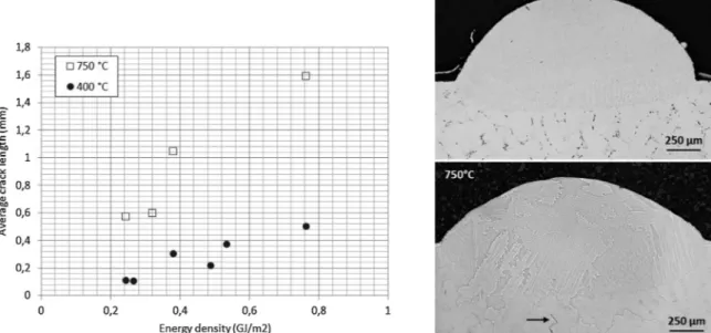
Additional tests were carried out with a pre-heating temperature of 750 °C and a 2 mm spot diameter (Fig. 10). Surprisingly, using a pre-heat at 750 °C induced a significant increase in crack susceptibility, together with a reduction of wetting angle.
This intensification of hot cracking at 750 °C might be explained by the ductility dip phenomenon occurring in the 600–900 °C temperature range for CM247LC and already mentioned byCarter et al., 2014on SLM samples andKim (2011)on wrought samples. This ductility dip (significant reduction of the elongation rate during tensile tests under quasi-static conditions) can be responsible for a high susceptibility to cracking during cooling of the beads. At temperatures above 900 °C, the ductility is expected to be recovered.
To avoid this deleterious behavior, two combined strategies have been adopted:
- Increasing the preheating temperature over 900 °C to avoid the ductility drop.
- Working at low laserfluence (less than 0.2 GJ/m²) by using lower powers combined to low scan speeds to further reduce the crack sensitivity.
Thefirst single beads carried out with a pre-heating temperature of 1050 °C have been shown to provide satisfactory crack-free micro-structures. Following such encouraging results, beads’ overlaps were performed to produce 3D deposits.
3.3. Microstructure of overlapped beads with high temperature preheating Different samples have been cladded with a multi-bead configura-tion, with a pre-heating temperature of 1050 °C and a reduced Fluence
Fig. 3. Laser cladding using induction heating. (a) Picture of the running process on a 100 × 25 × 15 mm sample (b) Typical heat-cycles recorded by the thermocouples posi-tioned on various locations at the surface of the sample (with 1–5 as follows: 1 (30 mm, 12.5 mm), 2 (2512.5), 3 (2012.5), 4 (15, 12.5), 5 (10, 12.5)) for a 10 min temperature plateau.
Fig. 4. Microstructure of as received CM247LC substrates (a) Fineγ' precipitates (≈ 60–65 % γ') in γ' dendrites, (b) Inter-dendritic zones with (Ti, Al, Hf) C carbides and coarseγ'.
of 0.1 GJ/m² (150 W, 50 mm/min), on 2 different substrates: 4 mm-thick (sample 1) and 2 mm-mm-thick (sample 2), both extracted from the initial stator (Fig. 1):
1 In the first case (type 1 samples) the material deposit exhibits li-quation cracks in the HAZ (Fig. 11).
2 In the second case (type 2 samples) clad layers are crack-free. This result was confirmed on four different samples with four cross-sec-tions on each sample, without observing any detectable crack (Fig. 12).
For both configurations, small (< 0.1 mm) spherical porosities (gas entrapping) are always observed in the deposit. A detailed analysis of sample 2 revealed a classical hot tearing of liquidfilms located in eu-tectic interdendritic zones, at the interface with largeγ' precipitates (Fig. 13).
4. Discussion
Results presented here above indicate that a repairing procedure is possible on CM-247LC (or Mar-M247) with temperature pre-heating of at least 1050 °C. However, depending on substrate thickness, local cracking in HAZ is still possible.
The reason why samples 1 (thickness = 4 mm) and 2 (thick-ness = 2 mm) behaved in a different manner with similar processing parameters can be explained by different options:
1 A residual stress effect: during solidification and cooling, clad layers are submitted to tensile stresses generated by the surrounding matter, which are enhanced by thicker substrates
2 Modifications of local thermal cycles due to specific heat dissipation during induction heating which generate different microstructural
effects, especially in terms of γ’ content.
For a deeper understanding of microstructural effects, a detailed analysis ofγ' precipitation was carried out. On the one hand, for 2 mm – thick crack-free samples (type 2 samples), the primaryγ' content is shown to be very low (≈ 16%) in the HAZ and just below the HAZ whereas a large amount of small (≈ 50 nm) γ' secondary precipitates are observed (Fig. 14a). On the other hand, for 4 mm– thick samples, the microstructure in and just below the HAZ is fully composed of 55–60 % primary γ' precipitates (size ≈ 500 nm), which content is very similar to the one of initial substrates. Consequently, for similar applied induction heating, it is assumed that different local thermal cycles T = f (x,y,z,t) were really applied to the substrates.
To further address this point, isothermal heat treatments have been carried out, using time holding of 15 min, 30 min and 60 min at tem-peratures of 950 °C, 1050 °C and 1100 °C, for 2 mm-thick substrates. Results indicate that a precipitate state equilibrium has occurred after only 15 min, and that dissolution ofγ ' tends to be effective only for T = 1100 °C and above (Fig. 15). This confirms that, for similar dura-tions as induction heating cycles, the dissolution of primaryγ ' pre-cipitates is not really effective below 1100 °C.
Consequently, one can assume that temperatures obtained on 2 mm-thick samples were locally higher than 1100 °C during induction heating, thereby leading to the dissolution of primaryγ' precipitates. Moreover, the precipitation of small secondary γ' precipitates is as-sumed to have occurred during cooling at−80 °C/min cooling rate. For 4 mm-thick samples, the larger thermal dissipation is supposed to have induce local temperature below 1100 °C, thus limiting primaryγ' dis-solution. In the present work, the use of induction heating at tem-peratures near 1050 °C, was not sufficiently precise in terms of applied temperatures, to ensure an homogeneous dissolution of primaryγ ' whatever the considered substrate thickness. At such elevated
Fig. 5. Examples of single fusion beads obtained without preheating on CM 247LC for two distinct laser diameters. (a) D = 4.6 mm, P = 1000 W, V = 100 mm/min (b) D = 2 mm, P = 700 W, V = 100 mm/min.
Fig. 6. Macroscopic analysis of single fusion beads for various laser powers and scanning speeds. Below macrographs are reported dilution rate values (=ratio of molten volumes Vsubstrate/Vtotal) - Preheating temperature =400 °C, D = 2 mm.
programmed temperatures, especially when a regulation is applied to reduce cooling rate, it becomes difficult to fully control local tem-peratures with a precision of less than 50 °C as shown in Fig. 16. However, and this is an interesting point, results tend to confirm that laser cladding can be carried out to refurnish cast CM247LC without inducing hot-cracking, provided local temperatures are increased up to
at least 1100 °C, and with the use of a controlled cooling rate. In short, the capability of laser cladding the CM247LC alloy was shown to depend on its local microstructure: for local pre-heating temperature below 1100 °C, dissolution of large primaryγ' precipitates was not sufficient to avoid hot cracking, whereas a sufficient dissolution was obtained for temperatures at least equal to 1100 °C. Such
Fig. 7. Metallographic cross section of a CM247LC single deposit (320 W– 50 mm/min – D = 2 mm, preheating temperature: 400 °C) after chemical etching with 3 zooms on liquation cracks in HAZ.
Fig. 8. SEM analysis of hot cracking in the heat-affected zone, (a) at low magnification with windows 1, 2, 3, (b) detail of zone 1 near the crack initiation, (c) detail of zone 2, (d) detail of zone 3 with a small crack in an interdendritic zone (P = 320 W– V = 25 mm/min – D = 2 mm).
preheating temperatures are rather close from the full γ’ dissolution temperature (1230 °C). In terms of pre-heating temperature, the current results are in relatively good accordance with arc welding procedures recommended in a patent bySmashey (1999).
5. Summary and conclusions
This work was aimed at defining an experimental protocol for the repairing of CM247LC aeronautic parts having a very high primaryγ' content (≈ 65%). In a first stage, considering single beads, many pro-cessing conditions (power, preheating temperature, spot size, scan
velocity) have been tested to identify conditions with the least crack sensitivity. Low laserfluence were systematically shown to decrease the crack sensitivity, but no crack-free samples could be obtained for pre-heating conditions of less than 900 °C.
In a second stage, considering induction preheating at 1050 °C programmed temperature, crack-free welds could be obtained in multi-bead configuration. This was attributed to a huge reduction of primary γ' phase (down to 15%). Such a result is assumed to be due to local pre-heating temperatures of more than 1100 °C. The present work con-firmed the ability of laser cladding + induction pre-heating to refurnish cast CM247LC alloy. Further optimization of the induction pre-heating
Fig. 9. Average crack length versus laser power and energy density for a 400 °C preheating and two laser spot diameters (2 and 4.5 mm).
Fig. 10. (a) Average crack length versus laser energy density for two distinct substrate preheating temperature (400 and 750 °C), and a 2 mm spot diameter, (b) comparison of single beads obtained at 400 °C and 750 °C (320 W– 50 mm/min – D = 2 mm): a subsurface cracking is evidenced at 750 °C.
Fig. 11. Metallographic cross section observation of sample 1 (preheating temperature =1050 °C, 4 mm-thick, 150 W, 50 mm/min, D = 2 mm): Liquation cracking in HAZ.
Fig. 12. Analysis of crack-free samples (samples 2, 2 mm-thick, 150 W, 50 mm/min, D = 2 mm) (a) metallographic analysis of 2 beads overlap (b) Macroscopic picture and (c) metallographic analysis of a 5 beads overlap (preheating temperature=1050 °C).
Fig. 13. Detailed cross section of Sample 4 (4 mm-thick, 150 W– 50 mm/min): location of liquation cracks in the inter-dendritic zones near large γ’ precipitates.
Fig. 14. Microstructure of CM-247LC after induction HT at 1050 °C on (a) 2 mm thick sample and (b) 4 mm-thick sample. On 2 mm-thick sample, the primaryγ ' content is near 16% and tiny secondaryγ' precipitates are formed whereas on 4 mm – thick samples the primary γ’ content is still close to 60%.
stage should be done to improve the whole process.
In the incoming work, longer induction heating time-maintains, altogether with more temperature measurements should be carried out to ensure a sufficiently precise and stable pre-heating in the 1100–1150 °C range. Moreover, after laser repairing with a 1100–1150 °C pre-heating, a full range of thermal treatments (stress relief…) should be applied to the repaired material to obtain the de-sired microstructure and the appropriate mechanical strength. Declaration of Competing Interest
The authors declare that they have no known competingfinancial interests or personal relationships that could have appeared to in flu-ence the work reported in this paper.
Acknowledgements
This work was done within the frame of the NENUFAR project
granted through the 19thFUI call. References
Basak, A., Das, S., 2017. Microstructure of nickel-base superalloy MAR-M247 additively manufactured through scanning laser epitaxy (SLE). 2017. J. Alloys. Compd. 705, 806–816.https://doi.org/10.1016/j.jallcom.2017.02.013.
Carter, L.N., Martin, C., Withers, P.J., Attallah, M.M., 2014. The influence of the laser scan strategy on grain structure and cracking behaviour in SLM powder-bed fabri-cated nickel superalloy. J. Alloys. Compd. 615, 338–347.https://doi.org/10.1016/j. jallcom.2014.06.172.
Danis, Y., Arvieu, C., Lacoste, E., Larrouy, T., Quenisset, J.-M., 2010a. An investigation on thermal, metallurgical and mechanical states in weld cracking of Inconel 738LC su-peralloy. Mater. Des. 31, 402–416.https://doi.org/10.1016/j.matdes.2009.05.041. Danis, Y., Lacoste, E., Arvieu, C., 2010b. Numerical modeling of inconel 738LC deposition
welding: Prediction of residual stress induced cracking. J. Mater. Process. Technol. 210, 2053–2061.https://doi.org/10.1016/j.jmatprotec.2010.07.027.
Ernst, S.C., Baslack III, W.A., Lippold, J.C., 1987. Weldability of High-Strength, Low-Expansion Superalloys.
Foster, M., Updegrove, K., 2001. Welding Superalloy Articles. US6333484 B1..
Gharbi, M., Peyre, P., Gorny Fabbro, R.C., Carin, M., Caron, D., Morville, S., Le Masson, P., 2013. Influence of various process conditions on surface finishes induced by the direct metal deposition laser technique on a Ti-6Al-4V alloy. J. Mater. Proc. Tech 213, 791–800.
Hagedorn, Y.-C., Risse, J., Meiners, W., Pirch, N., Wissenbach, K., Poprawe, R., 2013. Processing of nickel based superalloy MAR M247 by means of High temperature -selective laser melting (HT - SLM). High Value Manufacturing: Advanced Research in Virtual and Rapid Prototyping. CRC Press, pp. 291–295.https://doi.org/10.1201/ b15961-54.
Kim, I.S., Choi, B.G., Hong, H.U., Yoo, Y.S., Jo, C.Y., 2011. Anomalous deformation be-havior and twin formation of Ni-base superalloys at the intermediate temperatures. Mater. Sci. Eng. A 528, 7149–7155.https://doi.org/10.1016/j.msea.2011.05.083.
Li, Z., Gobbi, S.L., Richter, K.H., 1997. Autogenous welding of Hasteloy X to Mar-M247 by laser. J. Mater. Process. Technol. 70, 285–292.
Lippold, J.C., Kiser, S.D., DuPont, J.N., 2011. Welding Metallurgy and Weldability of Nickel-base Alloys. John Wiley & Sons.
McNutt, P.A., 2015. An Investigation of Cracking in Laser Metal Deposited Nickel Superalloy CM247LC (d_en). University of Birmingham.
Morin, J. (2009). Weld repair of superalloy materials. US Patent App. 11/497,113. Ojo, O.A., Richards, N.L., Chaturvedi, M.C., 2004. Contribution of constitutional liquation
of gamma prime precipitate to weld HAZ cracking of cast Inconel 738 superalloy. Scr. Mater. 50, 641–646.https://doi.org/10.1016/j.scriptamat.2003.11.025.
Owczarski, W.A., Duvall, D.S., Sullivan, C.P., 1966. Model for heat-affected zone cracking in nickel base superalloys. Welding Journal 45, 145–155.
Smashey, R.W., Kelly, T.J., Snyder, J.H., Sheranko, R.L., 1999. Welding of Nickel-base Superalloys Having a Nil-ductility Range. US5897801 A..
Fig. 15. Influence of isothermal heat treatments on microstructures of CM247LC (a) without HT (66% γ '), (b) 1050 °C – 15 min (57% γ '), (c) TT 1100 °C – 15 min (53%γ ').
Fig. 16. Examples of thermal cycles generated by the inductor and measured by pyrometer (1050 °C programmed temperature) with or without control of the cooling rate (without control : 80 °C/min cooling rate, with control : 25 °C/min between 1050 °C and 750 °C). Sharp temperature decreases are evidenced during the inductor heating.