Open Archive TOULOUSE Archive Ouverte (OATAO)
OATAO is an open access repository that collects the work of Toulouse researchers and
makes it freely available over the web where possible.
This is an author-deposited version published in :
http://oatao.univ-toulouse.fr/
Eprints ID : 15800
To cite this version : Tardy, Alain and Roboam, Xavier and
Zanchetta, Pericle and Boroyevich, Dushan and Burgos, Rolando and
Schanen, Jean-Luc and Wurtz, Frédéric and Sareni, Bruno and
Wheele, Patrick Towards More Optimization for Aircraft Energy
Conversion Systems. (2015) In: MEA 2015 - More Electric Aircraft, 3
February 2015 - 5 February 2015 (Toulouse, France)
Any correspondance concerning this service should be sent to the repository
administrator:
[email protected]
Towards More Optimization for Aircraft Energy Conversion Systems
Alain Tardy (1), Xavier Roboam(2), Pericle Zanchetta(3) Dushan Boroyevich(1), Rolando Burgos(1), Jean-Luc Schanen(4), Frederic Wurtz(4), Bruno Sareni(2), Patrick Wheeler(3)
1) CPES - Virginia Tech, 1185 Perry Street 655 Whittemore Hall (0179), Blacksburg, VA 24061USA, [email protected]
2) LAPLACE / Groupe GENESYS, ENSEEIHT, 2 Rue Camichel, 31071 Toulouse Cedex 7, France,
3) University of Nottingham EEE, Nottingham, NG7 2RD, UK, [email protected]
4) G2ELab, Université de Grenoble Alpes, Ense3 BP 46, 38402 St Martin d'Heres cedex, [email protected]
Abstract The impact of power subsystem design on aircraft performance has traditionally been assessed during
an aircraft’s conceptual design phase via estimates based on past design references and databases. With the advent of the more/all electric aircraft (M/AEA), the need to more fully integrate electrical power subsystems into the overall aircraft system greatly increases. However, determining impacts on fuel consumption and other aircraft level benefits during the conceptual design phase becomes significantly more difficult and cannot be fully realized on the basis of past design references and databases since they are insufficient for addressing the impacts of the new architectures and technologies involved. To address this lacuna, a comprehensive framework of methodologies, models, and tools is needed for this phase of the design process to quickly, efficiently, and with sufficient fidelity assess and optimize the mission-level conceptual design of the electrical power subsystem (EPS) and its integration into the overall aircraft system. This also requires a rethinking of the thermal management subsystem (TMS) due to increased heat loads relative to the EPS and the possibility of TMS electrification, which in turn requires a simultaneous consideration of both subsystems during the integration and conceptual design phase of system assessment and optimization. Further discussion on why this is of importance and on why we need such a framework now is given in this paper.
I. Introduction
Major improvements in aircraft performance have traditionally been brought about by progress in propulsion, structures, and aerodynamics [1]. Power subsystems are adapted to support associated aircraft configuration needs. For instance, the electrification of power systems is envisioned as a key enabler of more fuel efficient engines, lighter composite structures, the reduction of hydraulic power distribution weight and weaknesses, etc. [3]. Electrification rationalizes the energy processing architecture, facilitates higher integration between power systems, and brings all the advantages of electrical technologies to the various power subsystems. More integration is spatial (for weight and drag reduction), functional, and temporal (new energy management) [2, 3, 4, 5]. Aircraft fuel consumption efficiency improvement requires more integration between power subsystems through their electrification [3].
II. The need for a new EPS design and methodology
i. We are at the beginning of the (M/AEA) S
curve.
The EPS of the M/AEA aircraft is more complex as indicated per Figure 1 below (i.e., has more components and much more electrical network configurations) and more critical. Most aircraft
functions are dependent on electrical power availability. EPS resources and loads are functionally and physically linked in a complex fuel efficient energy management scheme [3, 4, and 5]. Processed electrical power and voltage level are much higher: Thus, electrical faults are more dangerous.
Figure 1 Legacy electrical system(top) versus more electrical aircraft electrical system (bottomt) (Source LAPLACE)
New high voltage DC networks and converters are required to achieve efficiency and weight, the majority of the power load is via electrically motorized and electronically controlled actuation which avoids the technological weaknesses of hydraulics and pneumatics. However, load and source management complexity is strongly increased [4]. E-engine start, e-hydraulics generation, APU, taxi, brake, E-WIPS, E-ECS, and E-flight actuation are good examples of the all the electrical trends.
Figure 2. Legacy power aircraft (top) and MEA power aircraft (bottom) (Source LAPLACE)
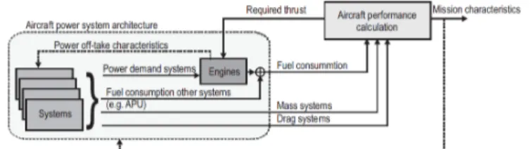
Figure 2 [5] illustrates the state-of-the art in replacements of the hydraulically and pneumatically powered systems by electrically powered ones.This electrification is a first step in the AEA roadmap in which the previous ATA functional allocation, sub-system architectures standards and rules for design and certification are still being used. Figure 3, below on right side shows the linkage between systems weight and drag, power off-take, systems power demand, thrust and induced fuel consumption. It is now admitted that electrification is still at the beginning of its S curve while the traditional hydraulic pneumatic and electrical technology mix is ‘saturating’: no further significant progress are anticipated.
Figure 3. Energy Coupling between Subsystems, Engine and Aircraft (Source PHD dissertation, Hanke - Liscouet)
ii. Synthesizing the EPS for an optimal
aircraft is a complex process which requires new design methodologies
In the end, the EPS design must maximize electrical power availability and “affordability”, respecting load supply mission and safety rules. Safety and availability have strong implications on the spatial and functional implementation constraints and the rules for systems segregation, dissimilarity, maturity, and power sizing [2, 3, 4, 5, 66, and 83]
Being “more affordable” for a commercial aircraft, the EPS design must minimize its induced fuel consumption through minimized power extraction over the mission and by mean of minimal induced weight and drag. [3].
Analysis of electrification fuel efficiency benefits is not straight forward. The EPS system design has consequences on others aircraft systems, inducing additional weight, drag and power extraction and reversely design others subsystems, engine and aircraft design choices impact strongly the EPS components power sizing and associated induced weight, drag and power extraction.
We give hereafter several examples of this performances linkage:
- Replacing the bleed air deicing solution by electro-thermal deicing is due to the use of composite materials and is done to be more efficient. However, feeder and generator sizes and weights are strongly impacted. Power shaving to reduce oversizing is dependent on possible load shedding in the worst case operation with limited generated power and icing conditions. At the aircraft level, the weight savings due to composite material use, the fuel consumption and weight reduction due to the no bleed more efficient engine, and the weight reduction of
the deicing system itself are expected to positively offset the additional weight and drag of the electrical generation system. - Bus voltage , distance to load , distribution
architecture are EPS design variables impacting weight of wiring between power distribution centers and load
- Regenerated energy management choices,
EMC and power quality design
performances and constraints ,location of power storage, not interruptible power bus architecture, location of load converters and its potential time sharing are EPS design variables impacting induced weight and drag of the load electrical power conversion and storage means
- Location, Dimensioning and efficiency of EPS components depends at first of available thermal interface impacting the induced weight and drag of the heat extraction, transport, storage, recycling means of the TMS
- Choices of the electrical generation sources implementation and usage versus missions phases and system status are dependent of the induced drag and weight to install electrical power generation means (e-APU, ME gearbox, fuel cell induced drag , weight and losses )
Modular fault tolerant system mutualizing resources for several subsystems are improving hosted functions availability and robustness. IMA is one example of such principle application. EPS and TMS future architectures may leverage on similar principles. [66]
In summary, electrification of all systems for affordability and availability respecting load supply mission and safety rules implies complex load, source, and conversion resource management and EPS co design with others systems, engine and aircraft. This is extremely difficult to realize without further expert simplifications and an adapted “to be developed” conceptual design framework.
iii. TMS share with EPS the same system
design synthesis and integration
problematic as described above
Similar to the EPS, the TMS is, of course, also an energy management system that processes energy to all aircraft power systems: as to the efficiencies of both electrical and thermal energy conversion, they must be maximized through technology, architecture, dimensioning, and resource management in a designed coordinated strategic way [45-49].
The diagrams of Figure 4, on right side, shows the various integrated cooling loops as well as the various power links (electrical, thermal and mechanical) between power subsystems for a modern military aircraft.
Design of the TMS is more and more challenging as heat storage and rejection capabilities are reduced while heat loads are increased [8]. The criticality of the increased heat load for a typical state-of-the-art military aircraft is illustrated in the diagram in Figure 5, on the right side. On civil aircraft, heat loads are
also increasing while the search for greater fuel efficiency leads to less heat removal or storage capability.
Figure 4. Thermal management cooling loop integration. Power link architecture between Sub-systems for a military aircraft [6]
Consequently TMS is the main electrical power consumer in the first step of the M/AEA aircraft roadmap.
Figure 5 Military aircraft heat load increase [7] At present, little research is focused on the full integration of the EPS even though as thermal energy processing time constants are compatible with EPS load management time constants (several tens of seconds to several tens of minutes), and as technologies are emerging for more efficient energy conversion from heat to electricity and conversely, thermal energy conversion, transport, storage, and fuel efficiency could be further improved.
We give hereafter principles of potential improvements in architecture and technology through deeper integration between TMS and EPS:
Since temperature and pressure conditions as well as heat load are constantly changing throughout the mission, the simultaneous design optimization of the EPS and TMS would take advantage of benefits resulting from the coupling of thermal (i.e., storage, extraction, recycling, and rejection) and electrical energy management to reduce peak power demands and overall installed energy conversion, storage, and transport capacities: For instance a possible solution to the shortage of energy storage could be to actively cool heat storage reservoirs via thermal and electrical resource management during a mission.
More integration between the EPS and a more electrified and more electronically controlled TMS would enable further automation, regulation and monitoring of thermal energy conversion and transport means.
Modular time share resources, reconfigurable thermal energy links would be implemented in TMS to further decrease the TMS installed weight and induced drag, and to increase TMS functions availability. this TMS
resource management would be optimally
coordinated with the EPS resources management Thermoelectric generators and coolers could be extensively used for temperature control either to cool power electronics or any specific “local” area/volume which need to be temperature controlled.
iv. Conclusion of section II
The latent synergies with the TMS described before are opportunities to be investigated with new thermal electric technologies and combined heat-electrical energy management.
The performance coupling between EPS, TMS, other electrified power subsystems, engine, and aircraft increases the complexity and criticality of the EPS
and TMS architecture, management, and
dimensioning synthesis.
This EPS-TMS aircraft integrated design extremely difficult: It would require expert design problem simplifications and an adapted “to be developed” conceptual design framework.
In order to explore the EPS TMS conceptual framework, models and methodology characteristics need, the next sections of this paper will review: the state of the art for design synthesis of electrical component and sub-systems(in following section III) the design issues linked to semi-automated design synthesis through optimization of the EPS (in section IV)
the implication of power sub-system integration (in section V)
III. Electrical component and sub-system design state of the art
Design of a power electronics converter, an electrical machine, an electrical sub system consists in the selection of architecture, structure, topology, management, controls, technologies, component and component dimensions.
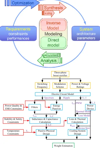
This is generally achieved through iterative designs based on expert design choices, components selection and calculation procedure for weight dimensioning similar to the design synoptic given in Figure 6. (Bottom)
Then the estimated design (direct model) is simulated or prototyped to obtain performance. Through iteration, initial design choices are tuned to get the final design parameters, structures and components to meet objectives.
In some elementary cases, the inverse model is straight forward and design can synthesized directly .If this inverse model is not available as some times it is not feasible, a combination of direct and inverse models can be used to solve the inverse problem
using an optimization loop as shown below right side in Figure 6 (Top part)
Automated design synthesis through optimization methodology has been initially developed 30 years ago when the exploration of the design space more efficiently through automated mathematical tooling has been enabled by both explosion of computation capability, availability of optimization algorithms and mathematical theorem to solve the inverse problem. in Figure 6 (bottom part) below : the design procedure (here a mix of direct and inverse sub-models) is made of equations linking converter selected design variable (yellow color) such as switching frequency and converter design constraints (red color) such as high frequency current limit or stability margins to calculate weight of the various component. The blue box in Figure 6 includes the various equations to calculate converter components values dimensioning and associated weight.
Three-phase boost rectifier Modulation Scheme Switching Frequency
Power & Voltage Ratings
Power Quality & EMI Constraints
Stability & Safety Constraints Temperature Constraints Power Device Filters Energy Passives
Loss & Thermal Calculation Inductance & Capacitance
Calculation Cooling System Design Passive Physical Design Weight Estimation U, I Spectrum Loss Model Electric Circuit Model
Ripple U, I fsw, PWM RthHS fcorn L,C L,C Ta Thermal Model Device Size
Figure 6: Top: the inverse problem solved by an optimization loop. Bottom example of a mixed direct- inverse model to be used in optimization loop to solve the inverse problem (Source CPES & LAPLACE) This components selection and calculation procedure for weight dimensioning can be used in an optimization loop for design synthesis of the best design variables values combination that minimize the weight objective while meeting constraints. Design procedure can be extended, modified for any set of component design objectives, constraints and variable and then used in an optimization loop to automate the search in the accessible design space.
Other examples of such design procedure are shown below next page in Figure 7, Figure 8, and Figure 9. One typical weaknesses of the legacy non automated design synthesis using iterative calculation or simulation of the direct model to verify performance is that it is more time consuming than using an automated search in the design space. As it is more time consuming, optimality is not guaranteed as the design space is too partially explored due to development time and cost constraints. The other drawback is that system properties and limits than can observed through systematic exploration of the design space are less visible.
However, the automated design synthesis by optimization loop is not yet the typical methodology used for electrical system and component design synthesis.
Definition the design problem procedure that can be automated in an optimization loop is not always easy and requires expertise and validated methodology, models and a design framework. If the design problem is poorly defined, if the sizing model, the selection procedure are too large or too complex, if the optimization algorithm is not adequate then design may be not or poorly synthesized. In Section IV of this paper, the design issues of an automated or
semi-automated design synthesis through
optimization algorithm are reviewed.
Several examples of converter or electrical machine automated or semi-automated design synthetizing studies papers are given in references [9 to 44] In those examples, appropriate design calculation and selection procedure of converter, electrical machine or part of it are developed to solve the inverse problem: the review shows since 2000 a constant but slow progress and academia slow adoption of this design synthetizing methodology for power converter and machines. The formulation of design problem, the associated assumptions, also the justification of the chosen optimization methodology and of the optimality of synthetized design are aspects not always detailed and explained. Indeed adoption of automated design synthesis through optimization is slowed by:
• continuously growing performance of the CAD tools allowing fast verification of design variants
• design space constraints due to industry and in house standards
• lack of time and expertise to develop appropriate model for inverse problem solving,
• missing knowledge to optimize at system level,
• lack of design framework supporting all needed plug in plug out specific application tools.
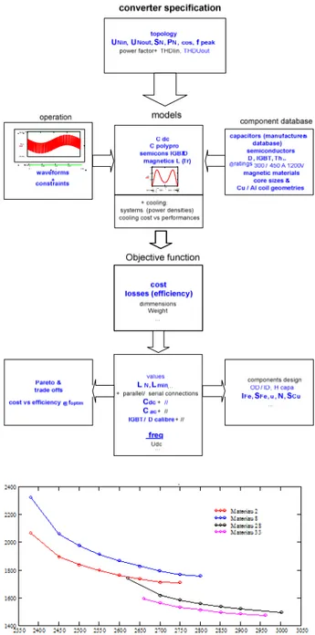
Some research group are very active and prone this design synthetizing approach for converter, machine and electrical subsystem. For instance in [36] (2010) Kolar demonstrates the interest of using design by optimization methodologies to study competitiveness of a given set of technologies for a given system and mission: Parameters defining variability of converters system structure by converters association are potential variables of the multi objectives performances optimization.
System power normalized performances are selected as output power density:ρ, output power weight density:γ, efficiency:η, failure rate:λ and $/KW:σ as main performance indices. System Pareto front hyper surfaces between the performances indices can be used to find the technology nodes (ρ,η,σ, fs): finding switching frequency that minimize cost/kw on the Pareto hyper surface is the proposed definition for a technology node (ρ,η,σ, fs); Design by optimization methodology could be therefore used for road
mapping by analysis of the performances
improvement associated to new technologies improvements through Pareto curves of different potential structures.
Figure 7: Synoptic of synthesis of converter design variants to obtain Pareto front cost versus efficiency. 300KVA NPC inverter cost versus losses Pareto front (Source G2eLab, Guillon)
The multi objectives multi-constraint multi variable optimization frame-work could allow by technological constraints sensitivity analysis, the definition of system improvement achievable by improvement of the technology.
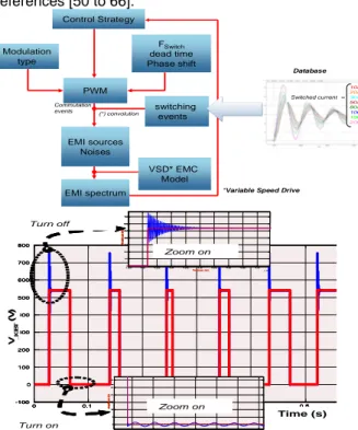
Electrical components and component assemblies design synthesis methodologies and framework requirement analysis can be founded in the following references [50 to 66]. Control Strategy Modulation type PWM FSwitch dead time Phase shift switching events EMI sources Noises EMI spectrum VSD* EMC Model (*) convolution Commutation events 10A 20A 30A 50A 80A 100A 150A 200A Courant charge = Switched current
*Variable Speed Drive
Database 0 0.1 0.2 0.3 0.4 0.5 -100 0 100 200 300 400 500 600 700 800 Temps (s) A m p li tu d e ( V ) Time (s) V_ IG B T (V ) 4.325 4.33 4.335 4.34 4.345 4.35 4.355 4.36 4.365 4.37 x 10⁻⁴ 0 100 200 300 400 500 600 700 Temps (s) Am plitu d e (V ) 4.7155 4.716 4.7165 4.717 4.7175 4.718 4.7185x 10- 4 0 5 10 15 20 25 30 Am plitu d e (V) Ouverture Fermeture Turn off Turn on Zoom on Zoom on 0 0.1 0.2 0.3 0.4 0.5 -100 0 100 200 300 400 500 600 700 800 Temps (s) A m p li tu d e ( V ) Time (s) V_ IG B T (V ) 4.325 4.33 4.335 4.34 4.345 4.35 4.355 4.36 4.365 4.37 x 10⁻⁴ 0 100 200 300 400 500 600 700 Temps (s) Am plitu d e (V ) 4.7155 4.716 4.7165 4.717 4.7175 4.718 4.7185x 10- 4 0 5 10 15 20 25 30 Am plitu d e (V) Ouverture Fermeture 0 0.1 0.2 0.3 0.4 0.5 -100 0 100 200 300 400 500 600 700 800 Temps (s) A m p li tu d e ( V ) 0 0.1 0.2 0.3 0.4 0.5 -100 0 100 200 300 400 500 600 700 800 Temps (s) A m p li tu d e ( V ) Time (s) V_ IG B T (V ) 4.325 4.33 4.335 4.34 4.345 4.35 4.355 4.36 4.365 4.37 x 10⁻⁴ 0 100 200 300 400 500 600 700 Temps (s) Am plitu d e (V ) 4.325 4.33 4.335 4.34 4.345 4.35 4.355 4.36 4.365 4.37 x 10⁻⁴ 0 100 200 300 400 500 600 700 Temps (s) Am plitu d e (V ) 4.7155 4.716 4.7165 4.717 4.7175 4.718 4.7185x 10- 4 0 5 10 15 20 25 30 Am plitu d e (V) 4.7155 4.716 4.7165 4.717 4.7175 4.718 4.7185x 10- 4 0 5 10 15 20 25 30 Am plitu d e (V) Ouverture Fermeture Turn off Turn on Zoom on Zoom on
Figure 8. Synthesis of equivalent EMI noise source to calculate filter component value. Top: principle – Bottom: illustration in the time domain (ideal voltage -red and reconstituted voltage -blue) (Source G2eLab Toure)
Figure 9: Design procedure to optimize EMC filter volume (Source G2eLab Toure)
In particular, Roboam in [4,5,and 53 ] analyses the technological and architectural trends of the more electrical airplane and describes the “integrated design by optimization” methodology: ”it consists of
coupling the dimensioning models with an
optimization loop to optimize system objectives such
as weight, losses, others, while satisfying
technological and operational constraints (thermal, power quality, stability, EMC)”.
Authors give two examples of such optimization at sub-system level; one is a power channel as shown below in Figure 8 [53] and [64]. Sensitivity to harmonics level requirement constraint is analyzed through optimization. Design integration is made between generator, rectifier and filter to minimize overall subsystem weight and losses.
Figure 10: Optimization of a HVDC power channel sub-system (G2eLAB Laplace Dissertation Hieu ) Another example is an ECS sub-system consisting of an electrically motorized compressor. The ECS sub-system design is optimized for minimum losses and weight over the mission. Results are shown in Figure 11.
Figure 11: Pareto optimal solutions for the ECS system: (a) Pareto optimal HSPMSM solutions, (b) Pareto optimal input filter and VSI solutions, and (c) Pareto optimal ECS solutions.
As already mentioned above, as off today EPS design is not done yet using automated or even semi-automated design synthesis through optimization:
- Synthesis EPS architecture and
management in a semi-automated way is still a subject of research.
- Dimensioning optimization is done at component level not at subassemblies power chains as component interfaces are constrained by standards issued of past references.
During the preliminary design phase of the development process of an aircraft, initial trade studies between potential architectures are achieved through a mix of expert review of potential
architectures adapted from previous similar aircraft, and in house design rules.
- Potential improvements of new technologies are evaluated in delta performances at a subsystem level;
- Spreadsheet load analysis of mission point method and other design standards permit to size the power rating of components and associated weight, volume and losses. - Simulation using the direct model then
allows to verify some aspects of the power quality and stability, and EMC can be evaluated after the preliminary design phase.
However interest for aircraft power subsystems design synthesis through optimization methodology is emerging as described in the following references [3, 67 to 83]
We describe hereafter two analysis of EPS semi-automated design synthesis as examples the emerging trend of semi-automated design synthesis for Power subsystems:
In [3] (2008) Hanke-Liscouet describes the characteristics of a design framework for the design synthesis of the power sub-systems taking in account coupling between subsystems, engine and aircraft: A generic multi energy bidirectional power system module is used to model all main power conversion functions of the aircraft. The model includes the relationships between input power, output power, a set of aircraft level input and system level inputs; the power system module computes weight, drag associated to power flow using simple algebraic equations and can be used in the direct and inverse way as it is implemented as a Dymola/ Modelica object.
Figure 12: Inverse problem to design power source (Hanke-Liscouet 2008) through surrogate power flow models
As shown in Figure 12 above, the proposed methodology uses a coupled two steps process: First, power to be installed, associated weight and drag, and required fuel mass are obtained using “inverse” simulation depending on the output power. Then using the above system design, simulation estimate the system performance at aircraft level (losses and consumed power). For optimization and evaluation of changes, the two processes are coupled. In this way, the impact of overall aircraft top-level changes, of overall power architecture choices or even of system parameters is calculated directly and in a transparent way. To assess the changes in mass, drag and secondary power off-take on the engine, the power system architecture calculation process is linked to an aircraft performance calculation that computes the required thrust for flying the defined mission. The
above design synthesis is similar to the legacy manual iterative sizing, structure selection and performance assessing .design by optimization methodology is not used as the inverse model are available due to the use of simple power flow equation and parametric linear sizing model .Architecture from current design references are assessed in performance not synthesized .
In “Methods and tools towards optimal design of aircraft electrical network” dissertation, a first example of EPS architecture design synthesis by optimization is given: Giraud investigates optimization of the load allocation at aircraft level using bond graph modeling and knowledge based classification methodologies to optimize the load allocation to bus bar and the source to bus bar allocation. The objective is to minimize the installed weight due to load combination power flow (feeder, generator, power center dimensioning). [54, 65, and 66] (2014)
The “simultaneous processing” between architecture, dimensioning and management is difficult if not impossible to implement.
This study shows that stated problem needs to be simplified by designer expertise to reduce the search space:
- Reducing system complexity is a goal - Safety and business rules can for instance
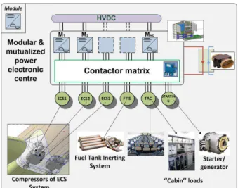
reduce the space of possible allocations. The optimization of a modular power center as shown in figure 13 below (left and right side ) is also a design synthesis challenge as it combines both high combinatorial possible choices of reconfiguration cases and multi-physics system dimensioning. [66]
Figure 13 Power center with VSI modular resource (Source LAPLACE Phd dissertation Giraud)
We will now review the general design issues linked to semi-automated design synthesis through optimization for a subsystem.
III. Review of general technical issues linked to
semi-automated design synthesis through
optimization
- the definition of the design problem and how mission and environment description are translated to design objectives and constraints. - the development of one or several single or
multilevel models adapted to continuous or combinatorial inverse problems to be solved through optimization using one several optimization loop in parallel, the associated design loop management strategy.
- the development of tools and methods to deal with complexity and uncertainty, to enrich low fidelity model.
i. Definition of the design problem:
objectives, variables, constraints
formulation
EPS and power subsystems design has to take into account more than one “nominal” operating point but a simultaneous set of equivalent trajectory of each design drivers: to build the proper design driver vector for dimensioning, part of design constraints have to be “integrated” along the mission.
Also the relationship with the system design versus mission and environmental constraints is bi-directional: the EPS mission may be executed in different ways impacting its design choices; specific design choices may lead to a better mission capability which was not expected at first.
Defining the approach to capture the key performance and dimensioning drivers from mission profiles and environmental constraint is a research by itself: statistical method, sensitivity analysis and optimization can be mobilized to synthesize those mission and environment representative design drivers.
Additionally the “environmental” constraint is a mixture of true physical environmental constraints, artificial constraints from standards and certification rules, and the induced constraints from the interaction with the aircraft and its systems.
Among artificial constraints, electromagnetic emissions and power quality public standard are imposing severe constraints on the design and dimensioning of converter and switches. Improvement in power density and some design simplification may be achieved through revision of those standard. Those standards are mainly addressing the component to guarantee the system operation. Design validity is demonstrated by a combination of test, simulation and associated analysis mainly in normal operation, assuming the protection system will confine and clear a hazardous interaction.
Design by optimization methodology can be used to analyze interactions between mission, design constraints and performances within a complex environment by making the appropriate constraints variable, runs sensitivity analysis and optimization to find the optimal combination.
Note that generally, the number of objective functions has to be limited, most design issues shall be specified as constraints; for a given design problem, objectives selected shall be not compatible naturally. The choice of input variables has to be in accordance with the problem to solve with all performance criteria, sufficient but limited with no redundancy to limit complexity.
ii. Models and algorithms
For continuous problem solving, analytical and semi-analytical models are preferred for many reasons, computation time, explicit characteristic giving insight and understanding of the relationships between models parameters, ease to build and couple multi-physical models.
The disadvantage of analytical and semi-analytical models is its development time, its reduced generality and fidelity level in respect to FE numerical models: FE models can be used to enrich or to validate a simplified analytical model.
Numerical models are preferably used for validation of the dimensioning to reduce the number of real prototypes.
In general, it is researched to use of generic standardized models. Several level of modeling are necessary to cover the different system aspects. Coordination between the different models for the simultaneous design is part of the optimization strategy, and of the different steps of architecture, dimensioning, management co synthesis.
In order to solve multi modal problems sometimes involving discrete variables in the architecture and management synthesis, a hybridization of algorithms such as SQP (Sequential Quadratic Programming) - NSGA–II (Multi-objective Genetic Algorithm) is generally needed to fully and efficiently explore parameter space and to find rapidly the most powerful solutions.
For highly combinatorial design problems, different models and algorithms methodologies and tools from artificial intelligence have to be used: bond graph description, expert systems using inference engines, and specific meta-heuristic algorithms.
A FOM assessment of some commonly used algorithms is shown in Figure 14 below.
Figure 15 shows a simplified view of algorithms typology per type of design problem.
Figure 14: FOM of commonly used algorithms (Source L2EP G2elab [63]
Figure 15: Simplified view of algorithm typology (Source L2EP G2elab) [63]
iii. Methods to manage uncertainty
The source of uncertainties is multiple either linked to new architectures and technologies environment, mission, tolerances on parameters, or to modeling errors. Specific indicators such as Taguchi’s signal to noise ratio can be used to evaluate robustness of a solution in a given vicinity.
Recently, probabilistic approaches were established to acknowledge the problem of uncertainty and to support informed decision making in conceptual and preliminary design of aircraft and system architectures. [3, 70]
iv. Simultaneous synthesis is desirable
Energy conversion system design generally uses a sequential approach: first the functional analysis to build functional, logical, and physical architectures, then dimensioning and finally energy management. However, simultaneous design of architecture, dimensioning and management in interaction with mission profile opportunities is “desirable” to reduce the number of iteration and have a higher probability of reaching an optimal design.
One way could be to use design by optimization methodology (multi- system objectives multi design variables under constraints to simultaneously define dimensioning, management and architecture) [55]. As shown the Giraud dissertation [66], EPS semi-automated design synthesis is still a research subject for the architecture and the management; solving it requires design space limitation through application of safety and business rules, and will use new methodologies and tools from artificial intelligence: expert systems using inference engines, and specific meta-heuristic algorithms.
Generally to enable simultaneous design by optimization, we need to use analytical or semi analytical fast models of reduced complexity such as power flow, or simplified electrical models not including detailed control loop aspects. This level of accuracy and complexity may not be sufficient: More detailed models for part of system components may have to be used in a second step to further improve the design, which can then be difficult to solve in a simultaneous optimization process.
v. Simplification of System complexity
Where there is the need to break down a very large optimization problem; there are several methods to achieve this target:
- One is to assemble simplified models for each subsystem to build a new surrogate one for the overall system.
- Another one well suited to complex problem is Target cascaded optimization [56, 63]: it maintains the hierarchic breakdown and manages the interaction between the various sub problems during the optimization. Each sub problem can use its own algorithm. Objectives are set for each optimization sub process and all associated responses are propagated to each sub system until the sublevel target has become identical. The local optimization for each subsystem tries to zero the gap between the local optimal result and the download upper level objective. Multilevel design by optimization perform the optimization using multiple loops with models which may be different in accuracy, complexity, and computation speed and which may belong to various fields of expertise.
vi. Surrogate model fidelity enhancement
The first main use of multi-level approaches is not to breakdown complexity: It is used to correct a very simple surrogate model, for example by using the response of the correspondent FE model. Several methods exist: one method is to build an improved model prior to optimization. The model building makes uses of response surface methodology or other mathematical methods of approximation: Diffuse Element, Kriging, Artificial neural networks, Radial Basis functions network, efficient global optimization methods have been used in electrical engineering.
Another type of method is Space Mapping [55, 56, 62, and 63]; optimization is carried out using a simple model: every 10 optimizations typically, the results are compared to the fine model for alignment. The alignment process itself is performed through an iterative optimization process which minimizes the gaps between the two models, the so called “parameter extraction.” Several kind of Space Mapping are available, among which ASM, AM, MM.
All methods to enrich a surrogate model using FE, are very interesting because it will further enable larger use of the methodology design by optimization.
vii. Inter-operability, distributed optimization
Simulation tools like MAtlab / Simulink, Cadence, Amesim, Saber, Simplorer, Pspice, Portunus, Flux 2D/3D are environment based tools which have poor interoperability. Therefore, those environment based tools are not suitable to solve efficiently multi-physical multilevel model optimization problems, which requires indeed a strong interoperability with all major environment based tool such as listed above.
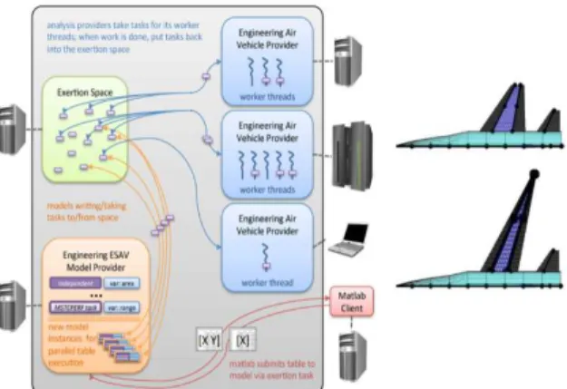
Figure 16 Left: SORCER uses Exertion Space to provide a flexible, dynamic space computing facility for ESAV optimization studies, Right: the ESAV optimization result half-span plan forms: baseline 1550 midrange (top); optimized 2500 mi range (bottom). [84]
In addition, the capability to be executed in a geographically distributed approach [84] is nowadays essential for a design collaborative platform, and environment based tool are limited to execution on a single computer.
viii. Automatic generation of the derivatives
One key differentiator of a design framework for optimization of continuous problem is the generation in an automated way of all the derivatives for a majority of models input description types by including in the frame work all mathematical computation capabilities required to support the computation of that derivatives.
Figure 17: Interoperable Cades Framework (Source G2elab)
With that feature, each component of the optimization model can be very efficiently optimized using gradient approaches allowing deployment of efficient multilevel optimization strategy on large systems. Use of hybrid SQP + Genetic algorithm further increase the frame work capability to enable efficient hierarchical optimization of large system, in which model component may include discrete variables. CADES tool is one example of such a framework [59, 61, 62, and 63]
ix. Framework characteristics and limits of
the approach design by optimization
The framework shall be made of software component building blocks, designed for the standards that guarantee interoperability with other modeling and calculation “environment“ type tools, offering plug in plug out capability for other applications in addition to its own applications. The tool has to enable adaptation of design optimization problem capture to the particular case and to support large multilevel model hierarchies. Its mathematical capabilities allied to its enhanced interoperability through plugin-plug out smart interfaces for model capture or export, will free the designer to concentrate on the design problem formulation where there is very large creativity space and to enhance both the description of the optimization problem and the structure of the model.
x. Summary and limits of design by
optimization methodology for subsystem
The first step is to correctly describe the design problem, then to establish the right model and model hierarchy to be used in optimization loops with the right sequential combination of algorithm. Mathematical methods exist to manage uncertainty and develop appropriate surrogate models. For a given formulated optimization problem with the appropriate mathematical tool, the search algorithm will find the best solution in the specified search space: This does not guarantee the optimality of the solution if the problem is not formulated correctly, or if the model is deficient to capture with enough accuracy all relevant aspects.
The designer may be satisfied by the best case of a poor description of the problem or by local optima well below what could be achieved with a larger design space, and a better search strategy.
Design by optimization methodologies can be found in the following paper, dissertations and academia research summary and justification description: [from 49 to 84].
IV. The implications of power sub-system integration
As described in section II of this paper, one EPS major design evolution consist in more functional, spatial and operational integration with others power sub-system in particular the TMS.
As indicated above interest for aircraft power subsystems design synthesis through optimization methodology is emerging as shown by references [3, 67 to 83]
Performance and interest of such more integrated power systems would be assessed at aircraft level for validation compared to legacy less integrated power sub-systems.
Although systems integration has been already identified as a major trend to increase fuel efficiency, study of more integrated aircraft power sub-systems is still not publically released, neither disclosed. During conceptual and early preliminary aircraft design, overall sizing of the aircraft’s configuration arrangement, size, weight, and performance are estimated. Alternative design concepts are prepared in response to the design requirements, and
variations on those concepts are analyzed. The required accuracy of e.g. predicted weight, performance or size is only of secondary importance. The expected level of accuracy in conceptual and early preliminary aircraft design usually lies between 10 and 15 % [70, 76, and 77]
Today sub-systems design has largely been neglected in conceptual and preliminary aircraft design due to its maturity and standardization gained over decades. Statistical relation were used to estimate only systems mass [70, 78]; other repercussions of systems integration were neglected. With more electrical more integrated subsystems trend, past references of the legacy aircraft are now irrelevant.
Developing a power subsystem model or a set of models usable at Aircraft MDO level is necessary to improve aircraft MDA [70]. This model of the EPS and associated aircraft power systems should permit to take in account relevant effects such as induced weight, drag and power extraction, and impact on gravity center during aircraft concept tradeoffs [70]. EPS Phenomena below the second range for power extraction and drag effects of power sub-systems do not need to be captured for optimization at Aircraft MDO level or for integration with others power subsystems.
Sizing requirements are “emerging” consequences of system and component failures modes analysis, and are dependent of architecture [83]
Equivalent quasi steady state power flow model with 10% accuracy may be sufficient to identify best architectures and technologies couples. Induced weight and drag shall also be estimated within a 10% range which for new architecture and technologies. To reach 10% accuracy with fully new architecture and technologies will require detailed dimensioning of the integrated power sub-system.
Figure 18: Efficient Supersonic Air Vehicle N² diagram (Source MAD center VT [79])
To synthesize and integrate the power sub-system model to be used at Aircraft MDO studies level various approaches are possible: The capability to perform subsystem sizing and analysis can be done in parallel and sequentially with tradition aircraft and
propulsion system sizing and analysis or
simultaneously by integrating the various subsystems models in the aircraft MDO framework.
This last option is the approach proposed in [70] by Lammering (2014) “Integration of Aircraft Systems into Conceptual Design Synthesis” where a MICADO framework is proposed to host the loosely coupled
systems. The author describes in details its modeling approach of the various systems based on technological equation of past designs. One drawback of this method is that the introduction of a new integrated new architecture between the electrified power systems is not really covered. A similar approach is proposed by Chakraborty [80] (2014), De Tenorio [81] 2010. Model Center is an example of such a frame work [81].
Another solution could be to first synthesize a detailed design of the integrated power subsystem, using a simplified model of interaction of power subsystem with aircraft and engine and then to establish a surrogate model to be used at aircraft level.
To study the new architecture of the integrated power subsystem, low or medium fidelity model could be first used as long as accuracy is not yet critical (10 to 15%): It is far more important to show the correct trends and effects within the investigated design space for valid optimization and down-selection. [70, 76].
A simplified parametric model of engine and aircraft is also needed to study the influence of engine and aircraft configuration on the power subsystem definition and to classify the integrated power subsystems architecture variants
The above approaches will help better MDA at Aircraft level during the concept phase and better design of the integrated power subsystems including the EPS.
V. Conclusion
In this paper we have review the stakes of going more electrical, and more integrated for the aircraft power subsystems, the need to take into account power links between engine, aircraft and power subsystems to synthesize an integrated power subsystems architecture.
MDO (Multi-disciplinary design optimization) methodologies are used to Aircraft design level to address interaction between the various disciplines with fast surrogated models, exploring large design spaces [6, 7, 70, 71, 76, 80, and 81].
The recent use and the current limits of design by optimization methodology to synthesize EPS architecture, management and dimensioning within an integrated aircraft power system have been analyzed. One issue of performing power subsystem integration optimization could be availability of meaningful model for engine and aircraft.
Few research are currently made for deeper integration of the power subsystems: Although for instance thermal energy conversion, transport, storage system fuel efficiency could be further improved through:
- Integrated design synthesis of the thermal and electrical energy conversion system: as thermal ,pressure conditions and heat load are constantly changing along mission, heat load storage extraction, recycling and ejection management may be coupled with electrical energy management to reduce peak power demand and overall installed energy conversion, storage, transport means - New architectures and functions
- Electrical technologies for high performance VCS and air-cycling machines, electrical technologies for temperature control. The stakes of this ATA transverse integration may be much higher than those linked to EPS direct optimization such as EMC filtering or Power Quality Optimization.
The required competences to optimize the integrated power sub systems are multidisciplinary and does include strong electrical and thermodynamic engineering competences.
Opportunities lies in new architecture and technology couples that enable better performance at aircraft level. This power sub-systems ‘deeper’ integration optimization is proposed as a field for such opportunities.
References
[1] Realizing Europe’s vision for aviation Strategic Research & Innovation Agenda. Executive Summary Advisory Council for Aeronautics Research in Europe. [2] More Open Technologies Final report
[3] Susan LISCOUET-HANKE A model-based methodology for integrated preliminary sizing and analysis of aircraft power system architectures PHD Dissertation, 2008 Univ. Toulouse
[4] Xavier Roboam, New trends and challenges of electrical networks embedded in “more electrical aircraft”, IEEE ISIE’2011
[5] Xavier Roboam, Bruno Sareni, André de Andrade, Toward Optimized Electrical Networks Embedded in More-Electrical Aircraft, IEEE industrial electronics magazine, 2012
[6] Steven M. Iden, Integrated Vehicle Energy Technology (INVENT) “Changing the culture through model based engineering; 4 May 2012; IEEE 2012 Annual Meeting, Cincinnati, Ohio
[7] Steven M. Iden, Optimized Multidisciplinary Systems (OPTIMUS) Systems Integration seminar, 17 April 2014, Virginia Tech, Blacksburg, VA. [8] Rory A. Roberts and Scott M. Eastbourn Wright State University, Dayton OH 45435 and Adam C. Maser Georgia Institute of Technology, Atlanta: Generic Aircraft Thermal Tip-to-Tail Modeling and
Simulation 47th AIAA/ASME/SAE/ASEE Joint
Propulsion Conference & Exhibit 31 July - 03 August 2011, San Diego, California
[9] Bo Wen, Dushan Boroyevich, Paolo Mattavelli, Investigation of Tradeoffs between Efficiency, Power Density and Switching Frequency in Three-Phase Two-Level PWM Boost Rectifier EPE 2011, Aug. 30 2011-Sept. 1 2011, Birmingham, UK
[10] Shengyu Wang, Automated design approaches for Power electronics converters”, PHD Dissertation 2010 University of Purdue
[11] Andrew Trentin, Pericle Zanchetta, Jon Clare, Patrick Wheeler, Automated Optimal Design of Input Filters for Direct AC/AC Matrix Converters, Industrial Electronics, IEEE Transactions on, Vol: 59, Issue: 7, July 2012, pp2811 - 2823
[12] M. Rottach Liebherr-Aerospace-Lindenberg GmbH Flight Control and Actuation Systems C. Gerada, P.W. Wheeler Design and Optimization of the Electrical Drive-Train of a Fault-Tolerant
Rotorcraft EMA, greener-aviation2014, 12-14 March 2014, Brussels, Belgium
[13] Nnamdi A. Okaeme and Pericle Zanchetta “Hybrid Bacterial Foraging Optimization Strategy for Automated Experimental Control Design in Electrical Drives“, Industrial Informatics, IEEE Transactions on, Vol: 9, Issue: 2, May 2013, pp. 668 - 678
[14] Robert J. Pasterczyk, E. Atienza APC-MGE, Schneider Electric, Jean-Michel Guichon, Jean-Luc Schanen “PWM Inverter Output Filter Cost to Losses Trade Off and Optimal Design “Industry Applications, IEEE Tran on, Vol:45, Issue: 2, March-April 2009, pp 887 - 897
[15] S. Chandrasekaran, S.A. Ragon, D.K. Lindner, Z. Gürdal, and D. Boroyevich, Optimization of an aircraft power distribution subsystem, Journal of Aircraft, Vol. 40, No. 1 (2003), pp. 16-26.
[16] F. Costa, C. Vollaire, R. Meuret, “Measurements and Simulation of Common Mode Conducted Noise Emissions in
[17] Baïdy Touré, Jean-Luc Schanen, Laurent Gerbaud, James Roudet, Thierry Meynard, Régis Ruelland EMC Modeling of Drives for Aircraft
Applications:Modeling Process, EMI Filter
Optimization and Technological choice :, Power Electronics, IEEE Transactions on Vol:28, Issue: 3, March 2013pp 1145 - 1156
[18] Revol B., Roudet J., Schanen J.L., Loizelet P., "EMI study of a three phase inverter-Fed Motor Drives, IEEE trans on IAS, Jan/Feb 2011.
[19] M.; Ertl, H.; Kolar, J. W., "EMI Filter Design for a 1 MHz, 10 kW Three Phase/Level PWM Rectifier," Power Electronics, Hartmann, IEEE Transactions on , vol.26, no.4, pp.1192-1204, April 2011
[20] F. Wang, W. Shen, D. Boroyevich, S. Ragon, V. Stefanovic, M. Arpillere, “Design Optimization of industrial Motor Drive Power stage using genetic algorithms”, 41st IAS annual meeting, vol 5, October 2006, pp 2581-2586.
[22] Revol B., Roudet J., Schanen J.L. Loizelet P. "Fast EMI prediction method for three-phase inverter based on Laplace Transforms", Conference record of the 2003 IEEE, PESC 2003, Acapulco, Mexico. Adjustable-Speed AC” Proceedings, 20th Int. Zurich Symposium on EMC 2009.
[23] Ran & al., "Conducted Electromagnetic Emissions in Induction Motor Drive Systems Part II: Frequency Domain Models", IEEE Tran on power electronics, Vol 13 n°4, 1998
[24] Chen & Al. "Towards EMI Prediction of a PM Motor Drive for Automotive Applications", APEC 2003 [25] L.Gerbaud, B.Touré, JL.Schanen, "Modelling Process and Optimisation of EMC Filters for Power electronics Applications", OIPE 2010, 14-18 September 2010, Sofia, Bulgaria
[26] B. Touré, JL. Schanen, L. Gerbaud, T. Meynard, JP. Carayon, “EMC Modeling of Drives for Aircraft Applications: Modeling Process and Optimization of EMI Filters” EPE 2011, 29 Août-1 September, Birmingham.
[27] P. Enciu, F. Wurtz, L. Gerbaud, B. Delinchant, “AD for Optimization in Electromagnetism Applied to
Semi-Analytical Models Combining Composed
Functions”, COMPEL: The International Journal for Computation and Mathematics in Electrical and Electronic Engineering, 2009, Volume 28 Issue 5
[28] P. Enciu, L. Gerbaud, F. Wurtz, "Automatic Differentiation Applied for Optimization of Dynamical Systems", IEEE Transactions on Magnetics, ISSN: 0018-9464, Vol. 46, Issue 8, August 2010, pp. 2943-2946
[29] B. Delinchant, D. Duret, L Estrabaut, L. Gerbaud, H. Nguyen Huu, B. du Peloux, H.L. Rakotoarison, F. Verdiere, F. Wurtz, "An Optimizer using the Software Component Paradigm for the Optimization of Engineering Systems", COMPEL, the international journal for computation and mathematics in electrical and electronic engineering, Volume 26, Number 2, 2007, pp 368-379
[30] F. Rivas-Dávalos, E. Moreno-Goytia, G. Gutiérrez-Alacaraz, J. Tovar-Hernández, Evolutionary Multi-Objective Optimization in Power Systems: State-of-the-Art, Power Tech, 2007 IEEE Lausanne, 1-5 July 2007, pp 2093 - 2098
[31] I. Kovacevic, S. D. Round, J. W. Kolar and K. Boulouchos, Optimization of a Wearable Power System, Control and Modeling for Power Electronics, 2008. COMPEL 2008. 11th Workshop on, 17-20 Aug. 2008, pp 1 - 6
[32] Klaus Raggl, Thomas Nussbaumer, Gregor Doerig, Juergen Biela, Comprehensive Design and Optimization of a High-Power-Density Single-Phase Boost PFC, IEEE trans on industrial electronics, Vol 56 n°7, July 2009, pp 2574-2587
[33] J. Biela, S. Waffler and J. W. Kolar, Mission Profile Optimized Modularization of Hybrid Vehicle DC/DC Converter Systems, Power Electronics and Motion Control Conference, 2009. IPEMC '09. IEEE 6th International, 17-20 May 2009, pp 1390 - 1396 [34] S. Waffler and M. Preindl and J.W. Kolar, Multi-objective Optimization and Comparative Evaluation of Si Soft-switched and SiC Hard-switched Automotive DC-DC Converters, IECON 2009, 3-5 Nov. 2009, pp 3814 - 3821
[35] J. Biela and J.W. Kolar, Optimal Design of a Compact 99.3% Efficient Single-Phase PFC Rectifier Applied Power Electronics Conference and Exposition (APEC), 2010, 21-25 Feb. 2010, pp 1397 - 1404 [36] J.W. Kolar, J. Biela, S. Waffler, T. Friedli, and U. Badstuebner Performance Trends and Limitations of Power Electronic, Integrated Power Electronics Systems (CIPS), 2010 6th International Conference on, 16-18 March 2010, pp 1-20
[37] S. Busquets-Monge et al, “Design of a boost power factor correction converter using optimization techniques,” IEEE Trans. Power Electron., vol. 19, no. 6, pp. 1388-1396, 2004.
[38] S. Busquets-Monge, G. Soremekun, E. Hertz, C. Crebier, S. Ragon, J. Zhang, D. Boroyevich, Z.Gürdal, D. K. Lindner, and M. Arpilliere, Design Optimization of Power Electronics Circuits using Genetic Algorithms – A Boost PFC Converter Example. CPES annual report 2002
[39] R Lai et al., “A Systematic Topology Evaluation Methodology for High-Density Three-Phase PWM AC-AC Converters,”, IEEE Trans. Power Electron., vol. 23, no. 6, pp. 2665-2680, 2008.
[40] T. Friedli, J. W. Kolar, “Comprehensive comparison of three-phase AC-AC Matrix Converter and Voltage DC-Link Back-to-Back Converter systems,” in Proc. Int. Power Electron. Conf pp. 2789-2798, 2010.
[41] R. Wang et al., “A High Power Density Single Phase PWM Rectifier with Active Ripple Energy Storage,” IEEE Trans. Power Electron. Vol. PP, no. 99, pp. 1, 2010.
[42] M. L. Heldwein, J. W. Kolar, “Impact of EMC Filters on the Power Density of Modern Three-Phase PWM Converters,” IEEE Trans. Power Electron., vol. 24, no. 6, pp. 1577-1588, 2009.
[43] U. Drofenik, J. W. Kolar, “Theoretical Converter Power Density Limits for Forced Convection Cooling.” in Proc. Int. PCIM Europe., pp. 608-619, 2005. [44]J. W. Kolar et al., “PWM Converter Power Density Barriers,” in Proc. Power Conv. Conf., pp. 9-29, 2007.
[45]Michael R. von Spakovsky, Vijayanand
Periannan, Kyle C. Markell, Keith M. Brewer , The Use of Exergy and Decomposition Techniques in the Development of Generic Analysis and Optimization Methodologies Applicable to the Synthesis/Design of Aircraft / Aerospace Systems Center for Energy
Systems Research Mechanical engineering
Department Virginia Tech Blacksburg, Virginia 24061 [46] Rancruel, D. F., von Spakovsky, M. R., 2004, "Use of a Unique Decomposition Strategy for the Optimal Synthesis/ Design and Operation of an Advanced Fighter Aircraft System," 10thAIAA/ISSMO Multi-disciplinary Analysis and Optimization Conf., Aug. 30 - Sept. 1, Albany
[47] Munoz, J.R., von Spakovsky, M.R., 2003, "Decomposition in Energy System Synthesis /Design
Optimization for Stationary and Aerospace
Applications," AIAA Journal of Aircraft, special issue, Vol. 39, No. 6, Jan-Feb.
[48]Jose A Camberos, David J Moorhouse, Exergy analysis and design optimization for aerospace vehicle and systems AIAA Vol 238
[49] Jules Ricardo Muñoz Guevara, Optimization Strategies for the Synthesis / Design of Highly
Coupled, Highly Dynamic Energy Systems
Dissertation Submitted to the Faculty of
Virginia Polytechnic Institute and State University 2000
[[50] J. Régnier, B. Sareni, X. Roboam System Optimization by Multi-objective Genetic Algorithms and Analysis of the Coupling between Variables, Constraints and Objectives. COMPEL (International Journal for Computation and Mathematics in Electrical and Electronic Engineering), Vol 24, Issue 3, PP 805-820, 2005,
[53] Nguyen Huu Hieu Méthodes et Outils pour la conception de composants intégrés dans un réseau électrique embarque PHD dissertation 3 novembre 2008 Directeurs de thèse : Nicolas RETIERE, Fréderic WURTZ G2ELAB Université de Grenoble [54] Xavier Giraud, Hubert Piquet, Xavier Roboam,; Marc Sartor, Marc Budinger ; Sébastien Vial, Knowledge-based system for aircraft electrical power system reconfiguration, IEEE ESARS (Electrical Systems for Aircraft, Railway and Ship propulsion) conf, October 16-18th, 2012, Bologna, Italy
[55], Xavier Roboam & al, Integrated design by optimization of electrical energy systems’’, 2012 ISTE Wiley, ISBN 978-1-84821-389-0.
[56] H.Ounis, B. Sareni, X.Roboam, A. De Andrade, Multilevel Integrated Optimal Design for Power Systems of More Electrical Aircraft, Electrimacs, Valencia, May 2014.
[57] P. Enciu, F. Wurtz, L. Gerbaud, B. Delinchant, “AD for Optimization in Electromagnetism Applied to
Semi-Analytical Models Combining Composed
Functions”, COMPEL: The International Journal for Computation and Mathematics in Electrical and Electronic Engineering, 2009, Volume 28 Issue 5 [58] P. Enciu, L. Gerbaud, F. Wurtz, "Automatic Differentiation Applied for Optimization of Dynamical Systems", IEEE Transactions on Magnetics, ISSN: 0018-9464, Vol. 46, Issue 8, August 2010, pp. 2943-2946
[59] B. Delinchant, D. Duret, L Estrabaut, L. Gerbaud, Nguyen Hieu, B. du Peloux, H.L. Rakotoarison, F. Verdiere, F. Wurtz, "An Optimizer using the Software Component Paradigm for the Optimization of Engineering Systems", COMPEL, the international journal for computation and mathematics in electrical and electronic engineering, Volume 26, Number 2, 2007, pp 368-379
[60] La CAO et l’optimisation de systèmes, une approche par couplages dynamiques de composants HABILITATION A DIRIGER DES RECHERCHES Présentée par Benoit DELINCHANT HDR soutenue publiquement le « 8 décembre 2011 » G2ELAB Université de Grenoble
[61] F. WURTZ. Conceptions de la conception pour le génie électrique : De l’approche « Objets –Savoirs – Méthodes – Outils » à l’approche « Systèmes – Connaissances – Compétences -Organisations » Habilitation à Diriger les recherches G2ELAB Université de Grenoble
[62] GILLON Méthodologies de Conception Optimale des Composants Electromagnétiques; Habilitation à diriger des Recherches Laboratoire L2EP, EA2697 07 Décembre 2009 Ecole Centrale de Lille
[63] BRISSET Démarches et Outils pour la Conception Optimale des Machines Electriques Habilitation à diriger des Recherches Laboratoire L2EP, EA2697 18 décembre 2007 Ecole Centrale de Lille
[64] H. Nguyen Huu, N. Retière, F. Wurtz, B. Sareni, X. Roboam, J.L. Lando, “a methodology for helping to set “ill posed” problem with “fuzzy constraint”: application to the design of an electrical power channel of an aircraft, XI-the International Workshop
on Optimization and Inverse Problems in
Electromagnetism September 14 – 18, 2010, Sofia, Bulgaria
[65] X.Giraud, M.Sartor, X.Roboam, B.Sareni, H.Piquet, M.Budinger, S.Vial, “Load allocation problem for aircraft electrical power system design”,
IJAEM (International Journal of Applied
Electromagnetics & Mechanics), Volume 43, Number 1-2, pp. 37-49, 2013.
[66] Xavier GIRAUD, Méthodes et outils pour la conception optimale des réseaux de distribution d’électricité dans les aéronefs (2014) Unités de recherche : Institut Clément Ader (ICA) et LAPLACE ; Directeur de thèse, Xavier ROBOAM, Directeur de Recherche, ENSEEIHT-LAPLACE Marc SARTOR, Professeur, INSA Toulouse - ICA Directeur de thèse, Sébastien VIAL, Ingénieur, Airbus Operations SAS Encadrant
[67]Sobieszczanski-Sobieski, J., 1993,
"Multidisciplinary Design Optimization: An Emerging New Engineering Discipline", The World Congress on
Optimal Design of Structural Systems, Rio de Janeiro, Brazil, NASA Technical Memorandum 107761. [68] Sobieszczanski-Sobieski, J. and Haftka, R. T., 1997, "Multidisciplinary Aerospace Design Optimization: Survey of Recent Developments," Structural Optimization, 14(1), 1-23.
[69] Agate, J., de Weck, O., Sobieszczanski-Sobieski, J., Arendson, P., Morris, A. and Spieck, M., 2010, "MDO: Assessment and Direction for Advancement — an Opinion of One International Group," Structural and Multidisciplinary Optimization, 40(1), 17-33. [70] Tim Lammering, Integration of Aircraft Systems into Conceptual Design Synthesis (2014) Von der
Fakultat fur Maschinenwesen der
Rheinisch-Westfalischen Technischen Hochschule Aachen zur Erlangung des akademischen Grades eines Doktors der Ingenieurwissenschaften genehmigte Dissertation [71] David W. Jackson, Robust aircraft subsystem conceptual architecting PHD Dissertation, (2013) Georgia Institute of Technology
[72] Craig C. Morris, Cornel Sultan, Darcy L. Allison, Joseph A. Schetz, and Rakesh K. Kapania, “Towards Flying Qualities Constraints in the Multidisciplinary Design Optimization of a Supersonic Tailless Aircraft”, 12th AIAA Aviation Technology, Integration, and Operations (ATIO) Conference and 14th AIAA/ISSMO Multidisciplinary Analysis and Optimization Conference, 17-19 sept 2012, Indianapolis, Indiana, USA
[73] David Locatelli, Benjamin Rigginsy, Joseph A. Schetzz and Rakesh K. Kapania, Virginia Polytechnic Institute and State University, Blacksburg, 24061-0203, VA, Bernard Robic, Clement Leenaert and Thomas Poquet Bernard Robic Snecma (Safran Group), Moissy-Cramayel, 77550, France Aircraft Conceptual Design: Tools Evaluation
[74] Christophe Bauer, Kristen Lagadec, Christian Bes, Marcel Mongeau, Flight-control system architecture optimization for fly-by-wire airliners, (2007) Journal of Guidance, Control, and Dynamics [75] QI Haitaoa, FU Yonglinga, QI Xiaoyea, LANG Yanb, Architecture Optimization of More Electric Aircraft Actuation System, (2011) Chinese Journal of Aeronautics
[76} Raymer, D. P., Enhancing Aircraft Conceptual Design Using Multidisciplinary Optimization, PhD thesis, Kungliga Tekniska Hoegskolan, SE-100 44 Stockholm, Sweden, May2002.
[77] Raymer, D. P., Airplane Design: A Conceptual Approach, AIAA Education Series, American
Institute of Aeronautics and Astronautics, Inc., Washington, D.C. 20024, 2nd Ed.
1992.
[78] Koeppen, C. and Carl, U., “Erfassung und Bewertung von Systemen im Flugzeugentwurf,” Deutscher Luft- und Raumfahrtkongress 2002, Technische Universitaet Hamburg-Harburg, 2002. [79] Darcy L. Allison, Craig C. Morris, Joseph A. Schetz, Rakesh K. Kapania, Cornel Sultan, Layne T. Watson, A Multidisciplinary Design Optimization Framework for Design Studies of an efficient Supersonic Air Vehicle Virginia Tech, Blacksburg, VA, 24061, USA Joshua D. Deaton__and Ramana V. Grandhiy Wright State University, Dayton, OH, 45435, US
![Figure 4. Thermal management cooling loop integration. Power link architecture between Sub-systems for a military aircraft [6]](https://thumb-eu.123doks.com/thumbv2/123doknet/3234083.92611/4.892.458.816.112.387/figure-thermal-management-cooling-integration-architecture-military-aircraft.webp)

![Figure 15: Simplified view of algorithm typology (Source L2EP G2elab) [63]](https://thumb-eu.123doks.com/thumbv2/123doknet/3234083.92611/10.892.108.476.106.318/figure-simplified-view-algorithm-typology-source-ep-elab.webp)
![Figure 18: Efficient Supersonic Air Vehicle N² diagram (Source MAD center VT [79])](https://thumb-eu.123doks.com/thumbv2/123doknet/3234083.92611/12.892.88.440.728.904/figure-efficient-supersonic-air-vehicle-diagram-source-center.webp)