© Sarah Hamed, 2019
Shear Contribution of Basalt Fiber-Reinforced Concrete
Reinforced with Basalt Fiber-Reinforced Polymer Bars
Mémoire
Sarah Hamed
Maîtrise en génie civil - avec mémoire
Maître ès sciences (M. Sc.)
iii
Résumé
Cette étude évalue expérimentalement et analytiquement le comportement au cisaillement des poutres en béton renforcé de fibres de basalte (BRFB) renforcées longitudinalement avec des barres en polymère renforcé de fibres de basalte (PRFB). Un nouveau type de macro-fibres de basalte a été ajouté au mélange de béton pour produire le mélange de BRFB. Quatorze poutres (152 x 254 x 2000 mm) sans armature transversale ajouté ont été testées sous une configuration de chargement à quatre points jusqu'à la défaillance. Les poutres ont été regroupés en deux groupes A et B en fonction de leurs rapports portée de cisaillement/profondeur, a/d. Les poutres du groupe A avaient un rapport a/d de 3,3 tandis que celles du groupe B avaient un rapport a/d de 2,5. Outre les rapports a/d, les paramètres étudiés comprenaient la fraction volumique des fibres ajoutées (0,75 et 1,5%) et le taux de renforcement longitudinal des barres en PRFB (0,31, 0,48, 0,69, 1,05 et 1,52).
Les résultats des tests ont montré que l’ajout de macro-fibres de basalte au mélange de béton améliorait sa résistance à la compression. Une relation directe entre la fraction volumique de fibres, Vf, et la résistance à la compression a été observée. Les cylindres de
béton coulés avec une Vf de 0,75 et 1,5% ont entraîné une augmentation de 11 et 30% de leur
résistance à la compression par rapport à ceux moulés en béton standard (sans fibres), respectivement. L'ajout de fibres a également amélioré le mode de défaillance des poutres BRFB-PRFB que les poutres de contrôle coulées avec du béton standard. L’augmentation de la fraction volumique des fibres a réduit l’espacement entre les fissures et gêné sa propagation.
Une amélioration significative des capacités de cisaillement des poutres testées a également été observée lorsque les macro-fibres de basalte ont été ajoutées à une fraction volumique Vf de 0,75. L'augmentation moyenne des capacités de cisaillement des poutres des
groupes A et B, ayant les mêmes taux de renforcement, était respectivement de 45 et 44%, par rapport à celles des poutres de contrôle. Il a été noté que le gain en capacité de cisaillement des poutres testées était plus prononcé dans les poutres avec a/d = 3,3 que dans les poutres avec a/d = 2,5 lorsque le taux de renforcement augmentait. Au cours de la phase analytique, plusieurs modèles ont été utilisés pour prédire les capacités de cisaillement des
iv
poutres. Tous les modèles disponibles surestimaient les capacités de cisaillement des poutres testées avec un rapport moyen Vpre/Vexp compris entre 1,29 et 2,64. Cette observation a montré
que ces modèles ne permettaient pas de prédire les capacités de cisaillement des poutres BRFB-PRFB.
Un nouveau modèle modifié intégrant le type de renforcement longitudinal, le type de béton fibré et la densité du béton est proposé. Le modèle d’Ashour et al. - A (1992) a été modifié en utilisant un facteur égal au rapport entre le module des barres en PRF, Ef, et celui
des barres en acier Es. Ce rapport prend en compte la différence de propriétés entre les barres
en PRF et celles en acier, négligée par les modèles précédents. Le modèle proposé prédit bien les capacités de cisaillement des poutres BRFB-PRFB testées dans la présente étude avec des rapports moyens Vpre/Vexp = 0,82 0,12 et 0,80 0,01 pour les poutres des groupes A et B,
respectivement. Les capacités de cisaillement des poutres en béton léger testées par Abbadi (2018) ont été prédites avec un rapport moyen Vpre/Vexp = 0,77 0,05. De plus, le modèle
prédit bien les capacités de cisaillement des poutres coulées avec du béton qui contient des fibres en acier testées par Awadallah et al. (2014) avec un rapport moyen Vpre/Vexp = 0,89
0,07. Cela indique la large gamme d'applicabilité du modèle proposé. Cependant, il est recommandé d’évaluer le modèle proposé sur un ensemble de données plus large que celui présenté dans cette étude.
v
Abstract
This study evaluates both experimentally and analytically the shear behavior of basalt reinforced concrete (BFRC) beams reinforced longitudinally with basalt fiber-reinforced polymer (BFRP) bars. A new type of basalt macro-fibers was added to the concrete mix to produce the BFRC mix. Fourteen beams (152 x 254 x 2000 mm) with no transverse reinforcement provided were tested under four-point loading configuration until failure occurred. The beams were grouped in two groups A and B depending on their span-to-depth ratios, a/d. Beams of group A had a ratio a/d of 3.3 while those of group B had a ratio a/d of 2.5. Besides the span-to-depth ratios, the parameters investigated included the volume fraction of the fibers added (0.75 and 1.5%) and the longitudinal reinforcement ratio of the BFRP reinforcing bars (0.31, 0.48, 0.69, 1.05, and 1.52).
The test results showed that the addition of basalt macro-fibers to the concrete mix enhanced its compressive strength. A direct relationship between the fiber volume fraction, Vf, and the compressive strength was observed. Concrete cylinders cast with Vf of 0.75 and
1.5% yielded 11 and 30% increase in their compressive strengths over those cast with plain concrete, respectively. The addition of fibers greatly enhanced the shear capacity of BFRC-BFRP beams compared to their control beams cast with plain concrete. The increase of the fiber volume fraction decreased the spacing between cracks and hindered its propagation.
A significant enhancement in the shear capacities of the tested beams was also observed when the basalt macro-fibers were added at a volume fraction Vf of 0.75%. The
average increase in the shear capacities of beams of group A and B, having the same reinforcement ratios, were 45 and 44%, respectively, in comparison with those of the control beams. It was noticed that the gain in shear capacities of the tested beams was more pronounced in beams with a/d =3.3 than in beams with a/d =2.5 when the reinforcement ratio increased. In the analytical phase, several models were used to predict the shear capacities of the beams. All of the available models overestimated the shear capacities of the tested beams with average ratio Vpre/Vexp ranging between 1.29 to 2.64. This finding indicated that these
vi
A new modified model incorporating the type of the longitudinal reinforcement, the type of FRC used, and the density of concrete is proposed. The model of Ashour et al. – A (1992) was calibrated using a calibration factor equal to the ratio of modulus of FRP bars used, Ef, and that of steel bars, Es. This ratio takes into consideration the difference in
properties between the FRP and steel bars, which was overlooked by previous models. The proposed model predicted well the shear capacities of the BFRC-BFRP beams tested in the current study with average ratios Vpre/Vexp = 0.82 0.12 and 0.80 0.01 for beams of groups
A and B, respectively. The shear capacities of the lightweight concrete beams tested by Abbadi (2018) were predicted with an average ratio Vpre/Vexp = 0.77 0.05. Moreover, the
model predicted well the shear capacities of the SFRC beams reinforced with BFRP bars tested by Awadallah et al. (2014) with an average ratio Vpre/Vexp = 0.89 0.07. This indicates
the wide range of applicability of the proposed model. However, it is recommended that the proposed model be assessed on larger set of data than that presented in this study.
vii
Table of Contents
Résumé ... iii
Abstract ... v
Table of Contents ... vii
List of figures ... ix List of tables ... xi Abbreviations ... xii Notations ... xiii Acknowledgement ... xv Introduction ... 1 Scope ... 1 Thesis organization... 2
Chapter 1: Literature review ... 4
1.1 Introduction ... 4
1.2 Fiber-reinforced concrete (FRC) ... 4
1.3 Fiber-reinforced polymers (FRP) ... 12
1.4 Shear design equations for FRP-reinforced concrete elements ... 16
1.5 Shear design equations proposed for FRC ... 20
1.6 Concluding remarks from the literature review ... 25
1.7 Objectives of the current study ... 26
Chapter 2: Experimental program ... 27
2.1 Scope ... 27
2.2 Test program and investigated parameters ... 27
2.3 Test specimens ... 28
2.4 Material properties ... 29
2.5 Beam instrumentation and fabrication ... 31
2.6 Test setup ... 32
Chapter 3: Experimental results ... 34
3.1 Introduction ... 34
3.2 Material test results ... 34
3.3 Beam test results ... 36
3.4 Mode of failure ... 37
3.5 Load – deflection behavior ... 40
3.6 Effect of test parameters on the shear capacity ... 44
3.7 Cracking loads ... 50
3.8 Load-strain response... 52
Chapter 4: Analytical results ... 57
4.1 Introduction ... 57
4.2 Predictions of the shear capacities of BFRC-BFRP beams ... 57
Conclusions and recommendations ... 69
Introduction ... 69
Conclusions ... 69
Recommendations for future studies ... 72
ix
List of figures
Figure 1-1: Various steel fibers shapes (adapted from Susetyo, 2011) ... 5
Figure 1-2: Polypropylene fibers (Kalyani Polymers Private Limited © 1996-2018) ... 6
Figure 1-3: (a) Basalt chopped fibers (Branston et al., 2015) (b) Basalt MiniBarsTM (Ramakrishnan et al., 1998) ... 8
Figure 1-4: Different geometries of steel fiber (Adopted from ACI 544.1R-96) ... 9
Figure 1-5: FRP bars shapes (adopted from Cosenza et al., 1997) a) smooth b) ribbed c) indented d) braided e) grain-covered. ... 13
Figure 2-1: Specimens details (all dimensions are in mm) ... 29
Figure 2-2: Different sizes of BFRP bars used in this study (El Refai and Abed, 2016) ... 30
Figure 2-3: Basalt MiniBarsTM length in mm. and inches (Reforcetech report, 2013). ... 31
Figure 2-4: Installation of strain gauges to BFRP bars ... 31
Figure 2-5: Casting of beams... 32
Figure 2-6: (a) Four-point-loading configuration (b) LVDT placement ... 33
Figure 3-1: Average compressive strengths of different concrete mixes, MPa... 35
Figure 3-2: Crack patterns of Group A ... 39
Figure 3-3: Crack patterns of Group B ... 40
Figure 3-4: Load-deflection relationships for beams of group A ... 42
Figure 3-5: Load-deflection relationships for beams of group B ... 43
Figure 3-6: Effect of fiber volume fraction on shear capacity – Group A ... 45
Figure 3-7: Effect of fiber volume fraction on shear capacity – Group B... 46
Figure 3-8: Bridging effect as observed during testing of beam A-R5-1.5 ... 46
Figure 3-9: Effect of reinforcement ratio on shear capacity of beams of group A... 47
Figure 3-10: Effect of reinforcement ratio on the shear capacity of beams of group B ... 47
Figure 3-11: Effect of span-to-depth ratio, 𝑎𝑑, on the shear capacity of R1-reinforced beams ... 50
Figure 3-12: Effect of span-to-depth ratio, 𝑎𝑑, on the shear capacity of R3-reinforced beams ... 50
Figure 3-13: Effect of fiber volume fraction and reinforcement on the cracking loads ... 52
Figure 3-14: Load-strain response of beams of group A: (a) concrete strains and (b) BFRP bar strains ... 53
Figure 3-15: Load-strain response of beams of group B: (a) strains in concrete and (b) strains in BFRP bars ... 54
x
Figure 4-1: Predicted to experimental shear capacity results of BFRC – BFRP beams of different models ... 68
xi
List of tables
Table 1-1: Physical properties of fibers (extracted from ACI 544.1R-96) ... 5
Table 1-2: Mechanical properties of steel and FRP bars according to ISIS-EC (2001). ... 13
Table 1-3: Shear Design Equations for FRP-reinforced concrete (MPa) ... 17
Table 1-4: Models predicting shear strength for FRC (MPa) ... 21
Table 2-1: Test matrix ... 28
Table 2-2: Concrete mix design... 29
Table 3-1: Compression test results... 35
Table 3-2: Summary of the experimental results ... 37
Table 4-1: Comparison between the predicted to experimental shear capacities of BFRC– BFRP beams ... 61
Table 4-2: Predicted to experimental shear capacities of BFRC – BFRP beams using the model of Abbadi (2018) ... 63
xii
Abbreviations
ACI American concrete institute AFRP Aramid fiber-reinforced polymer
ASTM American Society for testing and materials standard BFRC Basalt fiber-reinforced concrete
BFRP Basalt fiber-reinforced polymer CFRP Carbon fiber-reinforced polymer COV Coefficient of variance
CSA Canadian standards association FRC Fiber-reinforced concrete FRP Fiber-reinforced polymer
FRLWC fiber-reinforced lightweight concrete GFRP Glass fiber-reinforced polymer HSC High strength concrete
RC Reinforced concrete SD Standard deviation
SFRC Steel fiber-reinforced concrete SNFRC Synthetic fiber-reinforced concrete UHPC Ultra-high-performance concrete
xiii
Notations
ag Aggregate size, mm
a/d Shear span-to-depth ratio bw Width of beam, mm
d Effective depth of beam, mm Df Diameter of fiber, mm
df Bond factor (0.5 for round fiber, 0.75 for crimped fiber, 1 for indented fiber)
dv Effective shear depth, mm, greater of 0.72h or 0.9 d
e Arch action factor ε Strain
Ef Modulus of elasticity of FRP reinforcement, GPa
Es Modulus of elasticity of steel reinforcement, GPa
F Fiber factor
f’c Compressive strength of concrete, MPa
fcuf Cube strength of fiber concrete, MPa
fsp Splitting tensile strength, MPa
Lf Length of fiber, mm
Lf /Df Fiber aspect ratio
Md Design bending moment
Mf Factored applied moment
N’d Design axial compressive force
ρ Reinforcement ratio Pcr Cracking load, kN
Pult Ultimate load, kN
τ Interface bond matrix, MPa vb Fiber pullout stress, MPa
Vf Factored shear force, kN
vu Ultimate shear capacity, MPa
λ Concrete calibration factor φc Concrete reduction factor
xiv
To my father, my mother, my brother, my husband, and my son.
xv
Acknowledgement
First and foremost, my deepest thanks and gratitude to Allah for providing me the mindset, strength, and ability throughout the extent of this project and for blessing me with this opportunity.
Second, I would like to profoundly acknowledge all the people who have supported me throughout this journey to achieve this work. My deep gratitude goes to Professor Ahmed El Refai, my research supervisor, for his patience, guidance, encouragement, and useful advice given to me throughout this research work. I appreciate his treasured knowledge and time that were given generously and that shaped the friendly relationship we share today. I will be forever grateful for his valuable and constructive advice which he provided in every step during this process.
Finally, I am eternally grateful for the help and support given to me by my father, mother, brother, husband and son. I am deeply grateful for their endless love, devotion, encouragement, and unconditional support. They inspire me every day to continue pursing my goals and care for my future.
Thank you all. Sarah Hamed
1
Introduction
ScopeReinforced concrete (RC) structures usually suffer from deterioration due to the corrosion of their internal steel reinforcement. Known for their superior corrosion resistance and high tensile strength, fiber-reinforced polymers (FRP) bars became widely accepted to replace steel bars in RC structures, especially in regions where harsh environment prevails.
FRPs are produced from several fiber types such as Carbon (CFRP), Glass (GFRP), and Aramid (AFRP). Recently, basalt fibers, which are extracted from basalt rocks, have joined the fibers’ family to produce new FRP bars known as the basalt fiber-reinforced polymer (BFRP) bars. Basalt fibers are characterized by their high strength, non-corrosive nature, large strain at failure, and excellent heat and chemical resistances besides being environmentally friendly (Hassan et al. 2016; Wei et al. 2010). These characteristics make basalt fibers suitable alternatives to conventional glass fibers. However, the lack of studies that have been conducted on the performance of BFRP-reinforced members hindered the acceptance of BFRP bars as internal reinforcement in North American codes.
On the other hand, it has been recognized that the addition of fibers to concrete significantly increases the shear strength and ductility of the mix (Arslan, 2014). Fibers are commercially produced from metallic, synthetic, and natural materials with the steel fibers being the most widely used. Recently, new discrete macrofibres, commercially known as basalt MiniBarsTM, joined the fibers’ family to produce the basalt fiber-reinforced concrete (BFRC).
Limited studies have been conducted to evaluate the shear performance of FRP-reinforced structures cast with fiber-FRP-reinforced concrete (FRC). FRP-FRP-reinforced structures are characterized by their excellent properties; however, these properties are not well-exploited due to their brittleness. Therefore, the combination of both FRP, in the form of longitudinal bars, and the FRC mixes became an interesting point to investigate. This hybrid system might be the solution of the deterioration problem due to corrosion in conventionally-steel-reinforced structures.
2
In this study, the shear performance of the hybrid BFRC-BFRP systems is investigated both experimentally and analytically. Several parameters are taken into consideration such as the reinforcement ratios of the longitudinal BFRP bars, the dosage of the basalt fibers added to the mix, and the span-to-depth ratio of the member. The applicability of different shear design codes and models to predict the shear capacities of BFRC-BFRP reinforced beams is assessed. The organization of the present work is described in the following section.
Thesis organization
The thesis is organized as follows:
• Introduction that provides a background on the research motivation and objective.
• Chapter 1 provides a comprehensive review of the relevant literature. It elaborates on the several factors that influence the shear behavior of RC structures. Moreover, it reports on the shear performance of concrete elements reinforced with FRP bars. The chapter also includes a review on the shear behavior of FRC cast with different types of fibers. Finally, a summary of the previous work and the objectives of the current study are presented.
• Chapter 2 describes the experimental testing program. Information related to the design, fabrication, and casting of the specimens are presented. The test setup and the instrumentation of the tested beams are described.
• Chapter 3 discusses the outcome of the experimental testing program. Comparisons between the shear performance of different specimens are presented. The effect of each investigated parameter on the performance of the tested specimens is explained and discussed.
• Chapter 4 compares between the experimental results and the predicted values obtained from several shear code formulations and models. The applicability of
3
those models to predict the shear capacity of BFRC-BFRP reinforced structures is discussed.
• Conclusion that have been drawn from this study besides recommendation for future investigations.
4
Chapter 1: Literature review
1.1 IntroductionIn this chapter, a literature review on the shear behavior of fiber-reinforced concrete (FRC) members and members reinforced with fiber-reinforced polymers (FRP) bars was conducted. The effect of various parameters on the shear capacity of such elements were examined. This includes the effect of reinforcement ratio, the span-to-depth ratio, the fiber aspect ratio, and the fiber volume fraction. Furthermore, a brief classification of the types of fibers that are commonly added to concrete is presented. Equations of the current codes used to predict the shear capacities of FRP-reinforced members are detailed. In addition, equations proposed by previous researchers to predict the shear behavior of FRC beams are illustrated. Finally, the objectives of the current research are highlighted.
1.2 Fiber-reinforced concrete (FRC)
Enhancing the concrete properties was the main motivation to use fiber-reinforced concrete mixes. FRC mixes has numerous advantages over plain concrete ones. The addition of fibers allows concrete to endure additional pre-cracking loads and decrease the number of cracks formed in the post-cracking stages. Generally, structural fibers are discontinuous short reinforcing elements that tend to distribute randomly inside the concrete matrix. The random distribution and orientation of fibers inside concrete resists the propagation of cracks and decreases the crack width, which improves its mechanical properties, its ductility, strength, and durability (Dinh, 2009; Susetyo et al., 2011; Hassanpour et al. 2012). For such reasons, FRC is permitted as a minimum reinforcement for shear by several codes and design guidelines (e.g. ACI 544.1R-96 and ACI 318-11).
1.2.1 Fiber types
Fibers can be classified into three main categories: metallic fibers, synthetic fibers, and natural fibers. Metallic and synthetic fibers are the most common types of fibers that are used as reinforcement. Recently, basalt fibers, which are extracted from basalt igneous rocks,
5
joined the fibers family. Table 1-1, adapted from ACI 544.1R-96, shows the physical properties of several types of fibers.
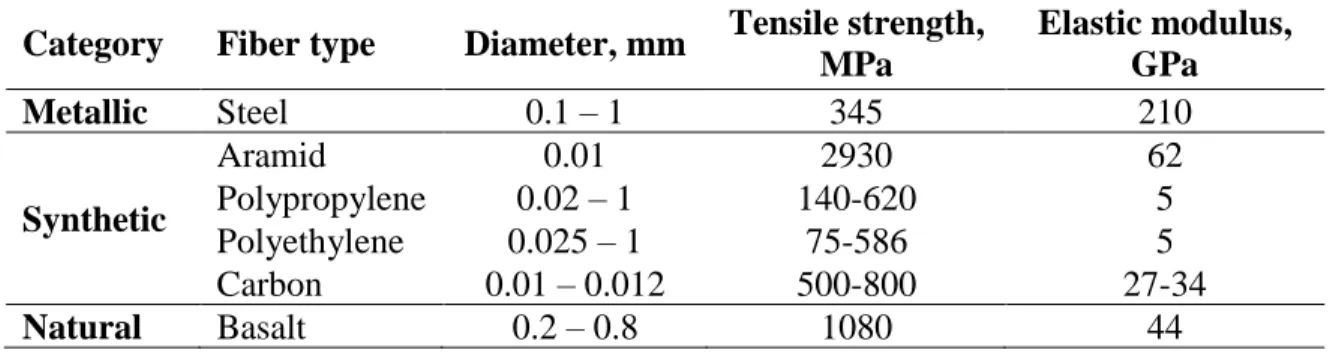
Table 1-1: Physical properties of fibers (extracted from ACI 544.1R-96) Category Fiber type Diameter, mm Tensile strength,
MPa Elastic modulus, GPa Metallic Steel 0.1 – 1 345 210 Synthetic Aramid 0.01 2930 62 Polypropylene 0.02 – 1 140-620 5 Polyethylene 0.025 – 1 75-586 5 Carbon 0.01 – 0.012 500-800 27-34 Natural Basalt 0.2 – 0.8 1080 44 1.2.1.1 Metallic fibers
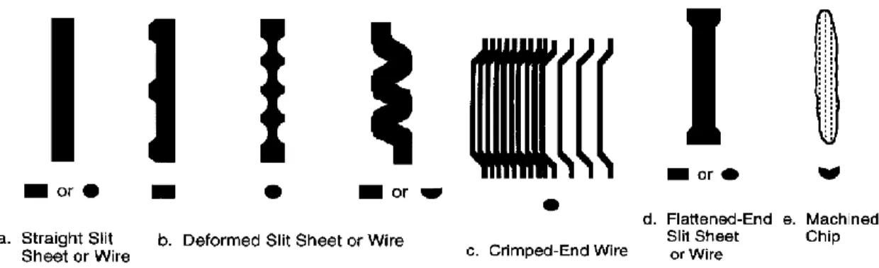
Steel fibers are the most common type of metallic fibers used in the concrete industry. As shown in Table 1-1, steel fibers are similar in mechanical properties to conventional steel bars. Steel fibers are available in various shapes and geometries. Their diameters vary between 0.10- and 1-mm. Steel fibers can be straight, end-hooked, crimped, and flattened-end as shown in Figure 1-1. Minelli and Plizzari (2013) reported that steel fiber-reinforced concrete (SFRC) exhibits enhanced deflection and pre-failure warning compared to that of normal concrete. Moreover, Kang et al. (2012) reported that steel fibers improved the durability, ductility, flexural toughness, impact resistance, and flexural strength of concrete. On the other hand, SFRC suffers corrosion and deterioration in an equivalent manner to conventionally-reinforced concrete when exposed to harsh chemical environments.
Figure 1-1: Various steel fibers shapes (adapted from Susetyo, 2011) 1.2.1.2 Synthetic fibers
Various materials are used in the fabrication of synthetic fibers such as: polyester, acrylic, aramid, carbon, polyethylene or polypropylene. Mu et al. (2002) stated the
6
importance of synthetic fiber-reinforced concrete (SNFRC) due to its non-corrosive nature, resistivity to alkaline attacks, durability, and its low cost. Therefore, SNFRC is considered appropriate to be used in aggressive chemical environments. Yazdanbakhsh et al. (2015) confirmed that synthetic fibers can be an acceptable alternative of reinforcement to limit shrinkage cracking and to enhance concrete toughness and load capacity. The mechanical properties of SNFRC can vary widely according to the material used, fiber geometry, fiber volume fraction, and the matrix composition.
Polypropylene fibers, shown in Figure 1-2, are the most widely-used synthetic fibers. Wang et al. (1987) reported that polypropylene fibers are available in a variety of cross-sectional shapes with different surface finishes, which allows further improvement in bond properties. Valle and Buyukozturk (1994) reported that polypropylene fibers are effective in controlling the propagation of micro-cracks in concrete and provide the concrete mix with ductility. Song et al. (2005) observed that the addition of polypropylene fibers to concrete improved its tensile and compressive strengths, its toughness, and its flexural properties.
Figure 1-2: Polypropylene fibers (Kalyani Polymers Private Limited © 1996-2018) 1.2.1.3 Natural fibers
Natural fibers were the primitive fibers to be used in reinforcing concrete. Natural fibers are classified into two types: organic and inorganic. Wood, cotton, hair, and wool are some examples of natural organic fibers. Inorganic natural fibers are mostly manufactured
7
from ingenious rocks such as Basalt and Asbestos. These types of fibers are characterized by their low cost and environmentally-friendly nature.
Basalt fibers are recently introduced to the market as discrete short fibers. They are characterized by their inert, non-corrosive, and non-toxic nature (Vajje et al. 2013). Basalt fibers are extracted from basalt rocks, which have high resistivity to alkaline and acidic attacks. Basalt fiber-reinforced concrete (BFRC) has been reported to have higher compressive strength, higher modulus of rupture, improved tensile properties, and higher flexural toughness than conventionally reinforced concrete (Kizilkanat et al. 2015 and Branston et al. 2016).
Basalt fibers come in the form of chopped fibers as shown in Figure 1-3a. Recently, macro fibers made of basalt and known as basalt MiniBarsTM were developed with an
enhanced performance than the chopped ones (ReforceTech report, 2013). MiniBarsTM
(Figure 1-3b) are distinguished over the regular chopped fibers with their performance that is similar to the basalt fiber-reinforced polymer (BFRP) bars but with smaller diameters and shorter lengths.
Ramakrishnan et al. (1998) reported that concrete mixed with MiniBarsTM have not encountered any problem of bleeding, segregation, or balling of fibers during mixing. On the contrary, it was reported that MiniBarsTM enhanced the workability of the mix. In addition, improvements in the post-cracking behavior and impact resistance were observed.
8
Figure 1-3: (a) Basalt chopped fibers (Branston et al., 2015) (b) Basalt MiniBarsTM (Ramakrishnan
et al., 1998) 1.2.2 Factors affecting the shear behavior of FRC
Fibers increase the shear strength of reinforced concrete members (Kwak et al., 2002). They play a significant role in resisting the formation of diagonal cracks and enhancing the ductility of the concrete members when added sufficiently to the concrete mix (Dinh, 2009). The random dispersion of fibers in concrete helps altering the cracking mechanism from macro cracking to micro cracking. This allows the formation of diagonal cracks with significantly reduced widths and provides concrete with more ductility and durability. The ACI 318-14 committee provides the acceptance criteria of fibers as minimum shear reinforcement, which considers the important influence of the fibers on the shear strength.
Several parameters contribute to the shear behavior of FRC including the fiber type and geometry, the fiber volume fraction, Vf, and the fiber aspect ratio,
𝐿𝑓
𝐷𝑓. These parameters are discussed in the following sub-sections.
1.2.2.1 Fiber geometry
Various shapes of fibers are commercially available. The most commonly-used are the straight, crimped, hooked-end, and indented fibers. The fabrication of different fiber shapes and geometries aims mainly at resisting the fiber pull-out from concrete. The friction between the fibers and the concrete mixture improves the shear load resistance as fibers slip out of concrete (Abbas et al. 2016). Deformed surfaces are believed to enhance the bond between fibers and concrete, decreasing the debonding and consequently the slippage of fibers (Kim et al. 2012). Concrete mix containing deformed-ends fibers were reported to have enhanced crack resistance while straight fibers were observed to enhance the workability of fresh concrete mix (Kang et al., 2011). Figure 1-4 shows the different shapes and sizes of steel fibers available in the industrial market.
9
Figure 1-4: Different geometries of steel fiber (Adopted from ACI 544.1R-96)
Abbas et al. (2016) stated that hooked-end fibers provided a better performance than straight fibers in terms of fiber pull-out resistance. Deep beams reinforced with hooked-end fibers exhibited an improvement in the pre-cracking behavior. On the other hand, their counterparts reinforced with straight round fibers, had a rather minor improvement.
Dylan (2016) studied the effect of steel fiber size and geometry on the mechanical properties of concrete. He reported that the size and shape of fibers had no effect on the compressive strength. However, long fibers contributed in bridging cracks and redistributing stresses than the short ones. In addition, the tensile strength was improved in specimens reinforced with long fibers compared to those reinforced with short fibers.
1.2.2.2 Fiber volume fraction
ACI 544.1-1R-96 defines the fiber volume fraction as the number of fibers added per unit volume of concrete mixture. The addition of steel fibers in sufficient quantities can enhance the shear strength of RC beams. The bridging and prevention of diagonal crack failure can alter the brittle shear failure into flexure failure. This was supported by Minelli and Plizzari (2013) as they reported that small fiber content improved the shear behavior of normal strength concrete (NSC) and high strength concrete (HSC). The study reported that fibers postponed the shear failure and transformed it to flexural failure with improved ductility. The increase in the fiber content increases the probability of bridging over the cracks and therefore enhances the ability of concrete to resist cracking (Iyer et al. 2015). However, high fiber contents could lead to the loss of concrete workability during mixing (Jianxun Ma et al. 2012).
10
Kwak et al. (2003) reported the improvement of shear strength of SFRC beams due to the addition of fibers at different quantities. The beams were cast using fiber volume fractions of Vf = 0, 0.5, and 0.75%. It was observed that high fiber contents had led to a
significant improvement in the shear capacity of the beams. An increase of 122 up to 180% in shear capacities was reported as the fiber content increased to 0.5 and 0.75% over the control beams. A notable decrease in cracks’ widths and a change in the failure mode were also observed.
Kang et al. (2012) studied the shear-flexure coupling behavior of 12 SFRC beams. The parameters investigated were the fiber volume fraction, Vf, the longitudinal
reinforcement ratio, , the type of concrete, and the shear-to-moment ratio. NSC and HSC beams were cast using Vf = 0, 0.375, 0.5 and 0.75% and = 1, 1.5 and 3%. The results showed
an increase in the compressive strengths of NSC and HSC with Vf = 0.75% by 17 and 10 %,
respectively. The addition of 0.5% of fibers increased the ultimate shear strength of NSC by 10% compared to that of the control beam. NSC beams with = 3% and Vf = 0.375%
experienced an increase in their shear strengths by 180% compared to their counterparts cast with no fibers. It was observed that the ductility increased by 30 and 200% at Vf = 0.5 and
0.75%, respectively, over the control beams. Steel fibers were noticed to provide HSC with a ductile mode of failure despite its brittle nature.
Jianxun Ma et al. (2012) reported that the high content of basalt fibers had a negative impact on the workability of freshly-mixed concrete. The fiber volume fractions used in the study were between 1 % to 3%. Test results showed that the fluidity of the concrete mix and the cubic compressive strength were inversely proportional to the added fiber content.
Patnaik et al. (2015) studied the effect of various volume fractions of basalt MiniBarsTM on the fresh and hardened concrete properties. The fiber content ranged from Vf
= 0.35 to 4%. The fresh concrete was observed to have no balling during mixing with an acceptable slump. Better mechanical properties were obtained with fiber dosage of Vf = 3%
as a 25% increase in its modulus was recorded compared to that of plain concrete. The addition of basalt fibers prevented the brittle failure of concrete cylinders tested under compression.
11
1.2.2.3 Fiber aspect ratio
Fiber aspect ratio is the main character that is used to describe fibers. It is defined as the ratio of the fiber length to its diameter, 𝐿𝑓
𝐷𝑓. Typical fiber aspect ratio ranges between 20 to 100. It is considered one of the main factors affecting the post-elastic property of concrete and the fiber bonding to concrete. High aspect ratios of fibers were found to be more efficient in enhancing the post-peak performance of concrete in SFRC and nylon fiber-reinforced concrete as reported by Iyer et al. (2015). Although the high aspect ratio of fibers is anticipated for better mechanical properties in hardened concrete, the potential of balling of fibers and loss of slump during fresh mixing increases. However, this can be avoided by retaining high pullout resistance by hooking the ends of fibers or roughening their surface (Abbas et al., 2016).
Iyer et al. (2015) studied the effect of different aspect ratios on the properties of BFRC beams. It was found that beams with high fiber aspect ratio exhibited a decrease in their workability during concrete mixing. The modulus of rupture of concrete was improved with the addition of fibers with high aspect ratio. The authors recommended the use of basalt fibers with a minimum length of 36 mm.
Abbas et al. (2016) studied the effect of different aspect ratios of fibers in SFRC slender and deep beams. The study showed that raising the aspect ratio from 60 to 100 increased the shear strength by 24 and 32% for slender beams and deep beams, respectively. This was due to the friction and bond strength induced between the fibers and the concrete surface. The fibers with higher aspect ratio provided the concrete with a better post-peak performance and an improved pre-failure warning.
1.2.3 Shear behavior of FRC
Voo et al. (2010) studied the shear strength of eight SFRC beams using ultra high-performance concrete (UHPC) with no stirrups. The factors considered in the test were the shape and geometry of fibers, volume fraction, Vf, and shear span-to-depth ratio,
𝑎 𝑑. The
results showed a direct relationship between the shear strength and the fiber volume fraction at the same shear span-to-depth ratio. The cracks propagated in the shear-span area then
12
multiplied towards the flange area leading to a single failure crack at peak load. The test results were analyzed using the plastic shear model and the variable engagement modeling PSM – VEM. The ratio of the predicted shear capacity to the experimental shear capacity Vpre/Vexp showed prominent level of accuracy with a value of 0.92 0.12, which indicates the
applicability of the PSM – VEM model for steel-reinforced UHPC.
Minelli and Plizzari (2013) studied the SFRC contribution to shear strength experimentally and analytically. The parameters considered in the test included the concrete strength, the reinforcement ratio, the fiber type, and the fiber volume fraction. Eighteen beams cast with NSC and HSC were cast using hooked-end and straight fibers with volume fraction ranging from 0.25 to 0.57%. The authors reported that the addition of fibers postponed the shear failure in both NSC and HSC beams and improved their ductility. Fibers enabled the formation of evenly distributed shear cracks instead of the propagation of a critical shear crack, which transformed the shear failure to flexural failure. Beams with low fiber volume fraction were able to resist twice the loading resisted by control beams.
Talboys and Lubell (2014) examined the shear behavior of six SFRC beams cast with high strength longitudinal steel bars. Hooked-end steel fibers were used with Vf = 1.0% and
fiber aspect ratio 𝐿𝑓
𝐷𝑓 = 55. It was observed that the beams with higher reinforcement ratio experienced more flexural stiffness. Indirect relationship was observed between the span-to-depth ratio and the ultimate load capacity.
1.3 Fiber-reinforced polymers (FRP)
Fiber-reinforced polymers (FRP) bars have witnessed a wide usage in the construction industry due to the corrosion problem associated with steel bars. FRPs are characterized by their high strength, light weight and low chemical reactivity in extreme environments (El Refai et al. 2015). Table 1-2 shows the mechanical properties of several types of FRP bars. FRPs have wide applications and are available in the market in several types such as carbon (CFRP), glass (GFRP), and aramid (AFRP). FRP bars are designed in many shapes to provide the utmost desired strength in different applications similar to steel bars (Figure 1-5).
13
Figure 1-5: FRP bars shapes (adopted from Cosenza et al., 1997) a) smooth b) ribbed c) indented d) braided e) grain-covered.
Table 1-2: Mechanical properties of steel and FRP bars according to ISIS-EC (2001).
Material Ultimate strength, MPa Elastic modulus, GPa
Steel 483 – 690 200
Glass 517 – 1207 30 – 55
Carbon 1200 – 2410 147 – 165
Aramid 1200 – 2068 50 – 74
* Basalt 1000 – 1200 45 – 50
*Basalt FRP values (El Refai and Abed, 2016).
1.3.1 Shear behavior of FRP-reinforced concrete beams
Yost et al. (2001) studied the shear behavior of beams reinforced with deformed GFRP bars. The beams had a span-to-depth ratio of 4 and various reinforcement ratios. It was observed that beams reinforced with GFRP and steel bars experienced a similar shear failure mode; however, the shear strength of GFRP-reinforced beams was much lower than their counterparts. The reinforcement ratio was observed to have negligible effect on the shear capacity. The results were compared to the predictions of the ACI 318-11 code and Deitz et al. (1999) model (Equation 1-1). The ACI 318-11 code overestimated the predicted shear strength while Deitz et al. (1999) equation had a reasonable estimation for the shear strength of GFRP reinforced beams.
𝑣𝑐 = 𝐸𝑓 𝐸𝑠 (1 6√𝑓𝑐 ′𝑏𝑑) (1-1)
14
Tureyen et al. (2003) examined the behavior of RC beams reinforced with FRP bars with no transverse reinforcement. Nine beams were reinforced with three types of FRP bars (two different GFRP bars and one type of AFRP bars) and two types of steel reinforcement. The parameters investigated were the type of reinforcement and the reinforcement ratio. The beams reinforced with FRP bars experimented lower shear strengths at failure compared to those of steel-reinforced beams of the same reinforcement ratio. The shear strength results were evaluated using the predictions of codes ACI 318-99 and ACI 440.1R-01. The provisions of ACI 318-99 overestimated the shear strength of FRP-reinforced beams while ACI 440.1R-01 provided conservative predictions.
Alam et al. (2013) evaluated the shear capacity of concrete beams reinforced with GFRP, CFRP, and steel bars. The beams had various span-to-depth ratios. The results showed that as the depths of the beams increased, the crack spacing increased while the shear strength at failure decreased. Both CSA-S806 and CSA-S6 codes accurately predicted the experimental shear strengths.
Mahmoud and El-Salakawy (2014) evaluated the concrete contribution to the shear behavior of six GFRP-reinforced continuous beams with minimum transverse reinforcement. The parameters studied were the type of reinforcement, the reinforcement ratio, concrete strengths (normal, NSC, and high strength, HSC), and the continuity. The results showed that the shear strength had a direct relationship with the concrete strength for GFRP-reinforced beams. The increase in reinforcement ratio had a negligible effect on the shear capacity of NSC beams. However, the shear capacity of HSC beams decreased with the increase of reinforcement ratio. All beams experienced a diagonal shear failure; yet, no sudden failure occurred after the formation of diagonal cracks. A moment and shear redistribution occurred, which resulted in a change in the shear failure position from interior to exterior span. The shear capacities were predicted using the provisions of CSA-S806-12, CSA-S6-06, and ACI 440.1R-06. The predictions of CSA-S806-12 were the most accurate of all provisions whereas the predictions of CSA-S6-06 and ACI 440.1R-06 were conservative.
15
1.3.2 Shear behavior of BFRP-Reinforced concrete beams
Issa et al. (2016) studied the shear behavior of BFRP-reinforced concrete beams with and without transverse reinforcement. The parameters investigated were the reinforcement ratio, shear span-to-depth ratio, and the beams. Beams with no stirrups and high reinforcement ratio were observed to exhibit a more brittle failure compared to beams with stirrups and lower reinforcement ratio. It was observed that the shear strength improved as the reinforcement ratio increased. High values of shear span-to-depth ratios caused a reduction in the shear strength of the tested beams.
El Refai and Abed (2016) investigated the concrete contribution to the shear behavior of 8 BFRP-reinforced beams. Two steel-reinforced beams were included in the test for experimental and analytical comparison purposes. The parameters investigated were the type of reinforcement, the reinforcement ratio from = 0.31 to 1.52%, and the shear span-to-depth ratio, 𝑎
𝑑 = 2.5 and 3.3. The BFRP-reinforced beams exhibited a diagonal tension mode of
failure similar to steel-reinforced beams. The shear strength was observed to decrease as the span-to-depth ratio increased. Higher strains were observed in both reinforcement and concrete as the 𝑎
𝑑 increased from 2.5 to 3.3. The ACI-440.1R-15, CAN/CSA-S806-12 and
CAN/CSA-S6-10 codes and the JSCE-97 guidelines were used to predict the behavior of the tested beams. CSA-S806-12 code gave precise predictions for the shear behavior of BFRP reinforced beams. The JSCE-97 guidelines slightly overestimated the shear strength of the beams while the ACI-440.1R-15 and CAN/CSA-S6-10 were found conservative.
Tomlinson and Fam (2014) studied the shear and flexural behavior of concrete beams reinforced with BFRP bars with and without stirrups. The parameters tested were the reinforcement ratios that ranged from ρ = 0.28 to 1.60% and the type of shear reinforcement. reinforced beams without stirrups failed in diagonal shear mode while BFRP-reinforced beams with BFRP stirrups exhibited rupture of stirrups. The ultimate shear strength was observed to increase as the reinforcement ratio increased. In addition, for the same reinforcement ratio, BFRP bars enhanced the shear strength of concrete by 2.6 to 2.9 times than steel-reinforced beams. The experimental results were compared to the predictions
16
of ACI 440.1R-06 and CSA S806-12 codes. ACI 440.1R-06 was too conservative in predicting the shear strength of BFRP-reinforced beams.
1.4 Shear design equations for FRP-reinforced concrete elements
Table 1-3 summarizes the design equations used to predict the shear behavior of FRP-reinforced members according to CAN/CSA-S806-12, CAN/CSA-S6-14, ACI-440.1R-15, and JSCE-97 codes.
17
Table 1-3: Shear Design Equations for FRP-reinforced concrete (MPa)
Code Shear Design Equations (MPa) Notes
CSA-S806-12 (2012) 𝑉𝑐= 0.05𝜑𝑐𝑘𝑚𝑘𝑟𝑘𝑎𝑘𝑠√𝑓′𝑐 3 𝑏𝑤𝑑𝑣 f’c 60 MPa and d 300 mm 𝑘𝑚= √ 𝑉𝑓𝑑 𝑀𝑓 ≤ 1.0 𝑘𝑟 = 1 + (𝜌𝑓∗ 𝐸𝑓)1/3 1.0 ≤ 𝑘𝑎= 2.5 𝑀𝑓 𝑉𝑓𝑑 ⁄ ≤ 2.5 𝑘𝑠= 750 450 + 𝑑 ≤ 1.0 CSA-S6-14 (2014) 𝑉𝑐 = 2.5 𝛽𝜑𝑐𝐹𝑐𝑟𝑏𝑤𝑑 𝐹𝑐𝑟 = 0.4 √𝑓𝑐′ ≯ 3.2 MPa 𝛽 = 230 1000 + 𝑆𝑧𝑒 𝑆𝑧𝑒= 35𝑆𝑧 15 + 𝑎𝑔 ≥ 0.85𝑆𝑧 ACI 440.1R-15 (2015) 𝑉𝑐 = 2 5𝑘√𝑓𝑐 ′𝑏 𝑤𝑑 𝑘 = √(𝑛𝜌)2+ 2𝑛𝜌 − 𝑛𝜌 JSCE-97 (1997) 𝑉𝑐= 𝛽𝑑𝛽𝑝𝛽𝑛𝑓𝑣𝑐𝑑 𝛾𝑏 𝑏𝑤𝑑 b = 1.3 and n = 1
if no axial forces are applied to the member 𝛽𝑝= ( 100𝜌𝐸 𝐸𝑠 ) 0.25 ≤ 1.5 𝛽𝑑= ( 1000 𝑑 ) 0.25 𝛽𝑛= 1 + 𝑀𝑜 𝑀𝑑 ≤ 2, for N’d ≥ 0 𝛽𝑛= 1 + 2 𝑀𝑜 𝑀𝑑 ≥ 0 , for N’d < 0 𝑓𝑣𝑐𝑑 = 0.2 ( 𝑓𝑐′ 𝛾𝑐) 0.333 ≤ 0.72 MPa
Vf = factored shear force (kN), Mf = factored moment (kN.m), bw = width of the beam (mm), d = depth of the beam (mm), dv is the greater of 0.72 h or 0.9 d, f = longitudinal reinforcement ratio, Ef = modulus of elasticity of FRP bars (GPa), 𝜑c = concrete reduction factor, n = modular ratio, b = strength reduction factor, n = factor
accounting for axial forces, Mo = decompression moment, Md = design bending moment, N’d = design axial
18
1.4.1 CSA-S806-12 (2012) equations
Equations 1-2 to 1-7 of CSA-S806-12 predict the concrete contribution to the shear strength of FRP-reinforced elements having compressive strength f’c 60 MPa and effective
depth, d, 300 mm. 𝑉𝑐 = 0.05𝜑𝑐𝑘𝑚𝑘𝑟𝑘𝑎𝑘𝑠√𝑓′𝑐 3 𝑏𝑤𝑑𝑣 (1-2) where; 𝑘𝑚= √ 𝑉𝑓𝑑 𝑀𝑓 ≤ 1.0 (1-3) 𝑘𝑟 = 1 + (𝜌𝑓∗ 𝐸𝑓)1/3 (1-4) 1.0 ≤ 𝑘𝑎 = 2.5 𝑀𝑓 𝑉𝑓𝑑 ≤ 2.5 (1-5) 𝑘𝑠 = 750 450 + 𝑑 ≤ 1.0 (1-6)
Vc is limited to the following boundaries:
0.11𝜑𝑐√𝑓𝑐′ 𝑏𝑤𝑑𝑣 Vc 𝑉𝑟𝑚𝑎𝑥 = 0.22φ𝑐 𝑓𝑐′𝑏𝑤𝑑𝑣 (1-7)
1.4.2 CSA-S6-14 (2014) equations
According to CSA-S6-14 (2014), equations 1-8 to 1-12 are used to predict the concrete contribution to the shear strength of FRP-reinforced elements.
𝑉𝑐 = 2.5 𝛽𝜑𝑐𝐹𝑐𝑟𝑏𝑤𝑑 (1-8)
where
19
For sections without transverse reinforcement and with maximum aggregate size not less than 20 mm, is calculated as following:
𝛽 = 230 1000 + 𝑑𝑣
(1-10)
For sections without transverse reinforcement and for all aggregate sizes:
𝛽 = 230 1000 + 𝑆𝑧𝑒 (1-11) 𝑆𝑧𝑒 = 35𝑆𝑧 15 + 𝑎𝑔 ≥ 0.85𝑆𝑧 (1-12) 1.4.3 ACI 440.1R-15 (2015) equations
ACI 2015 adopted the results of Tureyen and Frosch (2013) to derive equations 1-13 and 1-14 to predict the shear behavior of FRP-reinforced members.
𝑉𝑐 = 2
5𝑘√𝑓𝑐′𝑏𝑤𝑑
(1-13)
where
𝑘 = √(𝑛𝜌)2 + 2𝑛𝜌 − 𝑛𝜌 (1-14)
n = modular ratio and 𝜌 = longitudinal reinforcement ratio.
1.4.4 JSCE-97 (1997) equations
The Japanese design guidelines recommend equations 1-15 to 1-20 to calculate the concrete contribution, 𝑉𝑐, of FRP-reinforced concrete members. As can be observed from the equations, JSCE-97 does not account for the shear span-to-depth ratio and neglects the concrete contribution to the shear strength in case of plain concrete or no added longitudinal reinforcement (i.e. Vc = 0 at ρ = 0 %).
Vc = βdβpβnfvcd γb bwd
(1-15)
20 βp = (100ρE Es ) 0.25 ≤ 1.5 (1-16) βd = (1000 d ) 0.25 (1-17) 𝛽𝑛 = 1 +𝑀𝑜 𝑀𝑑 ≤ 2, for N’d ≥ 0 (1-18) 𝛽𝑛 = 1 + 2 𝑀𝑜 𝑀𝑑 ≥ 0 , for N’d < 0 (1-19) and fvcd = 0.2 ( fc′ γc) 0.333 ≤ 0.72 MPa (1-20)
b is a strength reduction factor = 1.3 (taken as 1 in this study) and n is the axial force factor
(taken as 1 if no axial forces are applied to the member as in this study).
1.5 Shear design equations proposed for FRC
Different models were proposed to predict the contribution of FRC to the shear strength. Some of these models were based on experimental data while others were based on empirical assumptions. The contribution of fibers in concrete to its shear strength is defined according to several parameters such as the aspect ratio, the fiber volume fraction, and the span-to-depth ratio.
Most of the available models were initially developed to predict the shear capacities of SFRC-reinforced elements with longitudinal steel bars except that of Gopinath et al. (2016), which was developed to predict the shear capacities of SFRC beams having longitudinal reinforcement made of BFRP, and that of Abbadi (2018) that predicts the shear capacities of BFRP-reinforced beams cast with basalt fiber-reinforced concrete (BFRC). The following section presents the equations of different models that will be used later in predicting the shear capacities of the beams tested in this study.
21
Table 1-4: Models predicting shear strength for FRC (MPa)
Model Shear strength Equations (MPa) Notes
Narayanan & Darwish (1987) 𝑣𝑢= 𝑒(0.24𝑓𝑠𝑝+ 80𝜌 𝑑 𝑎) + 𝑣𝑏 𝑒 = 1 , if 𝑎𝑑> 2.8 𝑒 = 2.8𝑑 𝑎 , if 𝑎𝑑≤ 2.8 𝑓𝑠𝑝= 𝑓𝑐𝑢𝑓 (20−√𝐹)+0.7+1.0√𝐹 𝑓𝑐𝑢𝑓 = 1.2 𝑓′𝑐 𝑣𝑏= 0.41𝐹 𝐹 = (𝐿𝑓 𝐷𝑓) 𝑉𝑓𝑑𝑓 Ashour et al. – A (Zsutty’s formula) (1992) 𝑣𝑢= (2.11√𝑓3 ′𝑐+ 7𝐹)(√𝜌 𝑑 𝑎 3 ) 𝑎 𝑑> 2.5 𝑎 𝑑≤ 2.5 𝑣𝑢= (2.11√𝑓′𝑐 3 + 7𝐹)(√𝜌𝑑 𝑎 3 )(2.5𝑑𝑎) + 0.41τ𝐹(2.5 −𝑎𝑑) Ashour et al. – B
(Modified ACI eq.) (1992) 𝑣𝑢= (0.7√𝑓
′ 𝑐+ 7𝐹) 𝑑 𝑎+ 17.2𝜌 𝑑 𝑎 Shin et al. (1994) 𝑣𝑢 = 0.19𝑓𝑠𝑝+ 93𝜌 ( 𝑑 𝑎) + 0.834𝑣𝑏 Kwak et al. (2002) 𝑣𝑢= 3.7𝑒𝑓𝑠𝑝2⁄3(𝜌𝑑 𝑎) + 0.8𝑣𝑏 Gopinath et al. (2016) 𝑣𝑐 = (( 𝛽𝑑𝛽𝑝𝛽𝑛𝑓𝑣𝑐𝑑 𝛾𝑏 ) + ((2.11√𝑓𝑐 ′ 3 + 7𝐹) (√𝜌𝑑 𝑎 3 )) ) 0.91 Abbadi (2018) 𝑉𝑐 = ((0.05λ𝜑𝑐𝑘𝑚𝑘𝑟𝑘𝑎𝑘𝑠3√𝑓′𝑐𝑏𝑤𝑑𝑣) + (0.19𝑓𝑠𝑝+ 93𝜌 (𝑑 𝑎) + 0.834𝑣𝑏) 𝑏𝑤𝑑𝑣) 0.85
𝑓𝑐𝑢𝑓= cube strength of fibers concrete = 1.2𝑓𝑐′ MPa, a = shear span, mm), 𝑣𝑏 = fiber pullout stress, 𝜏 is the interface bond matrix = 4.15 MPa as recommended by Narayanan and Darwish (1987), F = fiber factor, 𝐿𝑓 = length of fibers (mm), 𝐷𝑓 = diameter of fibers (mm), 𝑉𝑓 = volume fraction of fibers, df = fiber bond factor ( 1 for hooked-end and indented fibers, 0.75 for crimped fibers and 0.5 for round fibers.
22
1.5.1 Narayanan and Darwish (1987)
Narayanan and Darwish (1987) recommended the following equation to calculate the shear strength of SFRC beams reinforced longitudinally with steel bars:
𝑣𝑢 = 𝑒(0.24𝑓𝑠𝑝+ 80𝜌𝑑
𝑎) + 𝑣𝑏
(1-21) where fsp is the splitting tensile strength of concrete given as,
𝑓𝑠𝑝 = 𝑓𝑐𝑢𝑓
(20 − √𝐹) + 0.7 + 1.0√𝐹
(1-22)
e is a constant taken as,
Either; 𝑒 = 1 , if 𝑎 𝑑> 2.8 or, 𝑒 = 2.8𝑑 𝑎 , if 𝑎 𝑑 ≤ 2.8
vb is the fiber pullout stress calculated as,
𝑣𝑏= 0.41𝐹 (1-23)
and F is the fiber factor:
𝐹 = (𝐿𝑓
𝐷𝑓) 𝑉𝑓𝑑𝑓
(1-24)
1.5.2 Ashour et al. model – A (1992)
Ashour et al. (1992) proposed a model based on Zsutty’s formula to predict the shear strength of high-strength SFRC beams reinforced longitudinally with steel bars:
For beams with 𝑎
𝑑 > 2.5 𝑣𝑢 = (2.11√𝑓3 ′𝑐 + 7𝐹)( √𝜌 𝑑 𝑎 3 ) (1-25)
and for beams with 𝑎
𝑑≤ 2.5 𝑣𝑢 = (2.11√𝑓3 ′𝑐 + 7𝐹)( √𝜌 𝑑 𝑎 3 )(2.5𝑑 𝑎) + 0.41τ𝐹(2.5 − 𝑎 𝑑) (1-26)
23
1.5.3 Ashour et al. model – B (1992)
This equation was developed by modifying the ACI shear formula (ACI 318R-89) to incorporate the effect of shear span-to-depth ratio. Using regression analysis, the following equation was proposed.
𝑣𝑢 = (0.7√𝑓′ 𝑐 + 7𝐹) 𝑑 𝑎+ 17.2𝜌 𝑑 𝑎 (1-27)
1.5.4 Shin et al. model (1994)
The following equation was proposed by shin et al. (1994) to predict the shear strength of high strength SFRC beams reinforced longitudinally with steel bars. Test parameters included the volumetric ratio of steel fibers, the shear-span-to-depth ratio, the amount of longitudinal reinforcement, and the amount of shear reinforcement. The model considers the splitting tensile strength of concrete, fsp, the dowel action, 𝜌
𝑑
𝑎, and the pull-out
strength of fibers, vb.
𝑣𝑢 = 0.19𝑓𝑠𝑝+ 93𝜌 (𝑑
𝑎) + 0.834𝑣𝑏
(1-28)
1.5.5 Kwak et al. model (2002)
Kwak et al. (2002) tested 12 steel-reinforced beams with steel fibers using different fiber volume fractions. The test results were combined with a database of 139 beams investigated by previous researchers. Kwak et al. (2002) proposed the following equation to evaluate the shear strength of SFRC beams reinforced longitudinally with steel bars.
𝑣𝑢 = 3.7𝑒𝑓𝑠𝑝2⁄3(𝜌𝑑
𝑎) + 0.8𝑣𝑏
(1-29)
1.5.6 Gopinath et al. model (2016)
Gopinath et al. (2016) studied the analytical and experimental shear behavior of SFRC beams reinforced with BFRP bars. Test results showed that JSCE-97 accurately predicted the shear strength of the beams without steel fibers while the model of Ashour et al. – A (1992) gave reasonable predictions for the beams. Gopinath et al. (2016) proposed a
24
new model to predict the shear strength of SFRC beams reinforced with BFRP bars. The model combined the equations of JSCE-97 and Ashour et al. (1992) – A as follows:
𝑣𝑐 = (( 𝛽𝑑𝛽𝑝𝛽𝑛𝑓𝑣𝑐𝑑 𝛾𝑏 ) + ((2.11√𝑓𝑐 ′ 3 + 7𝐹) (√𝜌𝑑 𝑎 3 )) ) 0.91 (1-30)
JSCE -97 equation Ashour et al. (1992) model – A
1.5.7 Abbadi’s equation (2018)
Abbadi (2018) developed an equation to predict the shear behavior of basalt fiber-reinforced lightweight concrete members (BFLWC) fiber-reinforced longitudinally with BFRP bars. The suggested equation combined the equation of CSA-S806-12 code and that of Shin et al. (1994) model. Abbadi (2018) modified the equations to account for the light weight aggregates used in concrete by incorporating the coefficient as given in equation 1-31.
𝑉𝑐 = ((0.05λ𝜑𝑐𝑘𝑚𝑘𝑟𝑘𝑎𝑘𝑠√𝑓′𝑐 3 𝑏𝑤𝑑𝑣) + (0.19𝑓𝑠𝑝 + 93𝜌 𝑑 𝑎+ 0.834𝑣𝑏) 𝑏𝑤𝑑𝑣) 0.85 (1-31)
CSA-S806-12 equation Shin et al. (1994) equation
In the study, it was recommended that the bond factor, df, used in calculating the fiber
factor F taken as 0.75 for basalt fibers rather than 1.0 when hooked-end steel fibers are used. In the absence of experimental tests on the basalt fibers, the interface bond matrix factor = 4.15 was used in calculating the fiber pull-out strength, vb, as recommended by Narayanan
25
1.6 Concluding remarks from the literature review
The following points summarize the outcomes of the literature review:
• The addition of fibers to concrete improves the post-cracking behavior as the crack widths decrease. Fibers also increase the shear strength of FRC members and emphasize a ductile manner compared to normal concrete.
• The type and geometry of fibers have a significant effect on the shear behavior of FRC elements. They also affect the bonding and the pull-out strength of fibers upon cracking.
• The reinforcement ratio and the shear span-to-depth ratio are important parameters that influence the shear behavior of FRC beams.
• There is a lack of studies on the behavior of FRC structures reinforced with FRP bars, not to mention those cast with BFRC. The applicability of the available analytical models has never been assessed to predict the shear performance of such structures.
• The previously proposed models and code formulations lack the consideration of the type of longitudinal reinforcement in predicting the shear capacity of RC structures. The equations were proposed based on the experimental results of steel-reinforced beams and only consider the reinforcement ratio of longitudinal steel bars.
• Limited studies have evaluated the shear contribution of basalt fibers as alternative to the conventionally used steel fibers. The hybrid reinforcement of basalt fibers, as additives to the concrete mix, and BFRP bars, as longitudinal reinforcement, has rarely been investigated.
26
1.7 Objectives of the current study
Based on the conducted literature review, the main objective of the current study is to investigate the shear performance of BFRP-reinforced beams cast with basalt MinibarsTM with no transverse reinforcement added. Other objectives include:
• Investigate the effect of various parameters such as the reinforcement ratio of the longitudinal BFRP bars, the fiber volume fraction of basalt fibers, and the shear span-to-depth ratio of the specimens on the shear behavior of the hybrid system BFRC – BFRP.
• Assess the applicability of different shear design formulations to evaluate the shear contribution of BFRC – BFRP elements.
27
Chapter 2: Experimental program
2.1 ScopeThe experimental program consisted of fourteen BFRC beams reinforced with BFRP bars. The beams were divided into two groups of two different shear span-to-depth ratios and each group has different fiber volume fractions and reinforcement ratios. The beams were cast with different reinforcement ratios, ρ, shear span-to-depth ratios, 𝑎
𝑑, and fiber volume
fractions, 𝑉𝑓. Seven BFRP-reinforced beams were adopted from a previous study conducted by El Refai and Abed (2016) to act as control beams.
The test program and the investigated parameters are detailed in the following sections. In addition, the description of the test specimen, material properties, test setup, and the test procedure are discussed.
2.2 Test program and investigated parameters
Table 2-1 summarizes the experimental test program. The specimens were cast in the labs of Qatar university and tested under four-point loading configuration. The beams were divided into two groups (A and B) according to their 𝑎
𝑑 ratio that ranged between 3.3 and 2.5
for groups A and B, respectively. Group A included fifteen beams reinforced longitudinally with BFRP bars with five different reinforcement ratios, chosen as multiples of the balanced reinforcement ratio, ρb, (1.09, 1.69, 2.43, 3.69, and 5.35 ρb). Group B had six beams
reinforced with BFRP bars at reinforcement ratios of 1.09 and 2.43 ρb. In both groups, and
for each reinforcement ratio, two fiber volume fractions (0.75 and 1.5%) were used to cast the beams. The balanced reinforcement ratio, ρb, was calculated according to
ACI-440.1R-15 as follows: 𝜌𝑏 = 0.85𝛽1 𝑓𝑐′ 𝑓𝑓𝑢 𝐸𝑓𝜀𝑐𝑢 𝐸𝑓𝜀𝑐𝑢+ 𝑓𝑓𝑢 (2-1)
where β1 = ratio of depth of equivalent rectangular stress block to depth of the neutral
axis; 𝑓𝑐′ = concrete compressive strength; 𝑓
𝑓𝑢 = ultimate strength of the BFRP bar; 𝐸𝑓 =
28
The beams are labeled as follows: the first letter refers to the beam group (A or B), the next letters refer to the reinforcement ratio from R1 to R5 while the last digits refer to the volume fraction of the added fibers. For instance, beam A-R2-0.75 refers to a beam in group A that was cast with reinforcement ratio of 1.69 ρb (R2) and fiber volume fraction of 𝑉𝑓 =
0.75%.
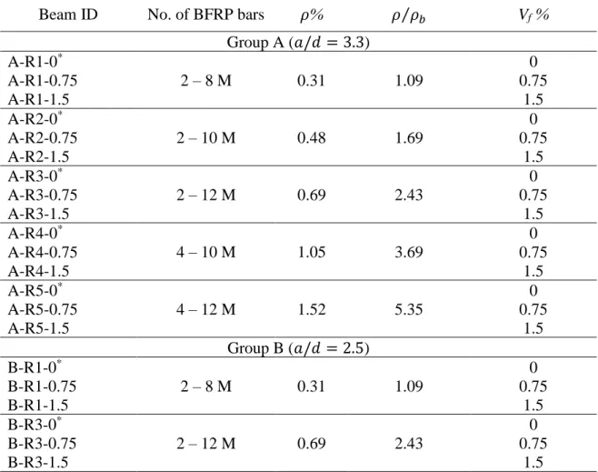
Table 2-1: Test matrix
Beam ID No. of BFRP bars 𝜌% 𝜌 𝜌⁄ 𝑏 Vf %
Group A (𝑎/𝑑 = 3.3) A-R1-0* 2 – 8 M 0.31 1.09 0 A-R1-0.75 0.75 A-R1-1.5 1.5 A-R2-0* 2 – 10 M 0.48 1.69 0 A-R2-0.75 0.75 A-R2-1.5 1.5 A-R3-0* 2 – 12 M 0.69 2.43 0 A-R3-0.75 0.75 A-R3-1.5 1.5 A-R4-0* 4 – 10 M 1.05 3.69 0 A-R4-0.75 0.75 A-R4-1.5 1.5 A-R5-0* 4 – 12 M 1.52 5.35 0 A-R5-0.75 0.75 A-R5-1.5 1.5 Group B (𝑎/𝑑 = 2.5) B-R1-0* 2 – 8 M 0.31 1.09 0 B-R1-0.75 0.75 B-R1-1.5 1.5 B-R3-0* 2 – 12 M 0.69 2.43 0 B-R3-0.75 0.75 B-R3-1.5 1.5
*Beams reported from El Refai and Abed (2016)
2.3 Test specimens
All beams were 2 meters long with a rectangular cross section of 254 mm high and 152 mm wide. The beams were reinforced longitudinally with BFRP bars without any transverse reinforcement. BFRP bars were located at the tension face of the beams and arranged either in one or two layers according to the reinforcement ratio as shown in Figure 2-1. All beams were cast with a clear cover of 30 mm.
29
Figure 2-1: Specimens details (all dimensions are in mm) 2.4 Material properties
2.4.1 Concrete
Two concrete batches of different fiber volume fractions were used in casting the test
beams. The detailed mix design is shown in Table 2-2. To determine the effect of different fiber dosages on the 28-day compressive strength of concrete, five standard cylinders (150 mm in diameter and 300 mm in height) were cast for both batches. The cylinders were subjected to the same curing conditions as those of the beams.
Table 2-2: Concrete mix design
Type Quantity (kg/𝑚3) Cement 440 Fly ash 50 Water 149.6 Coarse aggregates 1158 Fine aggregates 752 Super plasticizer 8.8
30
2.4.2 BFRP bars
Sand-coated BFRP bars of nominal diameters of 8, 10, and 12 mm were used as longitudinal reinforcement for the beams. The mechanical properties of the bars were adopted from a previous study conducted by El Refai and Abed (2016). The reported nominal tensile strength of BFRP bars was 1168 MPa with an elastic modulus of 50 GPa and elongation at ultimate of 0.023. A linear stress-strain relationship described the behavior of the BFRP bars in tension up to failure. Figure 2-2 shows the various sizes of BFRP bars used in this study.
Figure 2-2: Different sizes of BFRP bars used in this study (El Refai and Abed, 2016) 2.4.3 Basalt MiniBarsTM
MiniBarsTM, shown in Figure 2-3, are macrofibers which are considered a
scaled-down version of BFRP bars. They are known for their helix shape and rough surface, which enhances their bond to concrete. The MiniBarsTM used in this study had a dimeter, 𝐷𝑓, of 0.66 mm and cut length, 𝐿𝑓, of 43 mm, which is equivalent to an aspect ratio, 𝐿𝑓
𝐷𝑓, of 65.15. The fibers have a tensile strength of 1100 MPa, modulus of elasticity 60 GPa, with a specific density of 1.9 g/cm³ as reported in the manufacturer’s datasheet. It is worth mentioning that the specific density of MiniBarsTM is close to that of concrete, which minimizes the possibility of balling during mixing (Adhikari, 2013).
31
Figure 2-3: Basalt MiniBarsTM length in mm. and inches (Reforcetech report, 2013).
2.5 Beam instrumentation and fabrication
All BFRP bars were instrumented with strain gauges bonded at their mid-span as shown in Figure 2-4. The surface of BFRP bar was first ground using an electrical grinder. Then, the strain gauges were glued to the surface using a chemical adhesive. Finally, the top surface of the gauges was protected from debris using an insulation cover.
Figure 2-4: Installation of strain gauges to BFRP bars
Cages and wooden forms were assembled before casting the concrete. Plastic chairs were placed all over the sides of the wooden form to ensure a uniform clear height of 30 mm (Figure 2-5).
Concrete mixing and casting were done according to the ASTM-C192 guidelines. Firstly, one-third of the water quantity were mixed with fine and coarse aggregate. After that, the remaining quantity of water was added with cement and fly ashes, then mixed for two additional minutes. Finally, the required fiber dosage was added, and mixing continued for three minutes to ensure the homogeneity of the mix. After casting, the top surface of the beams was manually finished using flat steel trowels. The beams were overlaid by wet
32
burlaps and kept in their wooden formwork for two days. After dismantling the forms, the curing continued for 28 days.
Figure 2-5: Casting of beams 2.6 Test setup
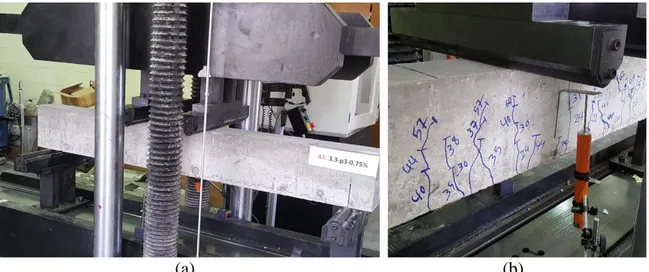
The tested beams were simply-supported and tested under four-point loading configuration (Fig. 2-6). The load was applied in displacement control at a rate of 2 mm/min using a hydraulic jack at two points spaced 600 mm until failure occurred. A linear variable differential transducer (LVDT) was placed at the soffit of the beam to measure the variation in deflection while loading. Concrete strains were measured using a 60-mm-long strain gauge placed at mid-span on the top surface of concrete. Data from strain gauges and LVDTs were recorded using a 30-channel data acquisition system at a rate of 5 readings/s.
33
(a) (b)
34
Chapter 3: Experimental results
3.1 IntroductionThis section presents the test results. The effect of fibers on the mechanical properties of concrete is firstly presented. The results of the four-point test conducted on the tested beams were then presented. Comparisons between different beams in terms of their shear capacities, strains in the longitudinal BFRP bars and concrete, load-deflection relationships, and failure modes are discussed to examine the effect of each investigated parameter on the behavior of the tested beams.
3.2 Material test results
The effect of various dosages of basalt MiniBarsTM on the mechanical properties of concrete is presented in this section. For each concrete batch, five standard concrete cylinders (150 x 300 mm) were cast and tested to determine the relationship between the fiber volume fraction, Vf, and the compressive strength of concrete, 𝑓′𝑐. The cylinders were cured for 28
days, before being kept at room temperature until the day of testing. It is worth mentioning that both the cylinders and the beams were subjected to identical curing conditions. Before testing, the cylinders top surface was mechanically grinded to eliminate any debris that might affect the results. The compression tests were performed with accordance to the guidelines provided by ASTM-C469. The average compressive strength, 𝑓′𝑐, standard deviation, SD, and coefficient of variance, COV, for each concrete batch are shown in Table 3-1. The compressive strength, 𝑓′𝑐, of specimens with no fibers was 49 MPa as reported in El Refai and Abed (2016).