HAL Id: hal-01004689
https://hal.archives-ouvertes.fr/hal-01004689
Submitted on 5 Nov 2016
HAL is a multi-disciplinary open access archive for the deposit and dissemination of sci-entific research documents, whether they are pub-lished or not. The documents may come from teaching and research institutions in France or abroad, or from public or private research centers.
L’archive ouverte pluridisciplinaire HAL, est destinée au dépôt et à la diffusion de documents scientifiques de niveau recherche, publiés ou non, émanant des établissements d’enseignement et de recherche français ou étrangers, des laboratoires publics ou privés.
Theoretical and numerical limitations for the simulation
of crack propagation in natural rubber components
Pierre Charrier, Elisabeth Ostoja-Kuczynski, Erwan Verron, Gilles
Marckmann, Laurent Gornet, Grégory Chagnon
To cite this version:
Pierre Charrier, Elisabeth Ostoja-Kuczynski, Erwan Verron, Gilles Marckmann, Laurent Gornet, et al.. Theoretical and numerical limitations for the simulation of crack propagation in natural rubber components. 3rd European Conference on Constitutive Models for Rubber (ECCMR), Sep 2003, Londres, United Kingdom. �hal-01004689�
1 INTRODUCTION
In the past, Rivlin & Thomas (1953) proposed an efficient criterion for elastomeric material strength characterisation. This was especially needed by chemical departments to compare their recipes for the development of new compounds.
The authors considered an energetic failure crite-rion: the tearing energy T. This approach can be seen as the extension of Griffith (1920) theory to rubber-like materials. The corresponding crack propagation criterion can be written as:
(
)
c ext T A W W T ≥ ∂ − ∂ = , (1)where Tc is the critical value of the tearing energy at
the failure point; W the stored elastic energy; Wext
the work of external forces and A is the area. Under constant displacement loading conditions, the work of external forces is equal to zero and the previous equation reduces to:
c l T c W t T ≥ ∂ ∂ − = 1 (2)
where t stands for the thickness of the sample and c for the crack length.
Lake & Lindley (1965) suggested extending the use of T to cyclic loading. They proposed a general model for the Crack Growth Curve (CGC) that links
the crack growth rate dc/dn to the cyclic load, here
the maximum tearing energy Tmax endured by the
sample, is given by: α max T B dn dc = ⋅ (3)
where B and α are the parameters of the law.
For forty years, two main research approaches have been investigated to estimate the duration life of rubber components. The former one consists in defining standard procedures to compare and clas-sify compounds in laboratory. The main purpose of this approach is to limit the number of experiments performed on real components, because their cost and duration time are not compatible with the actual design loops of automotive industries (Charrier et al. 2003b). Major difficulties arise to reproduce real service conditions (mechanical, thermal, chemical and ageing conditions) due to their complexity. For example, Summer & Kelbch (1995) recently devel-oped an adapted procedure to tire applications.
The later approach focus on crack propagation simulation using the Finite Element Method. Indeed, fatigue characterization of elastomers being an es-sential prerequisite of new car project schedules, du-rability prediction softwares are needed to reduce design duration of elastomeric parts.
The present paper deals with this second method. After a brief analysis of theoretical limitations asso-ciated with the use of the tearing energy theory, we
Theoretical and numerical limitations for the simulation of crack
propagation in natural rubber components
P. Charrier, E. Ostoja-Kuczynski
Modyn Trelleborg Zone ind. de Carquefou, BP 419, 44474 Carquefou Cedex - France
E. Verron, G. Marckmann, L. Gornet, G. Chagnon
Ecole Centrale de Nantes, Institut de Recherche en Génie Civil et Mécanique, BP 92101, 44321 Nantes Cedex 3 - France
ABSTRACT: In this paper, two commercial software packages dedicated to the simulation of crack propaga-tion in elastomer components were tested: FLEXPAC and MSC-MARC. Firstly, the theoretical limitapropaga-tions of classical crack propagation laws were examined to demonstrate that actual numerical predictions are limited to very simple loading conditions. Secondly, crack propagation approaches implemented in both softwares were analysed. In order to compare their performances, fatigue experiments are performed. Different rubber components with different pre-cracks were tested under several loading conditions. Crack propagation, i.e. size and direction of the crack, was measured as a function of the number of cycles. Then, these results were compared with crack direction criteria proposed by the two models. It was demonstrated that loading ampli-tude highly influenced the crack direction and that the models must take this into account in their solver. Fi-nally, limitations of this type of numerical analysis to predict the duration life of rubber components were highlighted.
will propose a benchmark of FLEXPAC and MSC-MARC, two commercial software packages dedi-cated to crack propagation in industrial rubber parts. 2 THEORETICAL LIMITATIONS OF THE
TEARING ENERGY APPROACH 2.1 Industrial context
Tire manufacturers have studied the durability of elastomers for more than 60 years. Numerous papers examined the definition of a well-adapted criterion for this type of industrial application: the tearing en-ergy. Moreover, a large experimental database is available, but most experiments are restricted to plane stress test samples under simple loading con-ditions.
Automotive Anti-Vibration System (AVS) com-panies are also interested in the durability of elasto-mers. However, the corresponding industrial com-ponents and loading conditions are very different than those involved in the tire industry. Indeed, loading states are close to plane strain, and loading histories are complex: they include variable pre-loading, non-relaxing conditions… Consequently, in order to investigate the durability of elastomers in AVS applications, it is necessary to determine the limitations of the tearing energy criterion to ensure that its use is well-adapted in these conditions. 2.2 Mode I / III and thickness effect
Classical failure mechanisms distinguishes three main crack opening modes based on relative motion of crack faces (classically, I is the opening mode, II stands for the plane shear mode and III represents the anti-plane shear mode).
For elastomeric components, most of experimen-tal characterizations are performed using thin sam-ples of rubber , i.e. in plane stress conditions (see for example Gent et al. 1964); it is often concluded that the Crack Growth Curve (CGC) does not depend on sample geometry (in fact, these conclusions are re-stricted to pure shear specimens, tensile strips, and trousers). In several papers, authors demonstrated that the CGC is an intrinsic characteristic and can be used for thick test samples (Lindley & Stevenson (1982), Lindley & Teo (1979), Charrier et al. (2003b), De & Gent (1998), and Aboutorabi et al. (1998)).
Using these results, one can states that “whatever the loading conditions are, the CGC corresponding to mode I can be used”. However, some other results refute this statement. For example, Gent & Henry (1967) exhibited a ratio of 2 between critical tearing
energies TC measured with a pure shear and a trouser
samples. The second specimen was previously modified to enforce the crack direction, and the knotty tearing was probably prevented. A similar
explanation could be invoked to understand the strange results obtained by South et al. (2002). More recently, Legorju-Jago & Bathias (2002) showed that the crack growth rate decreases as the thickness of the sample increases.
Remark: the CGC obtained with simple extension experiments can not be used in every loading cases. 2.3 Pre-loading effect
2.3.1 Uniaxial loading
Classically, three different types of uniaxial cyclic loading are considered.
2.3.1.1 Relaxing loading
At the end of every cycle, the applied load returns to 0. This is typically the case for tires but not for AVS components due to the existence of a constant static pre-loading (e.g. the engine weight). Moreover, it should be noted that there is an important difference between enforced force and enforced displacement loading conditions. In fact, during experiments, the stiffness decreases due to two phenomena: the structural modulus of the sample decreases when crack grows and a viscoelastic response takes place (cyclic creep or relaxation). As shown in Figure 1, under enforced displacement, the maximum load evolves from point 1 (initial) to point 2’ (viscoelas-ticity) and point 3’ (crack growth). As the available tearing energy decreases, the crack growth rate de-creases too. It is exactly the opposite under enforced force: crack propagation accelerates.
Remark: experimentally, it is obvious that the crack grows more rapidly under enforced force than under enforced displacement conditions. Neverthe-less, one can not affirm that it is only due to the de-crease of the sample stiffness or if viscous effects should be considered.
2.3.1.2 Tensile – compressive loading
During the compressive part of cycles, a phe-nomenon similar to the crack closure effect of me-tallic parts takes place. A simple parameter could be used to superimpose all CGC measured with load
F ∆l 1 2' 2'' 3' 3'' Viscous effect Geometric effect
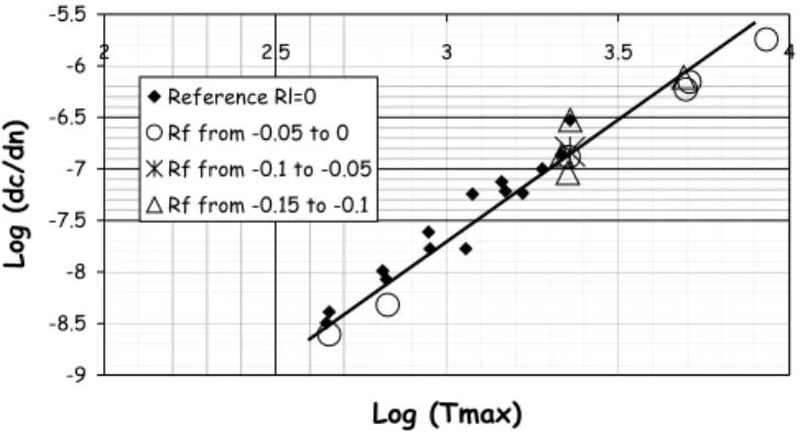
Figure 1. Evolution of sample stiffness during cyclic relaxing experiment. -9 -8.5 -8 -7.5 -7 -6.5 -6 -5.5 2 2.5 3 3.5 4 Log (Tmax) Log (dc/ dn) Reference Rl=0 Rf from -0.05 to 0 Rf from -0.1 to -0.05 Rf from -0.15 to -0.1
Figure 2. Crack growth curve measured with DSS (Double Simple Shear) sample. The displacement is enforced and the reference is obtained with relaxing conditions Rl = Lmin/Lmax =
0. The tensile compressive loading results are superimposed to the reference curve.
ratios RF lower or equal to 0 (see Figure 2):
max
T T =
∆ (4)
where ∆T represents the efficient part of the
loading cycle and RF is defined as:
max min F F F R = (5)
2.3.1.3 Tensile – tensile loading
Lindley (1973) showed that as the tearing
energy-ratio RT becomes positive, the crack growth
resis-tance is highly improved.
max min T T T R = (6)
This is due to the occurrence of a new phenome-non: “cyclic branching” or “cyclic knotty tearing” (see for example photos of Busse (1934)). Even
small deviations from 0 of the loading ratio RT lead
to an important decrease of the crack growth rate (see Figure 3).
Well-adapted models were recently proposed to overcome this difficulty. Charrier et al. (2002,
2003a) showed that RT must be considered to
char-acterise the increase of the crack growth resistance.
( )
R B ∆Tα g dn dc T ⋅ ⋅ = (7)where g is a function of the tearing energy-ratio and
∆T is the effective-part of the load: ) 0 , max( min max T T T = − ∆ (8)
Charrier et al. (2003a) considered the following function (see Figure 4):
( )
( )
R 1 forR 0 g 0 R for ) R exp( R g 1000 T T 000 . 1 T 1000 T T < = ≥ × = β (9)where RT1.000 stands for the tearing energy ratio that
corresponds with 1000 cycles.
-9 -8.5 -8 -7.5 -7 -6.5 -6 -5.5 2 2.5 3 3.5 4 Log (∆T) Log (dc/dn) Reference Rl=0 "RT from 0 to 0.02" "RT from 0.02 to 0.035" "RT from 0.05 to 0.07" "RT from 0.09 to 0.11"
Figure 3. Crack growth curve measured on DSS (Double Sim-ple Shear) samSim-ple. The displacement is enforced and different CGC are obtained for different values of RT.
1.E-03 1.E-02 1.E-01 1.E+00 1.E+01 0.00 0.05 0.10 0.15 RT Normalised dc/dn DT = 2 200 J/m² DT = 5 000 J/m² DT = 9 000 J/m²
Figure 4. Identification of the g(RT).
Moreover, the type of loading is as important as in the case of relaxing loading conditions. However, in the present case, enforced displacement condi-tions are more critical than enforced force loadings. Indeed, for enforced displacement, the curve 1-2 is transformed into 1’-2’ in Figure 5 due to crack growth and viscous effects, the maximal available tearing energy and the tearing energy ratio decrease. In regard with these observations, the crack should
slow down, but dueto the evolution of RT , it
accel-erates.
Remark: as in relaxing conditions case, we can not affirm that viscous effects could be neglected. In that case, a mean stress correction should be pro-posed to simplify the characterisation of elastomers behaviour. F ∆l 1 1' 2' 1'' 2'' 2
Figure 5. Evolution of the sample stiffness during cyclic ten-sile / tenten-sile experiments.
2.3.2 Multiaxial loading
Dealing with industrial components, endurance specifications often includes multiaxial loading con-ditions associated with a pre-loading in a given di-rection (e.g. engine weight in the vertical didi-rection and vibrations in the three directions of space).
Gent & Kim (1978) studied the influence of a pre-loading parallel to the crack (maintained or not
during experiments) on Tc the critical tearing energy.
Only filled natural rubbers are influenced by a non-maintained pre-load parallel to the crack. In the other hand, all compound types are weakened when the pre-loading is maintained. This effect is ampli-fied by strain-induced crystallisation.
The same kind of experiments was conducted on filled NR by Busfield et al (1996) under cyclic con-ditions. Opposite to the static cases, non-maintained pre-loading parallel to the crack, i.e. accommoda-tion, does not influence the duration life. But once again, under maintained pre-load the strength dra-matically decreases.
As the anisotropic mechanisms that take place close to the crack front are not well understood, it is obvious that the evolution of the mechanical proper-ties of elastomeric materials under cyclic loading should be predicted using simulation softwares.
Remark: the crack propagation in elastomers un-der multiaxial loading conditions remains an open problem.
2.4 Others effects
According to different authors (see for example Charrier et al., 2002), NR is not a really temperature dependent material in its design range (0 – 80 °C), especially for its durability properties. However, this conclusion must be restricted to the cases where the heat build-up is limited. In other cases, some new mechanisms could lead to the failure of the compo-nent.
Moreover, Summer & Kelbch (1995) obtained different CGC using two types of signal: the sinu-soidal and the pulsed signals. It is a serious difficulty that CGC depends on the form of the signal. So this observation leads to an interesting question: what kind of signal should be used during CGC measure-ment, in order to be able to estimate the crack growth rate using Road Load Data (RLD)? More generally, what parameters are missing in the crack propagation law to account for this phenomenon?
In conclusion of this part, it can be stated that a general model for the crack growth rate in elasto-mers is not currently available to take into account non relaxing conditions, multiaxiality and changes of the signal form.
3 NUMERICAL SIMULATION OF CRACK PROPAGATION – BENCHMARK OF COMMERCIAL SOFWARES
Using the Finite Element Analysis, the analytical fracture mechanics can be generalised to any com-ponent. However, it is sometimes difficult to obtain robust FEA solutions (surface contact, non-linear properties …), but fracture mechanics has been suc-cessfully used for Automotive rubber components design for many years (see for example Oh (1980)).
Two commercial software packages are currently available to model crack propagation. The first one is FLEXPAC. It is developed by Mechanics Soft-ware Inc. and the Materials Engineering Research Laboratory Ltd. It is a complete Finite Element Software that includes three main modules: a mate-rial database, a FE solver for rubber components, and a fatigue calculator. The pre- and post-processor is ANSYS. The classical hyperelastic constitutive equations are available and FLEXPAC includes more specific development such as stress-softening models to consider cyclic relaxation. Moreover, the software does not support 2D plane stress analysis and the user must use quadratic elements. Crack propagation in 3D models is also possible with FLEXPAC. In all cases, the crack front is divided into segments in which different values of the tear-ing energy are calculated. Some simple experimental validation of FLEXPAC have already been proposed by Harris et al. (2000), Stevenson et al. (1999) and more recently Yeoh (2001).
The second software tested in the present study is MSC-MARC. It includes a module devoted to the crack propagation in elastomers. In this context, all elements and constitutive equations can be used. However, simulations are limited to 2D plane strains and axisymmetric problems. According to the authors, the present paper is the first that deals with this tool.
3.1 Methods employed for crack growth prediction in commercial softwares
3.1.1 FLEXPAC
This a two-steps approach. First, the user meshes the cracked component with ANSYS, chooses a maxi-mum load level and performs an FE simulation with FLEXPAC. The tearing energy is calculated, by the use of the virtual crack extension method (VCEM) for several intermediate loading levels, and the crack propagation direction is predicted for the maximum loading. Then, using this direction and considering a new crack increment, the user meshes again the component. At the end of the process, the evolution of T along the crack trajectory was computed for different loading levels Fi:
(
c,Fi)
T (10)
Second, the user defines a loading level Fapplied,
an increment of cycles ∆n and the initial size of the
crack c0. Then, the post-processor calculates the
crack growth curve (CGC) of the component:
( )
=∫
=∫
c(
(
)
)
c applied N 0 0 f T c,F dc dnc c N (11)This method, that consists in distinguishing the FE simulation and the fatigue estimation, can be used to perform optimisation studies. Indeed, with only one series of FE simulations, several fatigue predictions could be performed by changing the load level and the initial flaw size. However, the assump-tion which states that there is no relaassump-tionship be-tween the loading level and the trajectory of the crack should be validated. In the case of components that include several cracks, this separation is not possible. So, the crack length increment for each new mesh depends on the tearing energy calculated for each crack front.
According to FLEXPAC, the crack will
propa-gate in the direction in which T is maximum, and in
that case the CGC obtained with simple experiments can be used to simulate real components. Pidaparti & Pontula (1995) proposed a similar assumption that was validated more recently by Busfield et al. (1999) with pure shear samples. However, the pres-ent method is very time consuming. In order to re-duce computing time, another assumption has been proposed. It states that the crack will grow in the di-rection where the maximum principal stress is maximum. It is equivalent to the first assumption presented above (see for example Van Zelst et al. 2002).
3.1.2 MSC-MARC
The method implemented in MSC-MARC is fully automated. The user meshes the component without crack, and defines the crack localisation, the loading conditions (multiaxial loading conditions are ac-cepted), the size of the re-meshed zone close to the
crack front and the crack length increment ∆c. Then,
the component is automatically re-meshed including the crack and a special circular mesh in the neigh-bourhood of it as shown in Figure 6.
Figure 6. A mesh used by MSC-MARC.
In MSC-MARC, the tearing energy is calculated by the J-integral method. As shown by Busfield et al. (1999), it is equivalent to the energy balance and the
crack tip closure methods. So, the evolution of T is
computed along the loading cycle in order to evalu-ate the maximum applied tearing energy. The crack is supposed to grow in the direction of the maximum
tangential stress σθθ when T is maximum, and the
corresponding increment of cycles is determined using a relaxing CGC. Afterwards, the component is automatically re-meshed taking into account the crack growth increment. The simulation ends when the distance between the crack and boundaries of the components (or between two cracks) is lower than a given threshold value.
Using this method, there is no assumption on the effect of the loading level on the crack direction. Moreover, the time spent by the user to mesh the component is highly reduced and, as a consequence, the total duration for a complete study decreases from several hours to several minutes.
Modelling small cracks (lower than 1 mm) is dif-ficult however, due to the automatic remeshing pro-cedure. So, it is not easy to estimate the duration life
of a component that contains a small default (size c0
< 0.05 mm). Moreover, the study of adhesive failure is not possible, so that cracking must be cohesive. 3.2 Experimental results
In order to compare numerical results with industrial cases, two NR engine mounts were chosen. The first one, shown in Figure 7, is axisymmetric and verti-cally loaded under tensile / compressive conditions. The initial crack is circular and located close to the internal insert. The second engine mount, shown in Figure 8, is sufficiently thick to adopt the plane strain assumption. It is loaded horizontally under relaxing conditions. An initial pre-crack was created far from this insert.
Initial pre-crack localisation
Figure 7. Axisymmetric engine mount with a circular pre-crack.
Initial pre-crack localisation
Figure 8. Plane strain engine mount. 3.3 Numerical results
3.3.1 Comparison with experiments
In the axisymmetric engine mount, the crack propa-gation is unstable: at the end of the experiment, the engine mount is cut and it reveals that the crack does not remain axisymmetric. Figure 9 presents the crack length as a function of the number of cycles. Vertical error bars reflects the scattering of crack length around the symmetry axis. Thus, it is difficult to define the CGC.
Numerical simulations were not able to accu-rately predict the crack direction. Indeed, during ex-periments, the crack direction remains parallel to the insert and the fracture is cohesive at approximately 1 mm from the insert. However, in the simulation, the crack direction changes rapidly and the crack tends to reach the insert, as shown in Figure 10 for MSC-MARC results. A similar behaviour was ob-tained with FLEXPAC.
Due to these experimental and numerical diffi-culties, the study of the axisymmetric engine mount was stopped. Through the rest of the paper, we only focus on the plane strain engine mount. Experimen-tal and numerical results are compared in Figures 11 and 12. It yields to the following commentaries:
0 5 10 15 20 25
0.E+00 2.E+05 4.E+05 6.E+05 8.E+05
Number of cycles
Total crack length (mm)
c = f(N) c0 = 2 mm
Figure 9. Experimental CGC for the axisymmetric engine mount.
Figure 10. Crack trajectory predicted by MSC-MARC for the axisymmetric engine mount.
− using MSC-MARC, numerical results are in good agreement with experimental data in the case of enforced force,
− for enforced displacement, the crack propagation predicted by MSC-MARC is slower than the propagation under enforced force, but not suffi-ciently to agree well with experiments in which viscous effects stop the propagation before reaching the insert,
− even if crack growth rates are very different for enforced displacement and force loading condi-tions, both lead to the same crack direction as ob-served experimentally,
− at the beginning of the propagation under en-forced displacements, the crack growth rate ob-tained by FLEXPAC is smaller than the one computed with MSC-MARC. Afterwards, the crack growth rates are similar. At our opinion, this discrepancy is due to the methods employed by softwares: FLEXPAC seems to calculate the Tearing Energy that corresponds with a straight propagation even when the crack turns. As
pro-posed by Busfield et al. (1999), T should be
cal-culated in the crack direction in which it is maximum.
3.3.2 Influence of some parameters
In order to investigate more precisely capabilities of the models. The influence of the initial crack ori-entation and size, and of the loading level were ex-amined. 0 2 4 6 8 10 12 14 16 18 20 0 20 000 40 000 60 000 80 000 100 000 Number of cycles
Total crack length (mm)
Test results
MSC_MARC enforced force MSC_MARC enforced displacement FLEXPAC enforced displacement
Figure 11. Experimental, MSC-Marc and FLEXPAC CGC.
MSC MARC - Enforced Force MSC MARC - Enforced Discplacement
Approximative measured crack trajectory
Figure 12. Crack trajectories predicted by MSC-MARC for horizontal pre-crack.
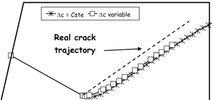
Dc fixe Dc adaptatif
Real crack trajectory
∆c = Cste ∆c variable
Figure 13. Crack trajectories predicted by MSC-MARC for an inclined pre-crack.
First, simulations with different initial crack ori-entations were performed. The corresponding results are shown and compared to experiments in Figure 13. When the initial pre-crack direction highly dif-fers from the experimental crack trajectory, both softwares cannot predict satisfactorily the rapid crack upturn. Even the adaptive crack length incre-ments proposed by MSC-MARC are not sufficient to solve this problem. Nevertheless, after a short propagation, predicted and experimental cracks are parallel.
Second, the influence of the size of the initial
pre-crack c0 is considered. As proposed by Greensmith
(1964), and Lake & Lindley (1964), the duration life can be estimated using a crack propagation approach and considering that the size of the initial default corresponds to the mean size of defects in rubber. Figure 14 shows the results of some simulations with different pre-crack sizes The main conclusion
is that c0 has a great influence on the duration life
calculation. Moreover its intrinsic nature is doubtful. Third, the influence of the loading level on the crack trajectory is examined. Crack trajectories ob-tained with different levels by MSC-MARC are pre-sented and compared to an experimental curve in Figure 15. Note that FLEXPAC results are similar. Numerically, the upturn becomes more important as the loading level increases. It confirms our experi-mental observations. Moreover, we can conclude that the two-step method employed by FLEXPAC
0 5 10 15 20 25
0.0E+00 5.0E+05 1.0E+06 1.5E+06
Numbre of cycles total cr ack le ngth (m m ) Co = 0.3mmCo = 0.5mm Co = 1mm Co = 2mm Co = 3mm
Figure 14. Influence of the size of the initial default on the du-ration life predicted by FLEXPAC.
1250 N 850 N 750 N 250 N
Real crack trajectory Fmax = 900 N
Figure 15. Influence of the loading level on crack propagation. should be used very carefully: finite element simulations and duration life predictions are con-ducted separately, but they must be performed with
the same loading level (see the term Fapplied in
Equa-tion 11).
4 CONCLUSION
In conclusion, two questions have to be asked. Can the engineer use this kind of software during the de-sign of new components? If yes, what type of infor-mation will he obtain? As the size of natural defects in rubber is not well-known, these software pack-ages can not predict the duration life of the compo-nents. In fact, a crack initiation theory (Wöhler curve) should be preferred at the beginning of a new AVS project. Nevertheless, for a given existing part that breaks down during durability experiments, the models can be used to improve the component ge-ometry in order to reduce the crack growth rate.
In our opinion, some progress is needed to gener-alise the use of this type of software in industry. First, a large effort on numerical methods must be made: the robustness of the method should be im-proved, and a 3D adaptive mesh refinement proce-dure must be developed. Second, crack growth rate laws must be improved to include the effects of pre-loading, multiaxiality and viscoelasticity. Third, ac-curate behaviour laws for elastomer must be taken into account in order to improve the predictions. 5 REFERENCES
Aboutorabi N., Ebbot T. Gent A. N. & Yeoh O.H. 1998. Crack Growth in Twisted Rubber Disk. Part I: Fracture Energy Calculations. Rubber Chem. Technol. 77: 76-83.
Busfield J.J.C., Davises C.K.L & Thomas A.G. 1996. Aspects of Fracture in Rubber Components., Proc. Int. Rubber Conf.: 191-207. Manchester
Busfield J.J.C., Ratsimba C.H.H. & Thomas A.G. 1999. Crack growth and predicting failure under complex loading in filled elastomers. In Boast D, Coveney V.A. (eds), Finite Element Analysis of Elastomers, Prof. Eng. Pub. Ltd, Lon-don.
Busse W.F. 1934. Tear Resistance and Structure of Rubber, Ind. Eng. Chem.: 1194-1199.
Charrier P., Ostoja-Kuczynski E., Verron E., Gornet L. & Chagnon G. 2002. Influence of loading conditions on fa-tigue properties for filled elastomers International Rubber Conference; Proc. intern. symp., 1-4 Jully 2002. Prague: Czech Republic.
Charrier P., Ostoja-Kuczynski E., Verron E., Gornet L. & Chagnon G. 2003a. Use of Finite element Method for crack propagation prediction in rubber material under cyclic loading – State of the art and perspectives. (in prep.) Charrier P., Ostoja-Kuczynski E., Verron E., Gornet L. &
Chagnon G. 2003b. Double Simple Shear test sample (DSS): a new procedure to characterise cyclic crack growth properties of rubber-like material. (in prep.)
De D. K. & Gent A. N. 1998. Crack Growth in Twisted Rub-ber Disk. Part II: Experimental Results, RubRub-ber Chem. Technol 77: 84-93.
Gent A. N., Lindley P. B. & Thomas A. G. 1964. Cut Growth and Fatigue of Rubbers. I. Relationship between Cut Growth and Fatigue J. Appl. Polym. Sci. 8: 455-466. Gent A.N. and Henry A.W. 1967. On the Strength of Rubbers.
Proc. Int. Rubber Conf. 5th Brighton: 193-204. London. Gent A. N. & Kim H. J. 1978. Tear Strength of Streched
Rub-ber, Rubber Chem. Technol. 51: 35-44.
Greensmith H.W. 1964. Rupture of Rubber XI. Tensile rupture and Crack growth in a Noncrystallizing Rubber. J. Appl. Polym. Sci. 8: 1113-1128.
Griffith A. 1920. The Phenomena of Rupture and Flow in Solids. Phil. Trans. Roy. Soc., 221(A): 163-199.
Harris J.A., Hawkes J.R., Campion R.P. & Derham C.J. 2000. Advances and Challenges in Longterm Service Life Pre-diction of Elastomeric Engineering Components. Rubber Division Meeting, American Chemical Society, 4-6 April 2000. Dallas Texas
Lake G.J. & Lindley P.B. 1964. Cut Growth and Fatigue of Rubbers. II. Experiments on Noncrystallizing Rubber. J. Appl. Polym. Sci. 8: 707-721.
Lake G.J. & Lindley P.B. 1965. The Mechanical Fatigue Limit for Rubber. J. Appl. Polym. Sci. 9: 1266-1251
Legorju-Jago K. & Bathias C. 2002 Fatigue Initiation and Propagation in Natural and Synthetic Rubbers. Int. Journ. Fat. 24: 85-92
Lindley P. B. 1973. Relation between hysteresis and the dy-namic crack growth resistance of Natural Rubber. Int. J. Fract. 9: 449-462.
Lindley P. B. &Teo S. C. 1979. Energy for crack growth at the bonds of Rubber Springs. Plastics and Rubber : Material and Applications: 29-37.
Lindley P. B. & Stevenson A. 1982. Fatigue resistance of Natural Rubber in compression. Rubber Chem. Technol. 5: 337-351.
Oh L.H.L. 1980. A fatigue-life model of rubber bushing. Rub-ber Chem. Technol. 53: 1226-1238.
Pidaparti R.M.V & Pontula G. 1995. Fracture analysis of cracked rubber components in two and three dimensions. Theor. Appl. Frac. Mech. 22: 1-8.
Rivlin R. S. & Thomas A. G. 1953. Rupture of Rubber. I. Characteristic Energy for Tearing. J. Polym. Sci 10: 291-318.
South J.T., Case S.W. & Reifsnider K.L. 2002 Crack growth of Natural Rubber using a Modified Double Cantiveler Beam. Mech. Mater. 34: 451-458.
Stevenson A., Hawkes J.R., Harris J.A. & Hansen P. 1999. Fa-tigue Life of Elastomeric Engineering Components under Biaxial Loading using Finite Element Analysis. Engineer-ing Integrity. 5: 8-19.
Summer A.J.M. & Kelbch S.A..1995. Crack Growth Perform-ance of Tire Compounds. Rubber World November: 38-45. Van Zelst A., Lechtenböhmer A. & Schreurs D. 2002.
Endur-ance Prediction of Farm Tire Lugs, Euromech Colloquium 438 July 15 – 17 2002. Vienna
Yeoh O.H. 2001 Analysis of deformation and fracture of “Pure Shear” rubber testpiece. Plastics, Rubber and Composites. 30(8): 389-397.