O
pen
A
rchive
T
OULOUSE
A
rchive
O
uverte (
OATAO
)
OATAO is an open access repository that collects the work of Toulouse researchers and makes it freely available over the web where possible.This is an author-deposited version published in : http://oatao.univ-toulouse.fr/ Eprints ID : 4749
To link to this article : DOI :10.4028/www.scientific.net/MSF.636-637.485
URL : http://dx.doi.org/ 10.4028/www.scientific.net/MSF.636-637.485
To cite this version : Ngnekou, P.E.T. and Lafont,
Marie-Christine and Senocq, François and Lacaze, Jacques and Viguier, Bernard ( 2010)Short Term Oxidation of a Ti-46Al-8Nb Alloy at
700°C in Air. Materials Science Forum, vol. 636-637 . pp. 485-490.
ISSN 0255-5476
Any correspondance concerning this service should be sent to the repository administrator: [email protected].
Short Term Oxidation of a Ti-46Al-8Nb Alloy at 700°C in Air
P.E.T. Ngnekou
a, M.C. Lafont
b, F. Senocq
c, J. Lacaze
dand B. Viguier
eUniversité de Toulouse, CIRIMAT, ENSIACET, 118 Route de Narbonne, 31077 Toulouse, France a
[email protected]; [email protected];
cfranç[email protected]; d[email protected]; e[email protected]
Keywords: Titanium aluminides based on TiAl, Oxidation, Rutile, Amorphous oxide.
Abstract. Thermogravimetry was used to study the oxidation behaviour of a lamellar Ti46Al8Nb alloy during holding at 700°C in synthetic air. A parabolic plot of the oxidation kinetics shows three different regimes over the total duration (50 h) of the tests corresponding to decreasing values of the parabolic rate constant. The oxide scale was characterized by glancing-angle X-Ray diffraction and transmission electron microscopy. The scale was found to be bi-layered with an outer part that consists of amorphous aluminium rich oxide whilst the inner layer is made of very small cristalites of titania distributed in the same amorphous oxide.
Introduction
Owing to their low density and good mechanical properties, TiAl-based intermetallics have been considered to have a high potential for applications as structural materials at intermediate and high temperatures. Their oxidation resistance above 800°C is, however, a concern but this resistance may be improved by alloying, e.g. with niobium. In their pioneering work, Choudhury et al. [1] noticed that TiAl is an alumina former when oxidized in oxygen and titania former when oxidised in air, at 950°C. Later, Meier et al. [2] stressed the very peculiar oxidation behaviour of binary Al-rich TiAl alloys that form a continuous alumina layer in air at high temperature (1100-1350°C) and in oxygen at much lower temperature (800°C), but do not form such a continuous alumina layer at high temperature in oxygen.
Since then, the so-called nitrogen effect associated to oxidation under air has been extensively studied as reviewed by Brady et al. [3]. According to Rakowski et al. [4], oxidation of a Ti-50Al (at. %) alloy at 800-900°C in air leads to a scale of intermixed Al2O3 and TiN grains after 1 h. These
TiN precipitates transform to TiO2 with further oxidation while new TiN precipitates appear at the
metal/scale interface. The scale becomes layered with an outer TiO2 layer and an inner layer made
of TiO2 and Al2O3. Within the inner layer, the concentration of alumina is higher close to the outer
layer. The same scale structure was found by Locci et al. [5] after long-term (9000 h) oxidation of Ti-48Al-2Cr-2Nb at 704°C in air. At higher temperatures, Taniguchi and Shibata [6] observed a similar layered oxide although there was no TiN. These authors also reported that when TiAl is alloyed, the alloying elements may form specific oxides that precipitate close to the substrate/oxide interface [6].
Because of this limited oxidation resistance associated with the nitrogen effect, present applications of TiAl alloys are foreseen for intermediate temperatures, in the 600 to 800°C range. However, even short-time exposure to oxygen at such intermediate temperatures leads to dramatic alloy embrittlement, the possible mechanisms of which have been discussed by Thomas et al. [7]. This suggested studying the very first stages of oxidation at a temperature representative of possible service temperatures, namely 700°C.
Experimental details
Small parallelepiped-shape specimens (10x10x1 mm3) were machined from a cylindrical rod 20 mm in diameter and 70 mm in length provided by the Interdisciplinary Research Centre (IRC) in Materials for High Performance Applications (Birmingham U.K.). The composition of the alloy is
Ti-45.1Al-8.5Nb (at. %). The specimens were polished using SiC papers up to the grade 4000, then carefully washed in an ultrasonic bath containing acetone. Isothermal oxidation experiments were conducted in a SETARAM TAG24 thermo-balance, which has a precision of 1 g. For reproducibility checking, two specimens were successively submitted to the same oxidation test. After placing the coupon in the TGA cell, the reaction and reference tubes were flushed with argon and then filled with synthetic air (20% O2 and 80% N2). The gas flow rate was then kept constant to
about 0.4 L.h-1 during the tests for continuous renewal of the oxidizing environment. The specimens were brought to 700°C by continuous heating at a rate of 1°C.s-1. The weight change was recorded every 30 seconds in the first experiment and every 15 seconds in the second. After 50 h, the specimens were allowed to cool down to room temperature at a rate of 1°C.s-1 and were then removed for X-Ray and TEM analysis.
XRD data were collected in glancing incidence configuration on a Seifert XRD 3000TT apparatus fitted with a diffracted beam graphite monochromator. CuK radiation was used in the
present study. TEM observations of the thin oxide layer were performed using a JEOL JEM 2010 microscope at the “Toulouse Paul Sabatier University Temscan Service”. This TEM operates at 200 kV and is equipped with a TRACOR EDX spectrometer. Cross-sections of the oxide layer were prepared by cutting the specimens into thin slices (in a direction normal to the oxide/substrate interface) with a diamond wire saw. Two such slices were then glued together, oxide to oxide, and embedded in a 3mm diameter brass tube with epoxy resin. After curing, the tube was sectioned into approximately 300m thick discs that were then polished on both sides and dimpled before ion-milling to transparency with a low angle (0-10°) GATAN precision ion-beam polishing system (PIPS).
Results
The results of the isothermal oxidation experiments are shown in Fig. 1, where the square of the mass gain per unit area (∆m/A)2 is plotted as a function of time for linearity testing that would correspond to diffusion-controlled oxidation kinetics. Both curves present exactly the same features, and the final mass gains are very similar. At the very beginning of the experiments and up to about 30 min, the mass gain increases very rapidly, as previously observed by Lidong Teng et al. [8] for the same alloy. These authors considered this initial oxidation stage to be a chemical reaction controlled stage at the surface of the material. They noticed that its duration increases from 150 s at 1200°C to 600s at 900°C. The present results confirm this tendency with a much longer reaction period of about 1800 s at 700°C. After this initial period, the mass-gain curves present three consecutive linear domains, labelled 1, 2, and 3 in Fig. 1, with a gradual reduction of the slope. This behaviour shows that oxidation kinetics at 700°C certainly follow three different parabolic-like regimes in the first 50 h, after a very short initial transient stage. It is worth noting that the slope changes occur exactly at the same time in both experiments underscoring their reproducibility. The mass gains corresponding to those transitions are slightly different, mainly because of different mass gains during the initial transition stage.
Figure 1. Isothermal oxidation curves of the Ti-46Al-8Nb alloy at 700°C for 50 h. The square of the mass gain per unit area, (∆m/A)2
, is plotted as a function of time.
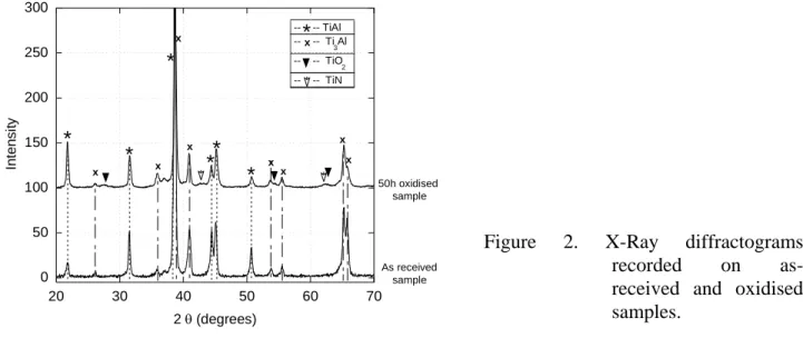
Glancing-angle (4°) X-Ray diffraction was carried out before and after oxidation. The records are compared in Fig. 2, on which mainly appear the peaks related to the phases 2-Ti3Al and -TiAl
of the substrate. However, upon close examination, some additional faint peaks can be observed. One peak at 2 = 36.97° appears on both records and is thus not related to the oxidation experiment. Several peaks also appear on the oxidized sample: i) three peaks at 2and 62.75° that could be indexed according to the lines of the rutile; and ii) two peaks at 2 and corresponding to titanium nitride. It should therefore be stressed that no peak of any form of crystalline alumina (eta, gamma, theta or alpha) could be identified in the diffractogram.
-- -- TiAl -- -- Ti 3Al -- -- TiO 2 -- -- TiN *x 0 50 100 150 200 250 300 20 30 40 50 60 70 In te n s it y 2 (degrees) * * ** * x x x x x x x 50h oxidised sample As received sample * x
Figure 2. X-Ray diffractograms recorded on as-received and oxidised samples.
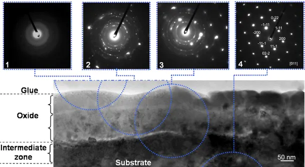
Fig. 3 shows a TEM image of the oxidized specimen surface and four diffraction patterns (labelled 1 to 4) corresponding to various selected areas using a 250 nm selected area aperture. For each of the patterns, the actual position of the aperture was superimposed on the image with a dotted circle. The scale appears bi-layered, with the outer and inner layers being, respectively, about 100 nm and 150 nm thick. The surface of the substrate in contact with the scale has a composition that differs from the bulk material; this is called the intermediate zone, as described below in Fig. 3.
Figure 3. Cross section TEM bright field image of the oxide scale and diffraction patterns (labelled 1 to 4) from four different locations indicated with dotted circles.
The diffraction pattern #1 shows no spots, meaning that the outer layer of the oxide scale is amorphous. Pattern #2 was obtained selecting an area containing both layers of the scale and shows multiple ring-like spots indicating the presence of fine crystals in the inner layer. These rings could be indexed according to the tetragonal rutile TiO2 with the a=b=0.45933 nm and c=0.29592 nm
lattice parameters [9] using the CaRine Crystallography software [10]. As with pattern #1, no trace of crystallised alumina could be found in this figure. Pattern #3 shows a superposition of the ring-like spots obtained from the inner scale and the spots of the -TiAl phase. Finally, the area selected for pattern #4 gives only spots corresponding to -TiAl.
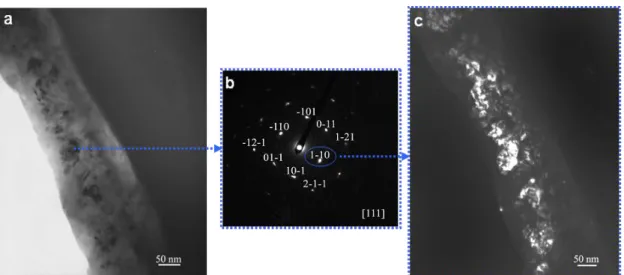
In Fig. 3, the internal layer of the scale shows many dark crystallites which range in size from 20 to 50 nm. Fig. 4-a shows a bright field image from another location where the scale presents similar characteristics. In the imaged area, the outer layers of the scale were abraded during TEM thin foil preparation, so that the inner layer is now at the edge of the hole. The diffraction pattern recorded on one of these crystallites is shown in Fig. 4-b and was identified as the diffraction of the
111zone axis of the tetragonal rutile. The (110) reflection was used to obtain the dark field image shown in Fig. 4-c. Many crystallites are thus highlighted, suggesting that a similar orientation may arise from an epitaxial nucleation and growth on the same support that could be one of the phases of the substrate.
Table 1 lists the average values of the semi-quantitative EDS analyses that were performed to estimate the composition of the layers in various locations (shown in Fig. 3). Analyses of the bulk material gave Nb contents that were too high when compared to the nominal composition of the alloy, thus indicating that the present results allow, at best, for qualitative comparison. In the intermediate zone, some Nb-rich areas were found, but most of them appear to be slightly depleted in Al with respect to the substrate. Measurements on the dark crystallites in the inner oxide layer showed higher Ti contents and lower Al contents than on the remaining areas, confirming the indexing as TiO2. Finally, the outer oxide layer appears as an Al-rich oxide.
Figure 4. Bright field (a) and dark field (c) images of the cross section of an oxidized surface, and diffraction pattern of a well-defined crystal (b).
Table 1. Semi-quantitative cross section EDS analyses of the scale and subscale (at. %).
Element
zone O Al Ti Nb Observation
As received material -- 38 49 13 2-Ti3Al lamellae -- 48 39 13 -TiAl lamellae Intermediate zone -- 28 55 17
2-Ti3Al: Al depleted (and/or Ti enriched)
and Nb enriched areas.
-- 43 41 16 -TiAl: Al depleted (and/or Ti enriched) and Nb enriched areas.
Internal oxide 59 23 14 4 Al-rich areas
50 16 28 6 Ti-rich areas near dark crystallites External oxide 62 20 14 4 Al-rich oxide
Discussion
Based on the above results, the external layer is considered to be an amorphous aluminium rich oxide layer, and the inner layer consists of the same amorphous oxide with fine titania crystallites. The fact that Ti is present in alumina is in line with data reported in the literature, e.g. by Lu Wei et al. [11]. The observation of an outer alumina rich scale layer agrees with reports on the same alloy by Godlewska et al. [12] and Lidong Teng et al. [8] for short term oxidation at 800°C [12] and in the 900 to 1200°C range [8]. In agreement with results by Wei Lu et al. [11] on a Ti-46.5Al-5Nb alloy oxidized in air at 900°C, Lu Wei et al. [11] and Godlewska et al. [12] observed the usual scale structure with an outer TiO2-rich layer, an intermediate Al2O3 enriched layer and an inner layer
containing nitrides and niobium-rich precipitates after longer term exposure to air. While the known beneficial effect of niobium on the oxidation resistance of TiAl alloys may be complex, the above results suggest that its efficiency is increased at alloying levels higher than 5 at. % when it leads to the formation of a continuous alumina layer.
While it may, at first, be surprising to find that amorphous oxide may develop during oxidation at intermediate temperature, a review of the literature showed that this does indeed occur. Wei Lu et al. [11] have reported that after 5 min of oxidation, the scale formed on Ti-46.5Al-5Nb alloy consisted of TiO2 crystals and amorphous alumina, the latter transforming to κ-alumina upon
further oxidation. Similarly, Guo et al. [13] also reported the formation of an amorphous alumina layer in the scale during the early stages of oxidation of a Ti42Al48Cr8Ag2 alloy at 900°C. In this
case, they found an outermost layer of fine TiO2 crystals followed by an inner amorphous alumina
previously been observed in a large range of oxidised alloys. Podgursky et al. [14] and Rose et al. [15] showed detailed observations of alumina changes in the amorphous alumina sequence on the surface of a CoAl intermetallic compound exposed to oxygen. They reported that the oxidation at room temperature with subsequent annealing leads to a phase transition from amorphous to a well-ordered aluminium oxide at about 727°C. Haerig et al. [16] and Shimizu et al. [17] also reported initial amorphous Al2O3-rich scales during the initial oxidation stages in air of a
Ni3Al alloy at 500 and 700°C and of an Al-0.5wt%Mg alloy at 450 and 550°C.
Conclusion
When alloyed with a sufficient amount of niobium, TiAl alloys lead to the formation of an aluminium rich outer oxide layer during air oxidation, for temperatures in the 700 to 1200°C range. This layer appears to be amorphous after 50 hours at 700°C. The inner layer consists of the same amorphous oxide with fine titania crystallites. Further work is in progress to locate the TiN precipitates observed via X-Ray but not with TEM. An attempt is being carried out to look for any relationship between the slope changes in the oxidation kinetics curves and the layered structure of the resulting scale.
Acknowledgements
The present work was carried out within the framework of the European project IMPRESS (Intermetallic Materials Processing in Relation to Earth and Space Solidification), contract FP6-500635.
References
[1] N.S. Choudhury, H.C. Graham, J.W. Hinze, in: Z.A. Foroulis, F.S. Pettit (Eds.), Properties of high temperature alloys, The Electrochemical Society, 1976, p. 668-680
[2] G.H. Meier, D. Appalonia, R.A. Perkins, K.T. Chiang, in: T. Grobstein, J. Doychak (Eds.), Oxidation of High-Temperature Intermetallics, TMS, 1989, p. 185-193
[3] M.P. Brady, B.A. Pint, P.F. Tortorelli, I.G. Wright, R.J. Hanrahan, in: M. Schütze (Ed.), Materials Science and Technology, Corrosion and Environmental Degradation, VCH, 2000, p. 229-325
[4] J.M. Rakowski et al., Scripta Metall. et Mater. Vol. 33 (1995), p. 997
[5] I.E. Locci, M.P. Brady, R.A. MacKay, J. W. Smith, Scripta Mater. Vol. 37 (1997), p. 761 [6] S. Taniguchi, T. Shibata, Intermetallics Vol. 4 (1996), p. S85-S93
[7] M. Thomas, O. Berteaux, F. Popoff, M.-P. Bacos, Intermetallics Vol. 14 (2006), p. 1143 [8] L. Teng, D. Nakatomi, S. Seetharaman, Metall Mater Trans. Vol. B38 (2007), p. 477 [9] P. Villars, Pearson’s handbook, ASM International, 1997
[10] C. Boudias, D. Monceau, CaRine Crystallography software (3.1) 1989-1998
[11] W. Lu, C. Chen, Y. Xi, C. Guo, F. Wang, L. He, Intermetallics Vol. 15 (2007), p. 989
[12] E. Godlewska, M. Mitoraj, F. Devred, B.E. Nieuwenhuys, J. Therm. Anal. Cal. Vol. 88 (2007), p. 225
[13] C. Guo, C. Zang, W. Lu, L. He, Y. Xi, F. Wang, Oxid. Met. Vol. 68 (2007), p. 65
[14] V. Podgursky, V. Rose, J. Costina, R. Franchy, Surface Science Vol. 601 (2007), p. 3315 [15] M. Haerig, S. Hofmann, Applied Surface Science Vol. 125 (1998), p. 99
[16] K. Shimizu et al., Corrosion Science Vol. 40 (1998), p. 557
[17] V. Rose, V. Podgursky, I. Costina, R. Franchy, H. Ibach, Surface Science Vol. 577 (2005), p. 139