HAL Id: hal-01183781
https://hal.archives-ouvertes.fr/hal-01183781
Submitted on 11 Aug 2015
HAL is a multi-disciplinary open access
archive for the deposit and dissemination of sci-entific research documents, whether they are pub-lished or not. The documents may come from teaching and research institutions in France or abroad, or from public or private research centers.
L’archive ouverte pluridisciplinaire HAL, est destinée au dépôt et à la diffusion de documents scientifiques de niveau recherche, publiés ou non, émanant des établissements d’enseignement et de recherche français ou étrangers, des laboratoires publics ou privés.
Mesh-based overlay enhancing live video quality in
pull-based P2P systems
Houssein Wehbe, Gerard Babonneau, Bernard Cousin
To cite this version:
Houssein Wehbe, Gerard Babonneau, Bernard Cousin. Mesh-based overlay enhancing live video qual-ity in pull-based P2P systems. 3rd IEEE International Conference on Communication Software and Networks (ICCSN 2011), May 2011, Xi’an, China. pp.326 - 332, �10.1109/ICCSN.2011.6013604�. �hal-01183781�
Mesh-based Overlay Enhancing Live Video Quality
in Pull-based P2P Systems
Houssein Wehbe Orange Labs 4, rue du Clos Courtel Cesson Sévigné, France, 35512 [email protected]
Gerard Babonneau Bernard Cousin
Orange Labs IRISA/Université de rennes 1 4, rue du Clos Courtel Campus de Beaulieu
Cesson Sévigné, France, 35512 Rennes, France, 35042 [email protected] [email protected]
Abstract— Nowadays, Peer-to-Peer (P2P) live streaming
applications have attracted great interest. Despite the fact that numerous systems have been proposed in the past, there are still problems concerning delay and quality requirements of live video distribution. In this paper, we consider a pull-based P2P live video streaming system where the video is disseminated over an overlay network. We propose a mesh-based overlay construction mechanism that enhances the received video quality while minimizing, as much as possible, the play-out delay. The principal feature provides each newcomer with a set of neighbors holding almost the same video segments and enough available transmission capacities to deal with its requests. A particular algorithm has been designed to estimate the peer’s available capacities. The results of simulations show our mechanism efficiency in heterogeneous systems.
Keywords-Peer to peer networks; live video streaming; overlay network; play-out delay.
I. INTRODUCTION
Live video distribution to a large number of clients over the Internet is highly challenging. The main service performance metrics are the start-up delay, the play-out delay and good video quality. Start-up delay is the time lag between the moment when the client requests to watch the video and the moment when it starts the displaying. The start-up buffering enables the absorption of the jitter and the bandwidth variation. Play-out delay is the time lag between the moment when a video segment is generated by the video source and the moment it is displayed to the client. Low play-out delay is desirable, and means that the displayed video is almost „live‟.
Recently, live video distribution over peer-to-peer (P2P) networks has developed massively [1][2][3]. As compared to the client-server model, P2P systems allow the video distribution to a large number of clients without requesting additional resources in the network. The P2P principle is based on the equivalence between the roles of all the system entities, called peers. A peer may act as a client requesting the video, and as a server offering their own upload bandwidth to serve other peers. In most of these systems, the video is split into pieces of data called chunks. Each chunk has a sequence number and a video displaying deadline. The peers build an overlay used for chunk transmission. The overlay is a P2P network built on the basis of the Internet network. Peers in the
overlay are connected via logical links, each of which is over paths in the underlying network. The overlay is constructed by providing for each system peer a set of peers watching the requested video, called neighbors. The peer can either pull the required chunks from its neighbors or push the chunks it has to them. In the pull approach [3] (respectively push [4]), the peer applies a chunk-scheduling mechanism to choose the chunks to be requested (resp. send) and its senders (resp. receivers) among the neighbors. The challenges to ensure the live video service performance metrics depend on some functioning constraints. Firstly, the peer start-up delay depends on the reception rate of the first chunks to be requested. It can be reduced by efficiency selecting these chunk senders. Secondly, the peer play-out delay depends on its neighbor‟s play-out delay. It may be reduced by requesting the chunks from the neighbor that has the lowest play-out delay. Thirdly, the video quality depends on the percentage of chunks successfully received before their displaying deadline. In P2P systems the video quality can be disrupted for two reasons. Firstly, chunks that are not received on time because either the jitter is unbounded or the recovery processing of packet losses takes too much time. Secondly, the unpredictable behavior of the system peers. A peer can leave the system at any moment which increases the chunk loss rate in the receiver peers. The P2P live streaming systems challenge is thus to design an
efficient overlay construction and chunk-scheduling
mechanisms that ensure the three performance metrics presented above.
In this paper, we consider a pull-based P2P live streaming system, and propose a new overlay construction mechanism. Indeed, in the push approach, the chunk senders do not take into account the receiver constraints. Received chunks can be duplicated or lost by congestion if their global transmission rate is larger than the receiver download bandwidth. However, in the pull approach, the receiver can adopt the rate of the requested chunks to its download capacity and thus, reduce the chunk loss rate. In most of the current pull-based P2P live streaming systems [3][5][6], the overlay construction mechanism provides, for each new peer, a set of neighbors randomly selected among peers watching the requested video. This mechanism has two major drawbacks. Firstly, if the available upload capacities of the selected neighbors are not enough to send the requested chunks, the received video
quality can be disrupted. Secondly, the receiver suffers from a high play-out delay when the selected neighbor‟s play-out delay is high. We can also note that always requesting the chunks from the peers with the lowest play-out delay leads to heavy congestion of these peers, leaving the others rarely made use of.
Our overlay construction mechanism aims to ensure the video quality while minimizing, as much as possible, the play-out delay. The key idea is the ability to select, for each new peer, a set of neighbors that; 1) collectively have enough transmission capacities to send the requested chunks; 2) hold almost the same set of chunks and; 3) undergo the smallest possible play-out delay. The receiver may then distribute its requests amongst the neighbors in order to reduce the probability of a bottleneck for the senders, and thus the probability of chunk loss. An important property of our mechanism is its ability to estimate the available transmission capacities of the peers without using specific control messages.
This paper is organized as follows. Section 2 presents the state of the art overlay construction mechanisms used in current P2P streaming systems. Section 3 presents our solution. Section 4 introduces its performance evaluation. Finally, Section 5 concludes our work.
II. STATE OF THE ART
Overlay construction mechanisms used today are classified into two major categories: tree-based and mesh-based overlay.
The tree-based approach proposes to arrange all peers in a tree in which the video source is the root. The peers can be placed in the tree based on different metrics, for example the available bandwidth and the end-to-end delay [7][8]. A peer can directly push the received chunks to its child peers, which reduces both the start-up delay and the play-out delay. However, the main problem with this approach is that leaving an internal node in the tree leads to a video quality disruption in its child peers. The proposed recovery techniques are very expensive and suffer from high maintenance duration [9]. To deal with these problems, the multiple trees approach has been proposed [10]. It consists of arranging the system peers in different trees, where the video source is their common root. A peer may be a leaf node in a tree and an internal node in another tree. The video source splits the video into several independent MDC (Multiple Description Coding) stripes [9], allowing the receiver to always display the video even when some stripes are lost. Then, the video source distributes each stripe in a different tree. When a node fails, its child nodes detect the loss of only one MDC stripe and therefore, can continue to display the video. Multiple-tree building and maintenance are ensured by a DHT substrate. However, the continued study [11] has shown that DHT-based approaches suffer from high control overhead and cannot easily support heterogeneity and failure.
To deal with the tree-based overlay problems, the mesh-based approach has been proposed [3][9]. It consists of distributing the video chunks to all of the system peers without
any explicit structure. The overlay construction mechanism provides each peer with a set of existing peers, called neighbors, to exchange the chunks with them. The video chunks can be either pushed to the neighbors or pulled from them. In this paper, we focus on the pull-based P2P systems. Most of the overlay construction mechanisms proposed in these systems [3][5][6] consist in providing for each new peer a list of neighbors randomly selected among the peers watching the requested video. Specific chunk-scheduling mechanisms are used to pull the chunks from the neighbors. For example, Coolstreaming [3] proposes to request only the rarest chunks and selects their senders based on an estimation
of the neighbors upload capacities.However, this mechanism,
and most of the existing ones, cannot deal with the drawbacks of the random overlay construction mechanism. Moreover, if the available upload capacities of the selected neighbors holding some rare chunks are not enough to send all the requested chunks, the receiver peer suffers from a quality disruption however efficient the chunk-scheduling mechanism is. Furthermore, the peer suffers from a high play-out delay if the selected neighbors do not have a low play-out delay. Note that in [12] the overlay construction problem has been formulated as an optimization problem. The proposed approach assumes a global knowledge of the overlay edge costs, which appears impracticable for P2P live streaming systems. A peer cannot obtain a global knowledge since the number of peers is very large and the channel bandwidths are heterogeneous and may change over time. Besides, [12] assumes that the chunk delivery delay is mainly due to the transport network latency. This is different from the scenario considered in this paper and many studies in the state of the art, as in [3][4][13], where the P2P system performance depends especially on the peers upload bandwidth.
III. THE PROPOSED SOLUTION
We consider a pull-based P2P live streaming system where the video source splits the video into chunks. Each chunk is marked with a sequence number and its original timestamp, i.e. the video moment matching to this chunk. When a new peer joins the system, it first contacts an entity, called tracker, to get information about the peers watching the requested video, also called neighbors. It then applies a chunk-scheduling mechanism to pull the video chunks from its neighbors.
We propose an optimized mesh-based overlay construction mechanism that aims to ensure the received video quality whilst minimizing, as much as possible, the play-out delay. The key idea consists of selecting for each new receiver peer an optimized set of neighbors that verify the following criteria: 1) Collectively have enough available transmission
capacities to send the requested chunks,
2) undergo the same play-out delay,
3) undergo the smallest possible play-out delay.
The first criterion increases the probability of receiving the requested chunks before their displaying deadline. The second selection criterion means that the neighbors display the same
Figure1. Example of the initialization process of P
chunk and thus hold almost the same buffered chunks. The receiver peer can distribute its chunk requests among its neighbors, which reduces the probability for the sender overloading and thus, the probability of chunk loss. The third selection criterion selects the peers that have the smallest play-out delay among the peers that fulfill the first two criteria. This enables the new peer to receive good video quality while minimizing as much as possible its play-out delay. In the rest of this Section, we will explain the algorithms used by the peer and the tracker.
A. Peer Algorithms
A peer P maintains a parameter called TVtP that represents, instantly t, the timestamp of the chunk that is being displayed on the screen. P increases it over time in order to ensure a smooth display of the chunks. Used in this parameter, P defines both the chunks reception condition and its play-out delay. Firstly, a chunk Ck, where k is its timestamp, must be fully received instantly t; TVtP <k. Otherwise, P considers Ck as missing and cannot display it on the screen. Secondly, the P play-out delay is defined as follows: play-outtP = t - TVtP, i.e. the time lag between the timestamp of the chunk that is being generated on the source and the timestamp of the chunk that is in being display on P. Once fixed, play-outP remains constant
over time since t and TVtP increase continuously over time. The P play-out delay depends thus on the initial value of TVP.
In our mechanism, P applies three algorithms. (1) Chunks-discovery algorithm discovers the available chunks in the neighbors, (2) peer bootstrap algorithm initiates the TVP value and computes the play-outP, and (3) chunk-scheduling algorithm requests the required chunks from the neighbors.
1) Chunks-discovery Algorithm
Periodically, P sends a control message to its neighbors to discover their available chunks. They respond by another message that contains a description of the buffered chunks it owns. The format of the exchanged control messages is similar to any pull-based P2P system, for example [13].
2) Peer Bootstrap Algorithm
Given the available chunks in the neighbors, P considers the chunk having the largest sequence number, noted Ck, as the first chunk to be requested. This enables P to receive the more recent chunks from the neighbors and then, reduce its play-out delay. Assume that, instantly t0, P has requested Ck from the neighbor N; TVt0N =k (see Figure 1). To absorb the jitter and guarantee the reception of Ck, P delays, called start-up, before
starting the display of Ck. As shown in Figure 1, at instant
t=t0+start-up, P displays the chunk Ck; TVtP=k, and N displays
a new chunk; TVtN=k+start-up. P thus displays the video with
a delay equal to start-up relative to N. Consequently, the initial value of TVP is equal to k, and play-outP = play-outN + start-up. In our mechanism, start-up is a fixed configuration
parameter. In Section IV, we will evaluate its affects on the system performance. The P play-out delay depends therefore on its neighbors play-out delay.
3) Chunk- scheduling Algorithm
This consists of selecting the chunks to be requested and their senders. As written previously, P requests the more recent chunks from the neighbors in order to reduce its play-out delay. It applies a Round Robin algorithm over the neighbors to select the chunk sender. Note that the neighbors hold almost the same buffered chunks since they have the same play-out delay. Additionally, we will show in Section III.B.1.b that they have almost the same available transmission capacity. This sender selection algorithm reduces the probability of a bottleneck for the neighbors, and increases the probability of receiving the requested chunks before their displaying deadline, which improves the video quality.
B. Tracker Algorithms
The tracker maintains the following global parameters. Firstly, video_rate represents the rate of the video generated by the source. When the video is encoded with a variable bit rate (VBR), video_rate represents the maximum rate used by the video encoder. Secondly, control_rate that is a constant parameter represents an estimation of the upload portion that a peer will use to exchange the control messages.
For each peer pj, the tracker maintains an entry containing its identifier (for instance its IP address) and a coefficient, called captj. It represents, at instant t, an estimation of the
available transmission capacity of pj, i.e. the number of chunks that pj is able to send simultaneously. After receiving a video request from pj, the tracker initializes the capj value to:
capj = (upload_pj – control_rate)/video_rate.
Upload_pj is the upload bandwidth reserved by pj when it has initially participated to the P2P session. (upload_pj –
control_rate) represents an estimation of the portion of the
upload bandwidth that pj will use to send the chunks. Note that, the estimated capacity may be larger than the real one when pj exchanges the control messages with a rate larger than
control_rate. We will show in Section IV the affects of the control_rate value on the system performance. Moreover, the
tracker reduces the capj value when pj is considered as a neighbor for receiver peers, i.e. as a potential chunk sender. When one of these receivers fails, the tracker increases the
captj value. We will detail in Sections III.B.1.b and 3.B.2 how the tracker evaluates this coefficient over time.
The tracker runs two principal algorithms: (1) the overlay creation algorithm which selects the new peer neighbors; (2) the overlay maintenance algorithm which sends a new list of peers to the peer that detected a failure in its overlay.
Figure 2. The group organization
Figure 3. The group buffer contents
1) O verlay Creation Algorithm
To simplify the identification of the system peers which have the three selection criteria presented above, the tracker organizes the peers watching the same video into groups. It identifies a particular group, called current_group, whose members meet our selection criteria. Each group Gi is designed by a coefficient called capGi which represents, at instant t, the sum of the available transmission capacities of the Gi members.
i G j j i cap capGAfter receiving a video request from pj, the tracker applies two algorithms: (1) peer organization algorithm inserts pj in its own group and identifies the current_group; (2) neighbor selection algorithm selects a set of neighbors from the
current_group members.
a) Peer Organization Algorithm
The algorithm is as follows. Initially, the tracker considers the video source as the current_group. If capG value of the
current_group is larger than or equal to one, the tracker inserts pj in a new group following the current_group, called “under_construction”. When all the transmission capacities of the current_group are in use, the tracker considers the “under_construction” group as the new current_group and creates a new “under_construction” group in which to insert the new peers. Figure 2 presents an example of the group‟s organization. The current_group is the group number 3 (G3) since its capacity is larger than one. The tracker selects the neighbors of the new peer from G3, and inserts it in the “under_construction” group (G4). We will explain in Section
III.B.2.b how the tracker updates the capG value of the current_group.
This algorithm ensures that the current_group members have the capacity to serve a new peer as long as the capG of this group value is larger than one. Therefore, they verify thus the first selection criterion. Additionally, this algorithm ensures that the members of a given group Gi undergo the same play-out delay. Note that the play-out delay of a given peer is equal to the start-up delay plus its neighbor‟s play-out delay (see section III.A.2). G0 contains only the video source and it does not have a play-out delay. The G1 members undergo a play-out delay equal to start-up delay since they have only the video source as neighbor. The G2 (respectively
Gi) group members undergo the same play-out delay since the start-up delay is constant and the G1 (resp. Gi-1) group members have the same play-out delay. As shown in Figure 2, the G2 group member‟s play-out delay is equal 2×start-up where start-up is the play-out of the G1 group members. Consequently, the current_group members undergo the same play-out delay and thus verify the second selection criterion. Moreover, Figure 2 shows that the available peers of the
system exist both in the current_group and the
under_construction group since the capG of these groups is
larger than zero. The current_group members have thus the smallest play-out delay among the available peers of the system. Consequently, they verify the third selection criterion.
Additionally, this peer organization algorithm ensures that the Gi group members have the chunks requested by the Gi+1 group members. Consequently, the Gi+1 group members display the video with a delay equal to start-up relative to the
Gi group members. Figure 3 presents an illustration of the buffer components of these groups at instant t. Without loss of generality, assume that the Gi group members display the chunk Cn and the Gi+1 group members display the chunk Ck ;n>k. In order to ensure a smooth display of the chunks, the
Gi+1 members need to request the chunk Cl; l>k. Figure 3 shows that this chunk is available the Gi group members. Consequently, the current_group members have the chunks requested by the under_construction group members.
b) Neighbors Selection Algorithm
This algorithm results in a selection from the
current_group members, a list of peers to be sent to pj. The sum of the cap value of the selected peers must be larger than one, i.e. they have enough transmission capacities to send the video to at least one peer. Furthermore, their number must be limited in order to minimize quantity of control traffic exchanged periodically between the peers, thus minimizing the probability of network congestion.
The tracker defines L_max as the maximum number of peers to be selected, and L as the expected number of selected peers. For each new peer, the tracker applies the following algorithm composed in three steps. Step 1, it considers that
L=L_max. Step 2, if the number of the current_group
members having cap larger than or equal to 1/L is larger than or equal to L, then the tracker selects L peers randomly among them and runs Step3. Otherwise, it reduces the list size to
L=L-1, and repeat Step2. Step 3, the tracker reduces 1/L the cap
Figure 4. Neighbor selection and capi evaluation
have the same play-out delay, and almost the same buffered chunks. The probability that a peer among them will be chosen by the receiver to send a chunk C is 1/L since C is available in the L neighbors and the receiver selects the sender based on a Round Robin algorithm.
Figure 4 gives an example of the neighbor selection
algorithm where L_max=4. When peer P10 joins the system, the
tracker selects the peers P1, P2, P3, P4 for it and reduces their cap values by 1/4When peer P11 joins the system, the tracker considers L=3, since 4 peers each having a capj>=1/4 do not
exist. The tracker selects P1, P3, P4, and reduces their cap value by 1/3. When a new peer joins the system, the tracker must change the current_group since its capG is smaller than one. However, it uses the peers that have a cap larger than zero, P1, P2, P3, P4, P5, to deals with the failure problems (see the next section).
2) O verlay Maintenance Algorithm
This algorithm aims to ensure the overlay resilience in the event of failure. In general, the failure of P has two consequences. Firstly, the peer neighbors that feed P become more available, and their available transmission capacity will be increased by 1/L, and the available sending rate in their group becomes larger than or equal to one. Secondly, peer Q that had P as sender, detects a lack in the available transmission capacity of its overlay that is equal to 1/L. The
overlay maintenance algorithm has to provide Q
supplementary sender peers who :(1) the sum of their available transmission capacity is equal to the loss that Q suffers, i.e.
1/L, and (2) have the chunks requested by Q.
Q can detect the failure of P based on the control messages exchanged periodically between them. After receiving failure detection message from Q, the tracker increases by 1/L the capi of each sender Ni of P. Then, it selects from the groups that are ancestor of Q, a set of peers whose sum of their cap value is larger than 1/L. They may be the senders of P or other peers having cap larger than zero. They hold the chunks requested by
Q since their play-out delay is smaller than the one of Q.
IV. PERFORMANCE EVALUATION
In order to show our mechanism efficiency, we evaluated
its performance through extensive simulations. We
implemented in OPNET Modeler a packet-level simulator that takes into account network latencies and the load of parallel connections.
A. The Similator
Without lack of generality, the simulations were performed with a single video since the videos are independent. To simplify the model, we used a constant bit rate video divided into chunks. A chunk is transmitted on the network in several IP packets. The same assumptions are considered in [3][4][13]. Note that there is no affect of the variable bit rate video since the tracker computes the peer‟s capacities in function of the maximum rate used by the video encoder.
The simulated network is a star topology with a router. Its advantages are simplicity and flexibility. It is possible to attribute different bandwidth and latency according to the scenario to simulate. As in most papers that evaluate the P2P live streaming systems performance [4][13][14], we assume that the bandwidth bottleneck happens only at the end host. The used heterogeneous scenario is presented in Table 1. The ratio of the total upload bandwidth to the minimum bandwidth required for the complete video distribution is 1.4. This scenario allows us to approximate the heterogeneous bandwidth distribution observed by real studies on the resources availability in P2P networks [15]. End-to-end latency, on average equal to 79 ms, randomly distributed among the nodes allows us to approximate the real-world node-to-node latency measured on Internet [16]. We set the
control_rate value to 63 Kbps and start-up to 3s. We will later
show the affects of these two parameters on the system performance.
TABLE I. SIMULATION PARAMETERS
B. The Simulation Results
Three basic results give us information about the system performance, the video quality and the play-out delay.
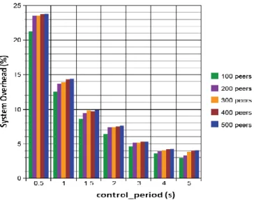
System overhead rate (%): This is the percentage of
bytes of the control messages (see section III.A.1) in relation to the total number of data bytes sent by the all system peers (chunks + control messages). Figure 5 shows the system overhead as function of the control_period, i.e. the period of exchange of the control messages. Results are presented for different network size (from 100 to 500 peers in the network). We noted that the system overhead decreases when
control_period increases, since the control traffic quantity sent
by the system peers during the simulation is decreasing. Moreover, this figure shows that the system overhead is almost independent of the network size. This is because the control messages are only exchanged between the peers and their neighbors. Based on these results we can assume that for a large network size our mechanism overhead remains low.
Missing chunk rate (%): As written in Section III.A, a
peer P considers a chunk Ck as missing if it does not receive all its packets before than TVtP becomes equal to k. To
Video rate 300 Kbps [13]
L_max 15 peers [13]
Video Source Bandwidth 2Mbps
Peer Upload Bandwidth 300 Kbps 4500 Kbps 600 Kbps
Peer Download Bandwidth 1 Mbps 1.5 Mbps 2 Mbps
Figure 5. System overhead as function of control_period Figure 6. Chunk missing rate as function of control_period
Figure 7. Comparison between the estimated control_rate and the real one
measure this metric, during the simulation, each peer computes the number of the required chunks and the number of chunks considered as missing. At the end of the simulation, we compute the percentage of missing chunks for all video chunks during the simulation. If it is at 0%, it means that all peers have received a perfect video.
Figure 6 depicts the missing chunk rate as function of
control_period. When the control_period is smaller than 1.5 s,
we note that the missing chunk rate is larger than zero and decreases with the increasing of control_period. In this case, as shown Figure 5, the peers exchange between themselves a large quantity of control messages. The absence of chunks is mainly due to the parameter control_rate. Indeed, as written in Section III.B, the estimated chunk transmission capacity of a peer P may be larger than the real one when P exchanges the control messages with a rate larger than control_rate. In this case, P may be considered as a sender for different receivers and may receive a number of chunk requests that are larger than its available transmission capacity. The transmitted chunks can be delayed or lost, which increases the probability of missing chunks in the system. In our simulations, some peers have suffered from this problem when the
control_period was smaller than 1.5s. Figure 7 give us
verification when control_period is equal to 0.5 s. The presented measure is carried on the peers that belong to the group G1 whose the number is equal to 6. These peers send chunks and control messages to the G2 group members, and only control messages to the video source (the group G0). The blue curve represents the control_rate value used to estimate the transmission capacities of these peers. It is constant and equal to 6×control_rate=78000 bps. The red line represents the sum of the real upload rate used by these peers to exchange the control messages. Figure 7 shows that with
control_period equal to 0.5, the control_rate used to estimate
the capacities of the G1 group members was smaller than the
real rate used by these peers to exchange the control messages. This explains the missing chunks in Figure 6 when the exchange period is smaller than 1.5s.
Moreover, Figure 6 shows that the chunk missing rate increases according to the increase of control_period when this period is larger than 3 s. The reason is that for a long
control_period, receiver must wait some time before locating
the new chunks within its neighbors. This can delay the chunk requests and reduces thus the chunk_reception_time, i.e. the time lag between the chunk requesting moment and its displaying deadline. The probability of receiving chunks with a delay will be high. This explains the existence of missing chunks with a large control_period. Additionally, Figure 6 shows when the control_period is smaller than 3 s, the missing chunk rate is independent from the network size. It is always equal to zero. This is due to our algorithms that ensure the availability of the neighbors whatever the network size is.
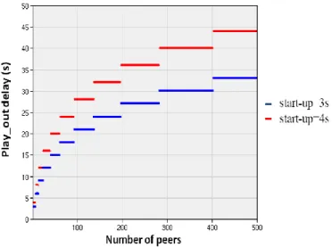
Figure 8. Peer‟s play-out delay
Play-out delay (s): This metric is local and different for
each peer. As we explained previously (see Section III.A), the peer play-out delay is equal to the play-out delay of its neighbors plus start-up delay. Figure 8 depicts the play-out delay as function of different start-up values and the number of peers. We used the same parameters presented previously with control_period equal to 3s. Note that the play-out delay of a peer P is independent from the control_period since P computes it initially and keeps it constant during the video session (see Section III.A). We remark that the play-out delay increases with the increasing of start-up since the peer undergoes an additional play-out delay relative to its neighbors. The first peers have a very low play-out delay since they belong to the first groups which are close to the source. Note that the maximum play-out delay observed with start-up equal to 3 s is 55 s for 500 peers which matches to the mean value observed in a real measurement of the current P2P systems [17]. However, as compared to these systems, our overlay construction mechanism ensures a chunk missing rate equal to 0. Furthermore, we used start-up equal to 3s. It is smaller than 5s which is the start-up made one by the P2P clients requesting the most popular channels, as observed in a real study [6].
V. CONCLUSION
In this paper, we have presented and evaluated a new mesh-based overlay construction mechanism for a pull-based P2P live streaming system. It consists of providing an overlay for each new peer, in which members are selected according to both their available transmission capacities and their play-out delay. We showed through simulations that our mechanism allows all the system peers to ensure a good video quality with a small play-out delay. The missing chunk rate and the system overhead remain almost constant in different network sizes. This explains the ability of our mechanism to provide good video quality for a large population. We currently perform extensive simulations to show the efficiency in high dynamic scenarios. In future work, we will implement a prototype of
our mechanism in a real network, and compare it with the existing pull-based systems.
REFERENCES [1] Sopcast, http://www.sopcast.com/.
[2] X. Hei, C. Liang, J. Liang, Y. Liu, and K. W. Ross. Insights into PPLive, “A measurement study of a large-scale P2P IPTV system,” In Proc. of IPTV Workshop, 2006.
[3] X. Zhang, J. Liu, B. Li, and T.-S. P. Yum, “Coolstreaming/donet: A data-driven overlay network for efficent media streaming,” In Proc. of IEEE INFOCOM, USA, 2005.
[4] T. Bonald, L. Massoulie, F. Mathieu, D. Perino, A. Twigg, “Epidemic live streaming: optimal performance trade-offs,” In Proc. of ACM SIGMETRICS international conference on Measurement and modeling of computer systems, USA, 2008.
[5] N. Magharei and R. Rejaie, “Prime: Peer-to-peer receiver-driven mesh-based streaming,” In Proc. of IEEE INFOCOM, USA, 2007.
[6] L. Vu, I. Gupta, J. Liang and K. Nahrstedt, “Measurement and modeling of a large-scale overlay for multimedia streaming,” In Proc. of the Fourth international Conference on Heterogeneous Networking For Quality, Reliability, Security and Robustness & Workshops, Vancouver, Canada, 2007.
[7] S.Banerjee, B. Bhattacharjee, C. Kommareddy, “Scalable Application Layer Multicast,” Technical report, UMIACS TR-2002.
[8] D. Tran, K. Hua, T. Do, “ZIGZAG: An Efficient Peer-to-Peer Scheme for Media Streaming,” In Proc. of IEEE INFOCOM, USA, 2003. [9] H. Magharei, R. Rejaie, and Y. Guo, “Mesh or multiple-tree: A
comparative study of live p2p streaming approaches,” In Proc. of IEEE INFOCOM, USA, 2007.
[10] M. Castro, P. Druschel, A. Kermarrec, A. Nandi, A. Rowstron and A. Singh, “SplitStream: High-Bandwidth Multicast in Cooperative Environments,” In 19th ACM Symposium on Operating Systems Principles, 2003.
[11] A. R. Bharambe, S. G. Rao, V. N. Padmanabhan, S. Seshan, and H. Zhang, “The Impact of Heterogeneous Bandwidth Constraints on DHT-Based Multicast Protocols,” In Proc. of the 4th International Workshop on Peer-to-Peer Systems, 2005.
[12] R. Dongni, Y. Hillman Li, S. Gary Chan, “On Reducing Mesh Delay for Peer-to-Peer Live Streaming,” In Proc. of IEEE INFOCOM, AZ, 2008. [13] M. Zhang, Q. Zhang, L. Sun, S. Yang, “Understanding the Power of
Pull-Based Streaming Protocol: Can We Do Better?,” In IEEE Journal on Selected Areas in Communications 25, 1678-1694, 2007.
[14] R. Kumar, Y. Liu, and K. Ross, “Stochastic fluid theory for p2p streaming systems,” In Proc. of IEEE INFOCOM, USA, 2007. [15] M. Zhang, Y. Xiong, Q. Zhang, L. Sun, S. Yang, “Optimizing the
Throughput of Data-Driven Peer-to-Peer Streaming,” IEEE Transactions on Parallel and Distributed Systems, vol 20 pp 97-110, 2009.
[16] “Meridian node to node latency matrix (2500×2500),” 2005, meridian project.:http://www.cs.cornell.edu/People/egs/meridian/data.
[17] X. Hei, C. Liang, J. Liang, Y. Liu, and K. W. Ross, “A measurement study of a large-scale P2P IPTV system,” IEEE Transactions on Multimedia, 2007.
[18] R. Lobb, A. Couto da Silva, E. Leonardi, M. Mellia, and M. Meo, “Adaptive overlay topology for mesh-based P2P-TV systems,” In Proc. of NOSSDAV '09. ACM, New York, 2009.
[19] J. Chakareski and P. Frossard, “Delay-based overlay construction in P2P video broadcast,” in Proc. of IEEE International Conference on Acoustics, Speech and Signal Processing, USA, 2009.
[20] Y. Liu, “On the minimum delay peer-to-peer video streaming: how realtime can it be?,” ACM Multimedia, Augsburn, DE, Septembre 2008. [21] L. Massoulie, A. Twigg, C. Gkantsidis, and P. Rodriguez, “Randomized
decentralized broadcasting algorithms,” In Proc. of IEEE INFOCOM, USA, 2007.