APPLICATION OF AN ADVANCED TRANSIENT STABILITY
ASSESSMENT AND CONTROL METHOD TO
A REALISTIC POWER SYSTEM
D. Cirio, D. Lucarella,G. Vimercati S. Massucco, A. Morini, F. Silvestro D. Ernst, M. Pavella, L. Wehenkel CESI S.p.A Milano, Italy vimercati@cesi.it University of Genova Genova, Italy massucco@epsl.die.unige.it University of Liège Liège, Belgium L.Wehenkel@ulg.ac.be Abstract – The paper presents a technical overview of a
large research project on Dynamic Security Assessment (DSA) supported by EU. Transient Stability Assessment and Control, which was one of the main goals of the project, is taken into consideration by presenting the fundamental theoretical methodology and possible applications. A specific prototype installation for a realistic power system is then reported by presenting and commenting some of the obtained results.
Keywords: Dynamic Security Assessment, Transient Stability, Preventive Control, Generation Rescheduling.
1 INTRODUCTION
Power systems have traditionally been operated based on a background of previously performed studies and on the experience of dispatcher operators. Such practice usually leads to conservative limits and often cannot comply with market requirements to fully exploit power system equipment, plants and facilities and with transparency criteria in case of conflictual decisions imposed by regulating bodies. On the other hand, the operator may have to face new operating conditions brought about by the restructured power market and may lack adequate experience to operate the system, the current trend being to operate power systems closer and closer to their limits. This results in increased risks of instability, both of the transient and of the voltage type [1].
These considerations emphasise the need for accurate evaluation of security, performed on different phases of power system operation and in particular made available to the control room operator for on-line assessment. The accurate evaluation of security margins may result in more transactions accepted, thus improving competition without jeopardizing the overall integrity of the system and preventing the risk of severe outages and black-out. A better compromise between market and power system security requirements may then be achieved.
Although severe system outages are typically caused by several different concomitant conditions, recent and remote black-out histories testify that an effective and timely monitoring of the systems might have prevented
them from total collapse or, at least, might have significantly helped in reducing the dimension and duration of the outage both in the emergency conditions and in the restoration phase.
The tremendous advances in computer science and technologies have provided the technical support and environment for on-line applications of methodologies concerning DSA that have been developed in the last decades. General DSA requirements and some of these applications have been thoroughly reported in [2]. Other tentative applications are reported in [3], [4].
In the DSA context, a research project partially supported by the European Union within the aims of the Framework V- Energy scheme and named OMASES – Open Market Access and Security Assessment System [5] has produced interesting results.
OMASES developed an integrated DSA tool that attempts to cope with the above mentioned challenging requirements. A software platform composed of integrated tools is linked to existing Energy Management Systems (EMS) to get power system data on-line and to perform Dynamic Security Assessment (DSA) analyses within a time suitable for on-line operation and preventive action implementation.
The OMASES tool performs four main functions: Transient Stability Assessment (TSA), Voltage Stability Assessment, Training Simulator and Market Simulator. The experimentation phase consisted of applying and testing the tool on-line at two different sites, namely at HTSO (the Greek Transmission System Operator) [7] and at CESI [4] (a Research Centre that operated a remote connection to GRTN, the Italian TSO).
The next sections of the paper focus on Transient Stability Assessment and Control (TSA&C) activities performed on the Italian experimentation site.
2 OMASES: A SYNTHETIC PRESENTATION
2.1 Generalities
OMASES aim was to provide Energy Management System (EMS) operators with a DSA tool to be used on-line during the normal cycle of real-time operation, in operational planning and as a dispatcher training simulator including a simulation of the deregulated electric market environment. OMASES is realized
through various application functions: TSA – Transient Stability Assessment, VSA – Voltage Stability Assessment, TS – Training Simulator and MS – Market Simulator.
OMASES can be inserted in existing EMS or engineered into new EMS structure as it is essentially based on a LAN structure for inter-machine communications allowing easy hardware and software integration. The four OMASES Application Functions (TSA, VSA, MS, TS) run in a distributed environment, with a link to the host EMS over which a real-time picture of the power network is obtained. The overall architecture, shown in Figure 1, includes: a data server which hosts any shared information, database systems, message systems, etc.; an appropriate server (even in parallel computing configuration) for each Application Function; computer systems to be used by operation personnel for user interface processes.
EMS
Figure 1: OMASES architecture and Application Functions Three different operating modes are made available to system operators: (1) Engineering mode, (2) Real-time mode, (3) Training mode.
(1) Engineering mode: off-line application of TSA and VSA studies involving or not the market environment and performed mainly for planning purposes
(2) Real-time mode: the EMS feeds OMASES with network data and solutions. DSA is synchronized with data transfer and cyclically runs with an overall execution time within 15 minutes
(3) Training mode: the operator gets used with the DSA tools and power system dynamics, performs analysis (future scenarios, post-event analysis, etc.) of the existing electrical system and/or experiments. Market rules can be used to provide realistic scenarios.
2.2 DSA Application Functions
DSA tools for the Engineering mode are relatively widely available at least for TSA and VSA. These are in fact quite mature methodologies and techniques. Effective Real-time mode and realistic Training mode applications have been developed and are still under test [2], [3], [4]. It is instead evident that both TS and MS are much more related to specific requirements posed by existing simulation tools adopted by each TSO and by specific market structure. Therefore, within OMASES, MS is intended to provide credible scenarios
for subsequent TS and DSA activities and TS is strictly related to one specific simulator.
The TSA and VSA Application Functions operate in a similar way by investigating a large number of contingencies (that may amount to almost one thousand for large power systems), by filtering them and ranking in accordance to their severity. Advanced tools also provide possible remedial actions for those contingencies that may affect system security. Each of the TSA and VSA functions calculates system security indices and margins for a set of contingencies applied on a real time scenario directly taken from the EMS (Real-time mode) or a simulated one generated by the TS (Training mode).
The VSA Application Function [6] integrates software tools for the assessment of Voltage Security into the DSA package of the OMASES platform. This includes, among others, the analysis of the impact of significant contingencies and the determination of secure operation limits in terms of power transfers in critical corridors or power consumption in load areas. For a given direction of stress and a given contingency, the Secure Operation Limit (SOL) of the system corresponds to the most stressed pre-contingency operating point such that the system responds to the contingency in an acceptable way [7].
Within OMASES the TS is expected to run on-line or in the Training mode. In the former case it has to play interactively any scenario starting from an actual operating point extracted from the EMS and taking into account any kind of disturbances or operator actions. In the latter case, the simulator must reproduce the real time, that is to say that an accurate simulated state of the system must be displayed at the operator station according to the refreshment time of the EMS (about 2 to 10 s). To reach this twofold target, OMASES bases its developments on two different codes proprietary of Tractebel: EUROSTAG and FAST [8].
Transient Stability Assessment and Control (TSA&C) being the core of the presented application, the next section is dedicated to SIME [9] that is the specific method adopted in OMASES.
2.3 TSA&C: Transient Stability Assessment & Control
The SIME (for SIngle Machine Infinite Bus Equivalent) method has been developed at the University of Liege [10]. The SIME method is a hybrid method based on a generalized One-Machine Infinite Bus (OMIB) method. More precisely, it is a hybrid, temporal-direct method: temporal, since it relies on the multi-machine system evolution with time; direct, like the EEAC (for Extended Equal-Area Criterion) [11], from which it originates.
SIME transforms the trajectories of a multi-machine power system provided by a time-domain program into the trajectory of a OMIB equivalent. SIME drives a time-domain (T-D) transient stability program to extract, step-by-step, the multi-machine system parameters and transform them into the OMIB ones.
The fundamental difference between the original version of EEAC and SIME is that EEAC relies on a
time-invariant OMIB that it constructs by assuming the classical simplified machine and network modelling and by ``freezing'' once and for all the machine rotor angles at the time of the disturbance inception. As a consequence, EEAC is a pure direct method, free from any transient stability program; it thus yields analytical expressions that are extraordinarily fast to compute, but introduces approximations about the machines coherency and their (over)simplified modelling.
The SIME method instead refreshes the OMIB parameters at each time step of the time-domain program. It calls upon the Equal-Area Criterion (EAC), in order to identify the critical machines (CMs) and to compute stability margins. By doing so, SIME achieves:
• fast stability analysis, in terms of stability limits
relative to a contingency scenario
• ultra fast contingency screening • sensitivity analysis
• control, i. e., design of countermeasures able to
stabilize an unstable scenario
• physical insight and interpretations via EAC.
SIME may be used in: expansion planning, for screening contingencies and for sensitivity analysis; operation planning, for congestion management problems and for ATC (Available Transmission Capacity) calculations; real-time operation, in a preventive mode, for scanning a set of plausible contingencies, identifying the harmful ones, assessing their severity and proposing to the operator remedial actions able to make the system withstand such contingencies. A further implementation can use real-time measurements in order to identify the actual occurrence of a contingency, its degree of severity, and, whenever this contingency is found to be harmful, to design and trigger appropriate remedial actions, in real time [10].
In the following, a short description of various operations by SIME is provided.
Computation of stability limits. The search of stability limits (critical clearing times – CCT, or power limits) generally relies on the computation of margins and their pair-wise extrapolation. The search is iterative and proceeds by simulating successive unstable cases of decreasing severity, assessed by their negative margin. The simulations stop as soon as a stable case is met. Contingency filtering. The approximate search of a first-swing stability limit generally requires only two unstable simulations. Thus, given a clearing time, the contingency will be: either first swing stable; or first swing unstable (i.e. margin η < 0).
In the latter case, a more refined classification into multi-swing harmless, potentially harmful or harmful contingency may be obtained, using a second simulation with a smaller clearing time.
Transient stability control. Stabilizing an unstable contingency (i.e. a contingency with a negative margin) is equivalent to canceling out its margin. Increasing the margin to zero and up, may be obtained by acting on the
OMIB mechanical power. By using the equal-area criterion (EAC), a first guess of the total generation power to be shifted from critical machines (CMs) to non-critical machines (NMs) can be provided.
As NMs are generally many more than CMs, the corresponding rescheduling of NMs may be conducted so as to comply with additional (e.g. economic) objectives.
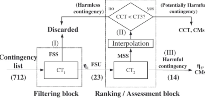
Contingency FILtering, Ranking & Assessment (FILTRA). Contingency filtering ranking and assessment is schematically represented in Figure 2 that consists of two blocks.
1st Block: For a given clearing time CT1, the contingencies are classified
• either as First Swing Stable (FSS) and are
discarded
• or as First Swing Unstable (FSU) and are sent to
the second block, along with the corresponding negative margin, η1.
2nd Block: each FSU contingency is reconsidered, using a CT2 < CT1 and
• if η2 < 0, the contingency is declared to be harmful
• otherwise, i.e., if η2 > 0, the contingency is declared
to be Multi Swing Stable (MSS). Its critical clearing time (CCT) is computed by interpolation and compared to a third CT3, and if:
- CCT > CT3, the contingency is declared to be
harmless and is discarded.
- CCT< CT3 the contingency is declared to be
potentially harmful and stored for possible
reconsideration after stabilization of the harmful contingencies.
Figure 2: FILtering Ranking and Assessment (FILTRA).
Numbers in brackets correspond to a stability exploration of the Brazilian system [10]
Integrated transient stability assessment and control. Within the OMASES project, the various tasks to be performed by the integrated Transient Stability Assessment and Control (TSA&C) scheme for stabilizing on-line possible transient instabilities in the preventive mode are described in Figure 3 for a single-processor solution.
Application of parallel processing is possible with no particular complication of the overall framework and may provide significant increment in computational speed. CT1 FSS CT2 MSS Interpolation Discarded (Harmless contingency) Harmful contingency yes no CCT < CT3?
Filtering block Ranking / Assessment block Contingency list (Potentially Harmful contingency) (I) (III) (II) FSU ηηηη1 ηηηη2, CMs CCT, CMs (712) (23) (14)
The TSA&C scheme works in the following way. The output of the Energy Management System (EMS) state estimator provides the data for obtaining the Operating State (OS) of the system. The OS can be obtained by running: (a) either a power flow program or (b) an Optimal Power Flow (OPF) program for computing an operating condition which meets a predefined objective function (e.g., maximum power transfer on predetermined tie-lines; minimum generation cost; etc), while respecting the static constraints of the transmission network elements (bus voltage and power line limits). The operating state and a list of possible contingencies selected by the operator are sent to the FILTRA block.
The FILTRA package (block (1) in Figure 3) identifies the set of unstable (harmful) contingencies from a very large initial set of probable contingencies. At the same time, it also computes stability margins and finds the set of critical machines corresponding to each one of the unstable contingencies.
Figure 3: Transient Stability Assessment & Control After receiving the information about critical machines and margins, the Transient Stability Control Block (block (2) in Figure 3) performs the stabilization of the harmful contingencies. This procedure can be
done for stabilizing a single contingency (the most critical one) or a selected set of harmful or even the whole set of harmful contingencies. This is a choice the operator must make depending on the current operating policy. As an example, for stabilizing the whole set of harmful contingencies, the integrated TSA&C scheme performs the following functions:
- determine the corresponding control actions (the
total active generation shift from Critical Machines to Non-Critical machines) for each one of the unstable (harmful) contingencies;
- determine the generation shift on each critical
machine, from the total generation shift, for each one of the unstable (harmful) contingencies;
- combining the resulting control actions, compute
the amount of active power change on each critical machine, necessary to stabilize all harmful contingencies simultaneously.
The reschedule of system machines is then performed using a conventional power flow program. Generation shifting is directly applied on critical machines and the corresponding amount of active power reallocation on non-critical machines is performed considering several criteria. As an example, the power on non-critical machines can be assigned in proportion to their inertia coefficient.
The improved operating state and the list of harmful contingencies are sent to the Transient Stability Assessment Block (block (3) in Figure 3) that assesses again the transient stability of the power system with respect to the set of harmful contingencies. If the assessment block finds that the system is still unstable under some contingencies, it computes the corresponding margins, identifies the critical machines and sends this information back to the Transient Stability Control block (2). If the power system is stable for all contingencies, the new operating state is declared to be secure and the process stops.
The cycle is repeated until stabilizing all unstable contingencies. It is found that, generally, the process converges to the solution after two to three iterations. A final check is then performed to verify that the procedure has not destabilized any of the previously potentially harmful contingencies (mandatory) and harmless contingencies (optional).
3 APPLICATION TO A REALISTIC SYSTEM
3.1 Set-up of the Experimentation Site
The Italian test site was installed in December 2002. The experimentation concerned portability issues, in particular the operation of the data transfer module between Italian EMS and OMASES platform: both the automatic file creation and transfer in real time mode, and the system model conversion in the OMASES format were thus checked. The experimentation also regarded the correct operation of the platform from a software standpoint, and the output consistency of the DSA functions.
Contingency Filtering, Ranking and Assessment (FILTRA)
State Estimator (EMS) Contingency List Stable Operating State Proposed (New) Stable Operating State System
Operating State (e.g., 1000)
Unstable Contingencies (margin < 0) ? Yes No (1) Transient Stability Assessment & Control
No Improved Operating State after applying the Preventive Control
Actions
StabilityMargins , Critical Machines Yes
Transient Stability Control
Finding preventive control actions to stabilize the system operating state
Transient Stability Assessment
Unstable Contingencies (margin < 0) ? (2) (3) Stop
Within the Italian experimentation site, OMASES TSA and VSA functions have been tested both in the Real-time mode (on-line) and in the Engineering mode (off-line) [4], [6]. The experimentation of TS and MS were out of scope of this Experimentation Site.
The Real-time mode is mainly concerned with the overall platform testing, and with the filtering/ranking capabilities, as it is rare that truly jeopardised situations occur: in fact the Italian power system is usually operated in a conservative manner, with N-1 (and sometimes even N-2) criterion being satisfied.
The Engineering mode is more suitable for a systematic validation of the tool capabilities and its tuning. In particular, it makes it possible to check the output of the tool when heavily stressed scenarios are concerned. In the Engineering mode, if the initial conditions are “excessively” secure, the power system may be stressed in a variety of ways: for instance: by increasing the load or the power transfer between areas, by weakening the topology and/or the generation capacity, by creating low voltage conditions. The aim is to find the system limits and to compare suggested preventive actions with those used in the past or suggested by operator’s experience.
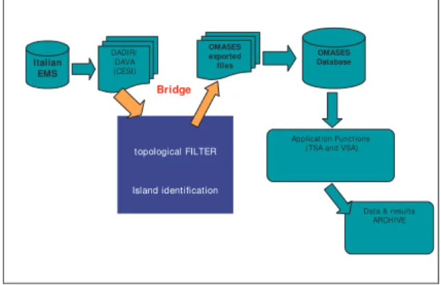
In order to fit the Italian EMS snapshots into the OMASES database, a bridge between the Italian EMS and OMASES was realized at the Italian site. The bridge performs data conversion to the OMASES format and can be used for on-line acquisition of the data which are then processed. The bridge from EMS data to OMASES data was developed by CESI.
Besides data format translation (sometimes including also model adaptations), an “island filter” was included to provide OMASES with a single electrical island data, as the presently developed platform is able to process only one connected network at a time. The overall importation scheme is reported in Figure 4. The import tool is not optimised, but it can fulfil the needs of the experimentation. In the Real Time mode the estimated snapshot of the network was loaded every 15 minutes.
The file transfer was performed on a Wide Area Network (WAN). The final installation within a TSO can be on a Local Area Network (LAN), faster than the former solution. DADIR/ DAVA (CESI) OMASES exported files OMASES Database Application Functions (TSA and VSA) Italian
EMS
Bridge
topological FILTER
Island identification
Data & results ARCHIVE
Figure 4: Data import from EMS
This import tool demonstrates, as confirmed by the tests, that OMASES platform can be installed in
different EMS systems. The platform can in fact be “plugged” into existing EMS databases, by building an appropriate “bridge”.
3.2 The Italian Power System
The network under analysis was the complete Italian power system as in 2003, provided by the National TSO. It consists of the 400 kV and 220 kV and the main 150 kV lines and stations, along with generators and equivalent loads. It is stored in the OMASES database used in the Real-Time mode.
The Italian power system is characterised by a significantly longitudinal structure, which leads to the definition of critical interfaces (also called critical sections). An instance of critical interface is the interconnection with Central Europe, constituted by 15 tie-lines of which 6 are 400 kV lines and 9 are 220 kV lines.
Electrical energy import is very important for Italy, and the interconnection is highly stressed. Moreover, also the internal North-to-South connections exhibit similar characteristics. The loss of a line on a critical interface may cause overloads on the remaining lines or dynamic problems. Hence, the corresponding scenarios need to be properly evaluated in terms of dynamic evolution, by performing contingency filtering and ranking.
The examined Italian network consisted of:
Grid: 1118 Lines; 7234 Nodes – about 1500 Buses
The number of buses depends on the actual state of the network whereas the number of nodes is a network characteristic. The bus number is related to the actually energised nodes; 5778 Switches (1018 Bus bar couplers);
Machines: 467 Synchronous generators, AVRs,
system excitation limits; Hydraulic, Thermal (steam and gas) Governors and turbines;
Transformers: 1082 two/three windings, 363 ULTC Loads: 1046 Static and dynamic loads.
The grid description – in terms of network description and operating condition – was imported automatically from existent network database whereas the dynamic description, both for long term dynamics and short term dynamics, was provided either by hand or partially automatically downloaded by database, and makes use of different models for TSA and VSA.
TSA systematically performs the following tasks: (a) investigate large numbers (hundreds) of (credible) contingencies; (b) extract a subset of those that may threaten system security (contingency filtering and ranking); (c) provide possible preventive remedial actions.
The most important aspect of the TSA validation phase at CESI site concerned its functionality, particularly for the FILTRA function that allows selecting potentially harmful contingencies. This has been tested and the present section reports on relevant results. A significant aspect of the testing consisted of comparing the simulation outputs of the TSA functions with a reference that represents the “real” system
behaviour. For the Italian system this reference has been the electromechanical and long-term simulator SICRE [12], developed by CESI. As the OMASES Application Function TSA used the Eurostag package [9], it was important for the models adopted in the OMASES TSA Application Function to be comparable to those implemented in SICRE. Proper adaptations to reproduce the models originally used in the Italian simulator were required.
The OMASES simulator Eurostag is a powerful simulator, which allows the user to build his own dynamic models. A preliminary consideration concerns the time span that is going to be simulated: in the case of TSA, a few seconds are sufficient, since experience suggests that multi-swing transient instability phenomena are not likely to occur in the Italian system. This allowed neglecting the slow dynamics that a simulator takes into account. Under such assumptions, for example, the boiler representation (steam plants) can be highly simplified, and LTCs can be assumed fixed. The most important models related to TSA concern, in fact, the representation of synchronous machine, AVR, PSS, and turbine governor. Apart from the synchronous machine, the other models were built by means of Eurostag macro-blocks reproducing the standard Italian AVR and PSS models. Proper adaptations were made to implement turbine governors.
3.3 Results from TSA testing
The functionality of TSA has been tested as described in the following. A snapshot of the EMS output is correctly transferred to the OMASES database. In the Real-Time mode the following operations are automatically performed:
(1) Dynamic data preparation (TSA folder and
configuration file creation)
(2) Retrieving of contingency and other TSA
parameters from the database
(3) Loading of static system data and execution of
load flow
(4) Execution of FILTRA and CONTROL modules,
including the necessary dynamic simulations. The settings related to TSA FILTRA operation are stored in the TSA database as well as the data for dynamic simulation. Different sets of contingencies have been used to verify the TSA function.
A complete set of three-phase short circuit contingencies followed by line tripping for (N-1) criterion analysis in the entire network was initially tested. Critical lines have been identified and mainly corresponded to lines connecting, or close to, power plants and specifically for those plants weakly connected to the HV grid. Table I reports a list of contingencies selected for analysis. Further, some interconnection lines located in the production areas in the South of Italy have been tested.
During real-time experimentation, the Italian network did not experience any particular transient stability problem.
Line ID Description (faulted line)
Cont_220 kV_line _16 BIELLA EST-->TURBIGO ST Cont_220 kV_line _17 SPEZIA STA-->AVENZA Cont_220 kV_line _18 SPEZIA STA-->COLORNO Cont_220 kV_line _19 MESE-->GORDUNO Cont_220 kV_line _20 SONDRIO-->ROBBIA Cont_220 kV_line _28 OSTIGLIA-->BUSS. S.S. Cont_400 kV_line _14 TURBIGO ST-->RONDISSONE Cont_400 kV_line _16 OSTIGLIA-->DUGALE Cont_400 kV_line _17 OSTIGLIA-->FERRARA F. Cont_400 kV_line _22 PORTOTOLLE-->FORLI' Cont_400 kV_line _29 RAVENNA C.-->PORTOTOLLE Cont_400 kV_line _34 MONTALTO-->SUVERETO Cont_400 kV_line _42 PRESENZANO-->VALMONTONE Cont_400 kV_line _9 SPEZIA STA-->MARGINONE
Table I: Partial list of the most representative contingencies for TSA
Figure 5 reports some results referring to a real case analysed during the testing phase. With reference to Figure 2 in section 2.3, the FILTRA parameters were selected as: CT1 = 300 ms, CT2 = 250 ms, CT3 = 200 ms, that represent the thresholds for considering a three-phase short circuit contingency respectively “FSU”, “harmful” and “potentially harmful”.
It can be noted that the list of dangerous contingencies is really small compared to the full list of contingencies filtered, as nearly all of the analysed cases were found first-swing stable (FSS in Figure 5).
Output of FILTRA module
Figure 5: Output of FILTRA module: TSA parameters and
list of contingencies ranked in a severity order
One major aspect of FILTRA is the capacity to assess the dangerous contingency faster than the CCT calculation, even if the calculus of the CCT is not exact. In fact, for example, the contingency MM1317 is declared unstable (HS in Figure 5) with a CCT larger than 290 ms, while the exact value calculated is 296 ms. On the other hand the identification of this contingency as a dangerous one is correct. In any case, by a particular functionality of the FILTRA module, it is possible to assess very precisely the CCT of each
contingency. This powerful facility is more dedicated to the engineering mode of the OMASES platform.
One major value of the TSA function is to provide the operator with a list of possible actions to stabilise the system against a set of contingencies. The control function suggests how to stabilize the contingencies declared harmful by FILTRA and evaluates the power that should be re-scheduled from the critical to the non-critical machines. An example of the results of this action related to one harmful case is reported in Table II.
Figure 6 reports the details concerning the most severe identified harmful contingency for the examined case. It is taken from the OMASES User Interface for the Real Time mode. Several pieces of information are provided, among which the name of the contingency, the detail of each simulation (clearing time, margin, stability judgement, simulated time etc.), the computed CCT and the final rank.
Rescheduling of Critical Machine for one specific harmful contingency identified by FILTRA
Machine name Initial power in MW Final power in MW Difference in MW
ANPPG2 73.30 63.56 9.738 ANPPG3 78.20 68.46 9.738 BRNNG3 181.20 161.06 20.143 ROSNG1 296.70 274.85 21.849 ROSNG2 316.10 294.25 21.849 ROSNG3 320.00 298.15 21.849 ROSNG4 304.60 282.75 21.849 TIMPG4 280.70 258.85 21.849 TIMPG5 279.40 257.55 21.849 ISBAGA 159.50 139.25 20.249 ISBAGC 156.00 135.75 20.249 SFMPG3 160.00 148.79 11.215 ROSNGA 88.90 80.63 8.271 ROSNGC 98.50 90.23 8.271 ROSNGE 102.00 93.73 8.271 TIMPGA 110.60 102.33 8.271 TIMPGC 112.50 104.23 8.271 BSCNG1 637.00 448.94 188.060 BSCNG2 652.80 464.74 188.060 BSCNG3 617.20 429.14 188.060 BSCNG4 622.40 434.34 188.060 SFMPG6 244.40 222.55 21.849 ISBAG1 108.50 91.77 16.731 ISBAG2 107.30 90.57 16.731
Table II: Rescheduling of Critical Machines for a harmful contingency
The OMASES TSA function was also tested for heavily stressed system conditions, generated on purpose. In this case, the starting point consisted of a real time snapshot, and the stress was implemented by a topology change. The considered situation was that of 12/6/2003 at 11:30, characterised by a very high demand due to temperature rather higher than usual. A weakening of the system was then obtained by opening a line near Brindisi power station (South of Italy).
For this stressed case, the validation phase included comparison of the simulation outputs of the TSA function with the electromechanical and long-term simulator SICRE, developed by CESI, taken as the reference. A complete comparative analysis is here
reported for contingency affecting line NN1322. When performing a full simulation with SICRE a dichotomy process was used to assess the CCT related to the outage of this line. The approximate value of the CCT computed with SICRE is about 135-140 ms, against the value calculated by FILTRA, i.e. 142 ms.
Figure 6: FILTRA output for the modified case The artificially stressed operating point mentioned above, caused a low critical clearing time (CCT = 117 ms) for a three-phase short-circuit fault on the Brindisi– Taranto line (NN1320) close to Brindisi power station. Figure 7 shows the identified critical machines of Brindisi power plant. These machines matches with the analysis performed SICRE. The OMASES Control function determined the margin and the amount of power to be re-scheduled among the non-critical machines in order to make the system able to withstand this contingency (NN1320) with an imposed new clearing time of 180 ms, quite larger than the previously computed CCT of 117 ms.
Figure 7: FILTRA results and critical machines of Brindisi
power station
Table III presents the final output of the OMASES Control function: it helps the operator to re-schedule properly the power of the critical machines to non critical machines for a total amount of about 468 MW.
The amount of power to be re-scheduled is significantly large. Therefore to reduce it, the control function was run again with a less demanding requirement: the desired clearing time of the system was
set at the value of 150 ms. Table IV shows that the amount of power to be re-scheduled is drastically decreased (257 MW) but, as it is clearly shown, the Critical machines are many more.
Rescheduling of Critical Machine Machine
name Initial power in MW Final power in MW Difference in MW
BRNNG3 181.20 160.94 20.265
BSCNG1 637.00 525.09 111.909
BSCNG2 652.80 540.89 111.909
BSCNG3 617.20 505.30 111.899
BSCNG4 622.40 510.50 111.899
Table III: Output of the Control function for the stressed case, contingency NN1320
Rescheduling of Critical Machine Machine
name Initial power in MW Final power in MW Difference in MW
BRNNG3 181.20 175.16 6.043 TIMPG4 280.70 274.66 6.043 TIMPG5 279.40 273.36 6.043 ISBAGA 159.50 153.91 5.594 ISBAGC 156.00 150.41 5.594 SFMPG3 160.00 156.90 3.103 TIMPGA 110.60 108.31 2.289 TIMPGC 112.50 110.21 2.289 BSCNG1 637.00 585.88 51.117 BSCNG2 652.80 601.68 51.117 BSCNG3 617.20 566.08 51.117 BSCNG4 622.40 571.28 51.117 SFMPG6 244.40 238.36 6.043 ISBAG1 108.50 103.87 4.625 ISBAG2 107.30 102.67 4.625
Table IV: Output of the Control function for the stressed case, contingency NN1320: alternative solution.
4 CONCLUSION
The paper has presented a technical overview of a significant European Research Project on Dynamic Security Assessment. The presentation specifically focused on the Transient Security Assessment function for identifying harmful and potentially harmful contingencies in power system operation. The function is also able to suggest preventive countermeasures so as to bring power system operating point back from alert to normal condition.
The experimentation phase proved that OMASES can effectively be linked to an existing Energy Management System, e.g. a proprietary system with its own system model and data format, such as the Italian one. The only requirement consists of developing an appropriate bridge for on-line data acquisition and conversion into OMASES format.
The real time tests showed the functionality of the on-line platform and, in particular, the filtering/ranking capabilities of the tool. Some off-line studies performed on artificially stressed scenarios allowed to confirm the ability of the package to correctly identify critical situations and provide preventive control countermeasures, such as generation re-scheduling.
Results of the experimental process permitted the tuning and validation of the DSA platform in terms of
experience and feed-backs for what concerns the effective possibilities of filtering, screening and stabilizing contingencies in large electrical power systems.
ACKNOWLEDGMENTS
The OMASES research was carried out within the EU project OMASES - Open Market Access and Security Assessment System, EU Contract N. ENK6-CT2000-00064, December 2000.
Damien Ernst is a Post-doctoral researcher of the Belgian FNRS.
REFERENCES
[1] Proceedings of the IEEE, Special Issue on the Technology
of Power System Competition, Vol. 88, No. 2, February 2000
[2] P. Kundur, K. Morrison, L. Wang, “Power System
Security Assessment”, IEEE Power & Energy Magazine, Vol. 2, N. 5, September/October 2004, pp. 30-39.
[3] K. Demaree, T. Athay, K. W. Cheung , Y. Mansour, E.
Vaahedi, A.Y. Chang, B.R. Corns, B.W. Garrett, “An On-line Dynamic Security Analysis System Implementation”, IEEE Transactions on Power Systems, Vol. 9, No. 4, November 1994, pp. 1716-1722
[4] A. Bihain, D. Cirio, M. Fiorina, R. Lopez, D. Lucarella, S.
Massucco, D. Ruiz Vega, C. Vournas, T. Van Cutsem, L. Wehenkel, “OMASES: A Dynamic Security Assessment Tool for the New Market Environment”, IEEE BPT Powertech, Bologna, June 23-26, 2003
[5] OMASES - Open Market Access and Security Assessment
System, EU Contract N. ENK6-CT2000-00064, December 2000
[6] C. D. Vournas, G. A. Manos, J. Kabouris, G.
Christoforidis, G. Hasse, T. Van Cutsem, “On-Line Voltage Security Assessment of the Hellenic Interconnected System”, IEEE Bologna Powertech 2003 Conference, Bologna (Italy), June 23-26, 2003
[7] T. Van Cutsem, C. Vournas, “Voltage Stability of Electric
Power Systems”, Kluwer Academic Publishers (Power Electronics and Power Systems Series), Boston, 1998 [8] S. Gissinger, P. Chaumes, J.-P. Antoine, A. Bihain,
M.Stubbe: “Advanced Dispatcher Training Simulator”, IEEE Computer Applications in Power, Vol. 13, No. 2, 2000, pp. 25-30
[9] M. Pavella, L. Wehenkel, Y. Zhang, “SIME: A hybrid
approach to fast transient stability assessment and contingency selection”, Electric Power & Energy Systems, Vol. 19, No. 3, 1997, pp. 195-208
[10]M. Pavella, D. Ernst, D. Ruiz-Vega, “Transient Stability of Power Systems - A unified approach to assessment and control”, Kluwer’s Power Electronics and Power Systems Series, October 2000
[11]Y. Xue, Th. Van Cutsem, M. Ribbens-Pavella. "A simple direct method for fast transient stability assessment of large power systems". IEEE Trans. on PWRS-3:400-412, 1988
[12]P. Baratella, P. Scarpellini, R. Marconato, B. Cova, E. Gaglioti, R. Zacheo, “A Power System Simulator Covering Different Time Scale Phenomena: Models, Algorithms, MMI and Test Results”, Proc. IEEE Stockholm Power Tech, Stockholm, June 1995, pp. 376-381.