Departement de genie chimique et de genie biotechnologique
Synthese de poudres nanocomposites et depots de
cathodes pour les piles a combustible a temperature
moyenne
Nanocomposite Powder Synthesis and Cathode Coating
Deposition for Intermediate Temperature Solid Oxide
Fuel Cell
Memoire de maitrise Specialite: genie chimique
Yan SHEN
Jury: Fran5ois Gitzhofer, ing.PhD (directeur) Nicolas Abatzoglou, ing.PhD, professeur Nadi Braidy, ing.PhD professeur
Sherbrooke (Quebec) Canada February 2011
B#1
Published Heritage Branch 395 Wellington Street Ottawa ON K1A0N4 Canada Direction du Patrimoine de l'6dition 395, rue Wellington Ottawa ON K1A 0N4 CanadaYour file Votre rtf&rence ISBN: 978-0-494-83721-4 Our file Notre reference ISBN: 978-0-494-83721-4
NOTICE:
The author has granted a non
exclusive license allowing Library and Archives Canada to reproduce, publish, archive, preserve, conserve, communicate to the public by
telecommunication or on the Internet, loan, distrbute and sell theses
worldwide, for commercial or non commercial purposes, in microform, paper, electronic and/or any other formats.
AVIS:
L'auteur a accords une licence non exclusive permettant d la Biblioth6que et Archives Canada de reproduire, publier, archiver, sauvegarder, conserver, transmettre au public par telecommunication ou par Nnternet, prfiter, distribuer et vendre des th&ses partout dans le monde, d des fins commerciales ou autres, sur support microforme, papier, 6lectronique et/ou autres formats.
The author retains copyright ownership and moral rights in this thesis. Neither the thesis nor substantial extracts from it may be printed or otherwise reproduced without the author's permission.
L'auteur conserve la propri£t6 du droit d'auteur et des droits moraux qui protege cette thdse. Ni la thdse ni des extraits substantiels de celle-ci ne doivent §tre imprimis ou autrement
reproduits sans son autorisation.
In compliance with the Canadian Privacy Act some supporting forms may have been removed from this thesis.
While these forms may be included in the document page count, their removal does not represent any loss of content from the thesis.
Conform6ment £ la loi canadienne sur la protection de la vie priv6e, quelques formulaires secondares ont 6t6 enlev£s de cette th&se.
Bien que ces formulaires aient inclus dans la pagination, il n'y aura aucun contenu manquant.
Dans ce travail, des poudres nanocomposites contenant des phases melangees nano et micro-structurees de cathodes pour les piles h combustible k temperature moyenne (IT-SOFCs) ont
6t6 produits en utilisant un plasma thermique inductif. Deux techniques ont ete utilises, soit la
deposition en utilisant des suspensions (SPS) ou encore en utilisant des solutions (SolPS ou SPPS ). La cathode composite est un melange de conducteur electronique et de conducteur ionique (oxyde c6ramique) avec assez de porosite pour que l'oxygfcne passe et aussi pour assurer la compatibilite des coefficients d'expansion avec l'electrolyte. Afin de permettre la commercialisation des SOFCs, le d6veloppement des SOFCs s'oriente vers des piles fonctionnant & une temperature ambiante moyenne (600-8(X)oC). Ceci augmente le choix des
materiaux et des geometries de pile qui peuvent etre employes, reduisant les couts et, en principe, devrait aussi diminuer le taux de degradation des composants des piles et des syst&mes. Afin de reduire la resistance de polarisation de la cathode k cette gamme de temperature, on propose deux approches pour la fabrication de la cathode : a) en utilisant les materiaux avec des conductivity ioniques et eiectroniques eievees, qui peuvent etre obtenus en ajoutant une deuxfeme phase dans la cathode ; b) la synthese de cathodes avec des morphologies optimisees de nano/microstructure.
La methode SolPS a ete employee pour synthetiser des nanopoudres possedant une conductivite mixte. Le precurseur de la solution a ete prepare avec des nitrates, la glycine et l'eau distil lee stoechiometriques melanges en metal. La cristallinite et la morphologie des nanopoudres ont ete caracterisees par la diffraction de rayon X (DRX), la microscopie electronique & balayage (MEB), la microscopie electronique & transmission (MET) et la spectroscopic k dispersion d'energie (EDS). Des suspensions, faites avec de l'ethanol et les nanopoudres composites precedemment syntheses, ont ete employees pour deposer des revetements de cathode par le procede SPS. Les parametres des procedes SPS ont ete
optimises. Des cathodes nanostructurees produites par le procede SPS ont ete comparees a celles produites en utilisant le procede SolPS. Les revetements ont ete caracterises par un MEB h haute resolution. Des cathode-eiectrolyte-cathode symetriques ont egalement ete fabriquees pour examiner la resistance de polarisation de la cathode en utilisant la spectroscopic electrochimique d'impedance (EIS).
Des melanges de nanopoudres de cathode de Ce0.8Gd0.201.9 (GDC) et de La0.6Sr0.4Co0.2Fe0.803 (LSCF6428) avec les ratios massiques suivants : 30 - 70 et 60 - 40 % masse de GDC - LSCF, ont ete obtenus. Les nanopoudres composites montrent une structure de perovskite de LSCF6428 et une structure de fluorite de GDC et ces deux phases sont homog&nement dispersees. Les nanoparticles sont presque globulaires avec un diam&re de 10 h 60 nanometre et avec des surfaces specifiques autour de 20 m2/g. Des cathodes
composites de structure homogene en forme de choux fleur ont ete obtenues par les methodes de SPS et de SolPS. Les potentiels de ces deux technologies de depdt pour fournir des cathodes composites fonctionnelles a composition gradee et avec une homogeneite eievee ont
ete demontres. Compare aux cathodes produites par SolPS, les cathodes produites par SPS ont une nanostructure plus fine, une porosite eievee et des pores mieux distribues.
Mots cles : Nanocomposites ceramiques, electrolyte de piles k combustible SOFC, projection
par plasma de suspensions (SPS), projection par plasma de solution (SolPS), plasma inductif, cathode de piles h. combustible nanostructuree
In this work, nanocomposite cathode powder and nano/micro-structured composite cathodes for intermediate temperature solid oxide fuel cells (IT-SOFCs) have been produced using induction plasma spray. Both the suspension plasma spray (SPS) and solution plasma spray (SolPS) method were used. The composite cathode is a mixture of electronic and ionic conductor (ceramic oxide) with enough porosity for the oxygen gas to pass and have the expansion coefficient compatibility with the electrolyte as well.
For the purpose of SOFC commercialization, there is a trend to develop SOFCs working at a medium temperature range (600-800°C). This not only expands the choice of materials and stack geometries that can be used but also reduces system cost and, in principle, decreases the degradation rate of the stack and system components. In order to reduce the polarization resistance of the cathode at this temperature range, two approaches are proposed for cathode fabrication: a) using the materials both with high ionic and electronic conductivities, such as adding a second phase into the original cathode material; b) producing the cathode with homogeneous nano/micro-structure.
SolPS method was used to synthesize nanopowders with mixed conductivity. The solution precursor was prepared with the mixed stoichiometric metal nitrates, glycine and distilled water. The crystallinity and morphological features of the nanopowders were characterized by X-ray diffraction (XRD), scanning electron microscopy (SEM), transmission electron microscopy (TEM) and energy dispersive spectroscopy (EDS). Afterwards, the suspensions, made with ethanol and previously synthesized composite nanopowders were used to deposit cathode coatings by SPS process. The parameters of the SPS processes are optimized to obtain cauliflower microstructure with maximized homogeneity and appropriate open porosity. Cathodes produced by a SPS process were compared to the ones produced using a SolPS process. The coatings were characterized by the high resolution SEM. Symmetrical SPS cathode-electrolyte-cathode was also fabricated to test the polarization resistance of the cathode using electrochemical impedance spectroscopy (EIS).
Cathode material nanopowder mixtures of Ce0.sGd0.201.9 (GDC) and Lao.6Sro.4Coo.2Feo.8O3 (LSCF6428) with different mass ratio, such as 30wt%:70wt% and 60wt%:40wt% of GDC:LSCF, were obtained. The composite nanopowders exhibit a perovskite structure of LSCF6428 and a fluorite structure of GDC and the two phases are homogeneously dispersed. The nanoparticles are almost globular in shape with a diameter from 10 nm to 60 nm and with BET specific areas around 20 m2/g. Homogeneous cauliflower-structure composite cathodes
were obtained by both SPS and SolPS methods. The potentials of these two deposition technologies to provide functionally graded composite cathode with high homogeneity were demonstrated. Compared to SolPS cathodes, the SPS cathodes have finer nanostructure, higher porosity and better distributed pores, which takes advantage of the homogeneously distributed nanosized powders in the precursors. The SPS coatings were expected to have enlarged triple phase boundaries.
Key Words: Nanocomposite powder, GDC, LSCF, Suspension Plasma Spray (SPS), Solution
Plasma Spray (SolPS), IT-SOFC, Induction Plasma, nanostructured composite cathode
As for the first time to study in a foreign country with quite different cultures and languages, everything is difficult for me at the beginning. Thanks to the help from my supervisor, parents, friends and colleagues, I can get through all the difficulties and learn a lot of things.
First and foremost my gratitude should go to my supervisor Prof. Francois Gitzhofer in Department of Chemical and Biotechnical Engineering. Without his instruction, I am not able to accomplish this work at University de Sherbrooke. His inspirations and generous support remained with me throughout my master study. He did not only broaden my concepts in the solid oxide fuel cell and plasma but also gave me numerous tips and answered questions in other areas.
I am also thankful to the Prof. Hugues M£nard, Andrzej Lasia and Gessie Brisard in the Department of Chemistry. They also gave me many important suggestions and instructions in my study.
To Mr. Stephane Gutierrez, I gladly acknowledge my gratitude. Without his untiring and dedicated work of sample characterizations, it would not have been possible for me to accomplish this study. He also taught me a lot on sample characterization.
I also would like to give my thanks to Mr. Kossi Bere for his assistance in the plasma and related experiments, to Veronica A. B. Almeida for her help in bench testing and GNP GDC powder characterization and to Daniel Calabretta for his electrolyte substrates.
I am also extremely thankful to Mr. Lu Jia and his family and all the friends in Chinese Student Union. They have been helping me a lot and giving me number of significant suggestions during my stay in Canada.
The last but not the least, I am deeply indebted to my parents. Without their untiring support and encouragement, I could have never been able to come to Canada and finish my study. I gladly acknowledge their sacrifices.
RESUME i
ABSTRACT iii
ACKNOWLEDGEMENT v
LIST OF TABLES xiii
LIST OF SYMBOLS xv
LIST OF ACRONYMS .. xvii
CHAPTER 1 INTRODUCTION 1
CHAPTER 2 BACKGROUND-LITERATURE REVIEW 5
2.1 SOFC Fundamentals 5
2.1.1 SOFC Principle and Applications 5
2.1.2 SOFC Cathode and Reaction Mechanism 9
2.1.3 SOFC Cathode Materials and Electrochemical Properties 11 2.1.4 SOFC Cathode Processing Methods and Cathode Electrochemical Performance 14
2.2 Plasma Fundamentals 18
2.2.1 Plasma Concept 18
2.2.2 Plasma Type and Applications 19
2.2.3 Induction Plasma Technology 21
2.2.4 Induction Plasma Spraying 23
2.2.5 Induction Plasma Deposition 27
2.2.6 Induction Plasma Nanopowder Synthesis 30
2.3 Characterization Instrument Fundamentals 31
2.3.1 Physical Characterizations 31
2.3.2 Electrochemical Characterizations 35
CHAPTER 3 EXPERIMENTAL METHODOLOGY 43
3.1 Cathode Material Nanopowder Synthesis 44
3.1.1 Solution Preparation 44
3.1.2 Solution Plasma Spray of the Cathode Nanopowders 45
3.2 GDC Nanopowder Synthesis by Glycine-Nitrate Process (GNP) 47
3.3 Nanopowder Characterization and Analysis 49
3.4 Cathode Coating Deposition 49
3.4.1 Suspension and Solution Precursor Preparations 50
3.4.2 Suspension/Solution Plasma Spraying of the Cathode Nanopowders 50
3.5 Cathode Coating Characterization 51
3.5.1 Characterization Technology 51
3.5.2 Cathode Specimen Preparation for SEM Characterization 52 3.6 Symmetrical Cathode Fabrication for Electrochemical Tests 54
3.7 Electrochemical Test of the Cathodes 57
3.8 Bench Test of the Full Cells 58
CHAPTER 4 RESULTS AND DISCUSSIONS 61
4.1 Synthesized Nanopowders 61
4.1.1 Cathode Nanopowders 61
4.1.2 GNP-GDC Powders 79
4.2 Cathode Coatings 81
4.2.1 Microstructure and Morphology Characterization of Cathode Coatings 81
4.2.2 Phase Characterization of Cathode Coating 101
4.2.3 Microstructure Characterization of Full Cells after Bench Test 103 4.2.4 Electrochemical Test of Symmetrical SPS GDC/LSCF Cathodes 107
CHAPTER 5 CONCLUSION AND FUTURE WORK 113
CHAPTER 6 CONCLUSION ET TRAVAUX FUTURS 117
Fig. 1 Diagram of the operation principle of a SOFC 7 Fig. 2 Schematic illustration of TPBs in cathode with only electron conductivity [O'Hayre et
al, 2005] 11
Fig. 3 Schematics of the functionally graded SOFC configuration [Liu et al., 2004] 17 Fig. 4 Schematics of the functionally graded cathode fabricated by Zha et al. [Zha et al., 2005] .17
Fig. 5 State of matter versus temperature [Grill, 1994] 18
Fig. 6 Classification of plasmas [Boulos et al., 1994] 19
Fig. 7 Schematic of ceramic tube induction plasma torch [Boulos, 1992] 22
Fig. 8 Schematic illustration of the atomization probe 25
Fig. 9 Summary of the SPS process for powder elaboration and deposition [Bouyer et al.,
1997] 27
Fig. 10 Installation of plasma spraying deposition 28
Fig. 11 Illustration schematics of Bragg's Law 33
Fig. 12 Schematic illustration of the laser diffraction system 34 Fig. 13 Schematic illustration of the diffraction of particles with varied sizes 34
Fig. 14 BET plot 35
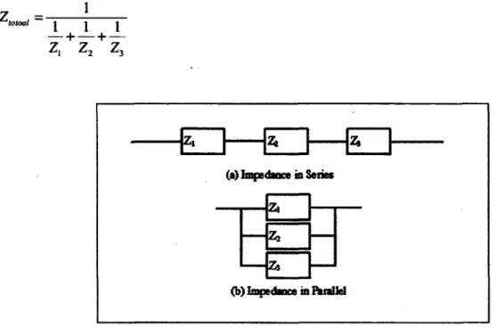
Fig. 15 A circuit unit of a resistor and a capacitor in parallel 37
Fig. 16 Nyquist plot of the circuit unit in Fig. 14 38
Fig. 17 A circuit unit of a resistor and a CPE in parallel 39
Fig. 18 Nyquist plot of the circuit unit in Fig. 17 39
Fig. 19 Schematic illustration of impedance in series and parallel 40 Fig. 20 Solution precursor preparation methodology for the nanopowder synthesis 45
Fig. 21 picture of the induction plasma system 46
Fig. 22 Induction plasma nanopowder synthesis system 47
Fig. 23 GNP powder synthesis system 48
Fig. 24 Induction plasma deposition system 51
Fig. 25 (a) mount and cup (b) the way to put the sample (c) cut and polished specimen 53
Fig. 26 Cutting machine 54
Fig. 27 Polishing machine 54
Fig. 28 Picture of the press 55
Fig. 29 Picture of the die 56
Fig. 30 Picture of the sample holder and mask for cathode-cathode symmetrical cell
production 56
Fig. 31 Schematic illustration of cathode-cathode symmetrical cell 57
Fig. 32 Picture of the unit for cell impedance test 58
Fig. 33 Picture of the bench test of the full cell 59
Fig. 34 Schematic illustration of the cell test system 59
Fig. 35 SEM picture of as-synthesized pure LSCF6428 63
Fig. 36 TEM picture of as-synthesized pure LSCF6428 nanopowder; magnifications of X50k
(A) and X200k (B).. 63
Fig. 37 Particle size distribution of as-synthesized LSCF6428 nanopowder 64
Fig. 38 SEM picture of calcined pure LSCF6428 nanopowder 64
Fig. 39 Particle size distribution of calcined (1000 °C for 2 h) LSCF6428 nanopowder 64
Fig. 40 SEM picture of as-synthesized GDC6/LSCF4 nanopowder . 65
Fig. 41TEM picture of as-synthesized GDC6/LSCF4 nanopowder; magnifications of XI 00k
(A) and X400k (B) 65
Fig. 42 SEM picture of calcined GDC6/LSCF4 nanopowder 66
Fig. 43 SEM picture of as-synthesized GDC3/LSCF7 nanopowder 66
Fig. 44 TEM pictures of as-synthesized GDC3/LSCF7 nanopowder; magnifications of XlOOk
(A) and X400k (B) 67
Fig. 45 SEM picture of calcined GDC3/LSCF7 nanopowder 67
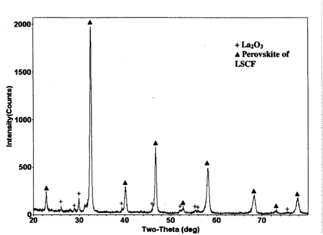
Fig. 46 XRD pattern of LSCF6428 nanopowder; (+), La2C>3 phase; (A), denotes perovskite
structure of LSCF 69
Fig. 47 XRD pattern of LSCF6428 nanopowder after calcination at 1000°C for 2 h; (A),
perovskite structure of LSCF 70
Fig. 48 TEM EDS local analysis figure of as-synthesized GDC6/LSCF4 nanopowder 71 Fig. 49 TEM EDS local analysis figure of calcined (1000 °C, 2h) GDC6/LSCF4 nanopowder
72
Fig. 50 TEM EDS local analysis figure of as-synthesized GDC3/LSCF7 nanopowder 72
Fig. 51 TEM EDS local analysis figure of calcined (1000 °C, 2h) GDC3/LSCF7 nanopowder
73
Fig. 52 EDS spectrum of the GDC (a), LSCF (b) and GDC/LSCF (c) phases (Cu is from the
mesh for TEM characterization); (•), residual Sr from neighbouring particles 74 Fig. 53 XRD pattern of GDC28 nanopowder synthesized by solution plasma spray; • fluorite
structure of GDC phase 76
Fig. 54 Phase changing of GDC6/LSCF4 nanopowder after calcinations, (+) fluorite structure
of GDC, (I) perovskite of LSCF; (a) as-synthesized; (b) calcined for 2 hours at 300 °C; (c)
calcined for 2 hours at 1000 °C 77
Fig. 55 XRD patterns of GDC6/LSCF4 nanopowder, (+) fluorite structure of GDC, (I)
perovskite of LSCF; (a) as-synthesized and (b) calcined nanopowders at 1000°C for 2h 77
Fig. 56 XRD patterns of GDC6/LSCF4 nanopowder, (+) fluorite structure of GDC, (I)
perovskite of LSCF; (a) as-synthesized and (b) calcined nanopowders at 1000°C for 2h 78
Fig. 57 SEM picture of GDP-GDC powder 80
Fig. 58 XRD pattern of GDP-GDC powder 80
Fig. 59 SEM surface picture of Sample #1; magnifications of X100 (1A) and XS.OOk (IB). 82 Fig. 60 SEM surface picture of Sample #2; magnifications of X100 (2A) and X5.00k (2B).. 83 Fig. 61 SEM surface picture of Sample #3; magnifications of XI00 (3 A) and X5.00k (3B).. 84 Fig. 62 SEM surface picture of Sample #4; magnifications of XI00 (4A) and X5.00k (4B). 85 Fig. 63 SEM surface picture of Sample #5; magnifications of X100 (5A), Xl.OOk (5B) and
X5.00k (5C) 87
Fig. 64 SEM surface picture of Sample #6; magnifications of X100 (6A), XI .00k (6B) and
X5.00k (6C) 88
Fig. 65 SEM surface picture of GDC6/LSCF4 SPS cathode; magnification of X250 90
Fig. 66 SEM surface picture of GDC6/LSCF4 SPS cathode; magnification of Xl.OOk 91
Fig. 67 SEM surface picture of GDC6/LSCF4 SPS cathode; magnification of X20.0k 91
Fig. 68 SEM cross section pictures of SPSGDC6/LSCF4 cathode 92
Fig. 69 SEM surface picture of GDC6/LSCF4 SolPS cathode at magnification of X100 93
Fig. 70 SEM surface picture of GDC6/LSCF4 SolPS cathode; magnification of Xl.OOk 94
Fig. 73 SEM cross sectional face picture of SolPS GDC6/LSCF4 cathode; magnification of
X500 95
Fig. 74 SEM surface picture of GDC3/LSCF7 SPS cathode; magnification of X250 97
Fig. 75 SEM surface picture of GDC3/LSCF7 SPS cathode; magnification of X200 98
Fig. 76 SEM cross section picture of GDC3/LSCF7 SPS cathode; magnification of X200 ....98 Fig. 77 SEM surface picture of GDC3/LSCF7 SolPS cathode at magnification of XI00 99
Fig. 78 SEM surface picture of GDC3/LSCF7 SolPS cathode; magnification of XI.00k 100
Fig. 79 SEM cross section picture of GDC3/LSCF7 SPS cathode; magnification of X120.. 100 Fig. 80 XRD patterns of deposited, post-heated SPS GDC6/LSCF4 cathode and
as-synthesized GDC6/LSCF4 nanopowder; (I), undetermined phase 101
Fig. 81 XRD patterns of SPS, SolPS GDC6/LSCF4 cathode and as-synthesized GDC6/LSCF4
nanopowder; (i ), undetermined phase; (O), substrate 102
Fig. 82 XRD patterns of SPS, SolPS GDC3/LSCF7 cathode and as-synthesized GDC3/LSCF7
nanopowder; (I), undetermined phase 103
Fig. 83 SEM cross section picture of SPS GDC6/LSCF4 cathode on LSGFM electrolyte after
bench test; the magnifications of X400 (A) and XI .5k (B) 105
Fig. 84 SEM cross section picture of SPS LSCF6428 cathode on LSGFM electrolyte after
bench test; the magnifications of X200 (A) and X400 (B) 106
Fig. 85 Nyquist plot of the cathode-cathode symmetrical cell [Holtappels and Bagger, 2002]
107
Fig. 86 Nyquist plot showing the results of EIS for symmetrical GDC6/LSCF4 cathode in air
at (a) 650°C, (b) 700°C, (c) 750°C, (d) 800°C 108
Fig. 87 Nyquist plot showing the results of EIS for symmetrical GDC3/LSCF7. cathode in air
at (a) 650°C, (b) 700°C, (c) 750°C, (d) 800°C 109
Fig. 88 Arrhenius plot of GDC6/LSCF4 (•) and GDC3/LSCF7(A) cathodes 109
Fig. 89 Schematic illustration of the contact problem in cathode polarization resistance test 111 Fig. 90 Picture of the coarse platinum current collector 111
Table 1 Technical characteristics of different fuel cells [Stambouli and Traversa, 2002] 6 Table 2 Perovskite-type oxide LSM: thermal expansion coefficient (TEC), electronic (ae), and
ionic conductivities (a;) in air [Fergus et al., 2008][Sun et al., 2010] 12
Table 3 Perovskite-type LaCoC>3-based oxide: thermal expansion coefficient (TEC), electronic
(oe), and ionic conductivities (CTO in air [Sun et al., 2010] 13
Table 4 Plasma parameters during SoIPS nanopowder synthesis 47 Table 5 GNP GDC powder synthesis precursor composition 49 Table 6 Plasma parameters during SPS/SolPS cathode deposition 51
Table 7 Polishing procedures 53
Table 8 EDS local composition analysis of synthesized nanopowders (Fig. 48-51) 75 Table 9 SPS varied experimental parameters (constant parameters are listed in Table 6) 81
Abreviations Definition
YSZ yttria stabilised zirconia GDC gadolinium-doped ceria
LSM strontium-doped lanthanum manganite
LSCF lanthanum cobaltite and ferrite based perovskite SDC strontium-doped samarium cobaltite
SSC strontium doped samarium
GDC28 Ceo.8Gdo.2O2
GDC19 Ceo.9Gdo.1O2
LSCF6428 Lao.6Sro.4Coo.2Feo.8O3
GDC/LSCF Ceo.8Gdo.2O2 mixed with Lao.6Sro.4Coo.2Feo.8O3 GDC6/LSCF4 60wt% Ceo.8Gdo.2O2 mixed with 40wt%
Lao.6Sro.4Coo.2Feo.8O3
GDC3/LSCF7 30wt% Ceo.8Gdo.2O2 mixed with 70wt% Lao.6Sro.4Coo.2Feo.8O3
LSGM8282 Lao.8Sro.2Gao.8Mgo.2O3 LSGFM Lao.8Sro.2Gao.7Feo.2Mgo. 103
Acronym Definition
AC Alternative current
APS Air plasma spraying
BSE Back scattered electron
CE Counter electrode
CPE Constant phase element
CTE Plasmas in complete
thermodynamic equilibrium
CVD Combustion chemical vapor
deposition
DC Direct current
EDS Energy dispersive X-ray
spectroscopy
EIS Electrochemical impedance
spectroscopy
GNP Glycine nitrate process
HT-SOFC High temperaure SOFC
IT-SOFC Intermediate temperature SOFC
LTE Plasmas in local thermodynamic
equilibrium
MEIC Mixed electronic-ionic conductivity
material
Non-LTE Plasmas that are not in any local thermodynamic equilibrium
OCV Open circuit voltage
PEMFC Proton exchange membrane fuel
cell
PPS Powder plasma spray
RE Reference electrode
SE Secondary electrons
SEM Scanning electron microscopy
SOFC Solid oxide fuel cell
SolPS Solution plasma spraying
SPS Suspension plasma spraying
TEC Thermal expansion coefficient
TEM Transmission electron microscopy
TPBs Triple phase boundaries
VPS Vacuum plasma spraying
WE Working electrode
Solid oxide fuel cells (SOFCs), a new power generation, having high energy conversion efficiency and low emission to the environment, are getting increased attentions as the Low-Carbon Economy becomes a much hotter issue in human being's lives. Years of efforts have been made to make it more widely used and commercialized. However, the target is not so easy to meet as there are two main barriers to overcome: high total costs of SOFC fabrications and short cell life-time. Therefore, developing cost effective fabrication methods and lowering the operating temperature are urgently needed. As a consequence, the concept of intermediate temperature SOFC (IT-SOFC) working at the temperature range of 600°C-800°C is proposed to replace the high temperature SOFC (HT-SOFC) working at 800°C-1000°C.
Lowering the operating temperature of the SOFC system enables a wide range of cheaper materials to be utilized and a prolonged cell life-time. However, it also brings several problems. When the operating temperature decreases, the ionic and electronic conductivities of the electrolytes and electrodes decrease exponentially, resulting in a huge energy loss. Currently, instead of using the traditional components for HT-SOFC, yttria-stabilised zirconia (YSZ) electrolyte, Ni/YSZ anode and strontium-doped lanthanum manganite (LSM) cathode, different cation-doped ceria, such as gadolinium-doped ceria (GDC) and samaria-doped ceria (SDC), are currently widely utilized for IT-SOFC electrolytes. They have a much higher ionic conductivity than YSZ and are free from the reactions with most of the cathode materials. As the oxygen surface exchange coefficient and oxygen diffusion coefficient values of LSM are relatively low, limited improvement of LSM cathode will be realized for the IT-SOFC. Therefore, current research interest is directed towards the lanthanum cobaltite and ferrite based perovskite (LSCF) and strontium-doped samarium cobaltite (SSC) having mixed and higher ionic and electronic conductivity, compared to LSM.
State of the art of nanoscale materials (< 100 nm) show a great potential for SOFC moving from HT down to IT. The nanomaterials have a spectrum of advantages for the SOFCs, such as the enhancement of the catalytic capacity [Hui et al., 2007], increased ionic and electronic conductivities [L. Jia, 2010]. Also nanoscale material is able to be sintered at lower
temperatures compared to the micron scale powders. This is very significant for the development of the IT-SOFC because the lowered sintering temperature enables one-step sintering temperature fabrication of an entire single cell, prevents some unpredicted reactions between components and leaves more porosity thus more active sites in the electrodes. In addition, by introducing nanostructures, much thinner (to micron size) and gas tight electrolyte can be realized. Also, the triple phase boundaries (TPBs) of the cathode can be enlarged by introducing mixed electronic-ionic conductivity material (MEIC) and functionally graded and nanostructures into the cathode fabrications.
As an alternative way to lower the fabrication cost, plasma spraying technology has been employed into the SOFC domain. Compared to the conventional wet processing method, plasma spraying processing technology provides numbers of advantages for the SOFC fabrication and developments. The processing temperature is sufficiently high for a wide range of materials can be used and the relative processing time can be reduced. In addition, plasma processes can save considerable experimental spaces, since the anode, electrolyte and cathode can be synthesized in the same piece of equipment. For cathode fabrication, compared to the only way of electrode powder preparation in conventional cathode processes, plasma spraying processes enables various feedstock materials in form of powder, solution and suspension to be used. Solution plasma spraying (SoiPS) enables directly nanostructured cathode coating formation from some ionic precursor solutions and suspension plasma spraying (SPS) enables the submicron-sized or nanosized particles to be conveyed into the plasma plume thus formation of nanosized or micro-sized splats or particles.
Induction plasma with its own intrinsic properties, e.g. clean environment, axial injection, large reaction volume and long residence time of the material in the plasma, is getting increased attentions. With this technology, thin and gas tight electrolyte is able to be deposited as well as porous and homogeneous electrodes. The concept of Ml induction plasma sprayed SOFCs using SolPS/SPS method was proposed and developed in the Centre de Recherche en Energie, Plasma et Electrochimie (CREPE), at University de Sherbrooke. Up to now, the problems of the consecutive spraying of different components and interface delaminations
during cell test are critical barriers against the development of the ftill sprayed cells since the interfaces between the components play quite an important role in the SOFC performance.
In this work, we mainly focused on induction plasma synthesises of cathode nanopowder materials and depositions of composite cathode coatings. Composite nanopowders of GDC/LSCF have been synthesized. The preliminary work of composite and nanostructured cathode coatings has been done. This work serves as the precursor of functionally graded cathode fabrications which will be carried out in the future. In this thesis, the Chapter 1 is the simple and quick view of the background of the SOFC material developments and plasma spray processing technology for SOFC fabrications; Chapter 2 is the literature review part. Firstly, the SOFC fundamentals, specific on the cathode material and structure developments are reviewed using recently published papers. Then the induction plasma spray for coating deposition and nanopowder synthesis along with the powder, solution, suspension plasma spray are reviewed. Finally, the fundamental theories of some core instruments for the sample characterizations are introduced; In Chapter 3, all the experimental equipment, operation and parameters related to this work are introduced; In Chapter 4, the results and discussions are presented. The results of the synthesized nanopowders are first discussed, followed by the results of the cathode coating produced by SPS and SolPS methods. In the following parts, brief results of the bench tests of full cells and impedance tests of the cathode are presented. In Chapter 5, the conclusion of all the work is made and the work planned to be carried out is presented.
REVIEW
2.1 SOFC Fundamentals
2.1.1 SOFC Principle and Applications
The generation of energy by clean, efficient and environmental-friendly means is now one of the major challengers for engineers and scientists as the increasing global energy consumption has had and will continue to have many detrimental effects on the earth's environment [Stambouli and Traversa, 2002]. Nowadays, the fuel cells are much in the news since they appear to be one of the most efficient and effective solutions to the environmental problems which we face today.
There exists a whole range of different types of the fuel cells, which differ in the nature of their electrolyte, as shown in Table 1. The first five types are characterized by a low to medium temperature of operation (50-210°C) and the latter three types are characterized by a high temperature of operation (600-1000°C). By far, most research groups concentrate on the proton exchange membrane fuel cell (PEMFC) and solid oxide fuel cell (SOFC) stacks.
Table 1 Technical characteristics of different fuel cells [Stambouli and Traversa, 2002] Types of the
fuel cell Electrolyte
Operating T (°Q Fwl Oxidant Efficiency Alkaline (AFC) Potassium hydroxide (KOH) 50-200 Pure hydrogen, or hydrazine liquid methanol Oa/Air 50-55% Direct methanol (DMFC)
polymer 60-200 Liquid methanol OVAir 40-55%
Sulfuric acid
(SAFC) Sulfuric acid
80-90 Alcohol or impure hydrogen O^Air 40-50% Proton-exchange membrane (PEMFC) Polymer proton exchange membrane 50-80
Less pure hydrogen from hydrocarbons or methanol Oj/Air 40-50% Molten carbonate (MCFC)
Molten salt such as nitrate,
sulphate, carbonates...
630-650
Hydrogen, carbon monoxide, natural gas,
propane, marine diesel
CO2/O2/A ir 50-60% Solid oxide (SOFC) Ceramic as stabilized zirconia and doped perovskite
600-1000 Hydrogen, natural gas or
propane 02/Air 45-60% Protonic ceramic (PCFC) Thin membrane of barium cerium oxide 600-700 hydrocarbons O^/Air 45-60%
A SOFC system is an energy conversion device that directly converts the chemical energy of a fuel gas (hydrogen, nature gas...) into electrical energy and heat without the need for direct combustion as an intermediate step. So it is not subjected to the Carnot thermal cycle limit and is able to provide much higher conversion efficiencies than the conventional thermomechanical method. The electricity is generated by the electrochemical combination of a gaseous fuel and an oxidant gas through electrodes and an ion conducting electrolyte. For example, as shown in Fig.l, a fuel such as hydrogen is fed to the anode, undergoes an
oxidation reaction, and releases electrons to the external circuit. Air is fed to the cathode, accepts electrons from the external circuit, and undergoes a reduction reaction. Then the oxygen ions flow from the cathode to the anode and then react with hydrogen ions to form water finally (see formulas [1]) with negligible emission. The electron flow in the external circuit from the anode to the cathode produces direct-current electricity. A SOFC can operate as long as the fiiel and oxidant are supplied to the electrodes.
Anode :H2+0~ —» H20 + 2e 1 - 2-Cathode i — O. + 2<? —^ O Overall : H2+ - 02 H20 2 [1]
SOFC
H, 00 <%:%
MS, a» H.0 0* • V' <J=3 02anode electrolyte cathode
Fig. 1 Diagram of the operation principle of a SOFC
The open circuit voltage of the system can be calculated through the Nernst equation [Sammes,
2006]:
E = E°+^lnP„ + ^ l n ^ 4 F 2 F 1 H,0
£° = -— [31 2 F
E° is the reversible voltage at the standard pressure and the operating temperature. AG0 is the
Gibbs free energy variation of reaction.
The SOFC technology has been developed for a wide range of power applications, from portable devices (50 W battery chargers), small power systems (e.g. 5 kW residential power or automobile auxiliary power units) to distributed generation power plants (e.g. 100-500 kW system). It can also be integrated with a gas turbine to form large (several hundred kW to MW) pressurized hybrid system [Ormerod, 2003]. Compared with other fuel cells, SOFCs have the advantages enabling them to be potentially competitive in the market from a material standpoint. The advantages are listed as follows [Stambouli and Traversa, 2002]:
1. SOFCs are the most efficient (fuel input to electricity output) fuel cell electricity generators currently being developed world-wide.
2. SOFCs are flexible in the choice of fuel such as carbon-based fuels, or natural gas due to its high operating temperature.
3. SOFC technology is most suited to applications in the distributed generation (ie, stationary power) market because its high conversion efficiency provides the greatest benefit when fuel costs are higher, due to long fuel delivery system to customer premises.
4. SOFCs have a modular and solid state construction and do not present any moving parts, thereby are quiet enough to be installed indoors.
5. The high operating temperature of SOFCs produces high quality heat byproduct which can be used for co-generation, or for use in combined cycle applications.
6. SOFCs do not contain noble metals that could be problematic in resource availability and price issue in high volume manufacture.
7. SOFCs do not have problems with electrolyte management (liquid electrolytes, for example, which are corrosive and difficult to handle).
8. SOFCs have extremely low emissions by eliminating the danger of carbon monoxide in exhaust gases, as any CO produced is converted to C02 at the high operating temperature.
Although SOFCs have a vast number of advantages, it is still not possible to be put into a wide use as a result of the high costs for fabricating and operating the SOFC system and the low durability of the cells. Therefore, intermediate temperature SOFCs (IT-SOFCs), working in the operation temperature range of 600-800°C, are developed to enable the realization of SOFC commercialization by widening the range of materials which are able to allow the cheaper fabrication, especially in relation to interconnects and balance-of-plant (BoP) components [Brett et al., 2008]. Lower temperature operation also allows more rapid start-up and shut-down, reduced degradation rate of the metallic components, improved durability, more robust construction through the use of compressive seals and metallic interconnects as well as the advantage of greatly simplified system requirements. On the other hand, when the operation temperature is lowered, the resistance and polarization loss in the electrolyte and electrodes are increased. As a consequence, currently, electrolyte with higher ionic conductivity and thinner layers are used to compensate the increase in ohmic loss and cathodes with mixed conductivities and developed micro/nanostructure are studied, which are reviewed in the following sections.
2.1.2 SOFC Cathode and Reaction Mechanism
Generally, the three components, anode, electrolyte and cathode, working in the SOFC system are required to be temperature tolerant and electrochemically compatible with other components. Due to the high temperature and all-solid state nature of the components, the thermal expansions of each material composing the stack must be as similar as possible. Therefore, the mechanical fracture and layer delaminations can be effectively avoided. The electrolyte is required to be gas tight in order to prevent the fuel from meeting the oxidant and
the cathode must be stable in the oxidizing atmosphere as well as the anode must be stable in the reducing atmosphere.
In a SOFC system, the cathode is the place where pure oxygen or oxygen from air is reduced. The electrochemical processes going on in the cathode are composed of different bulk and surface steps. The elementary reactions taking place in the overall electrode reaction are concluded as follows [Sun et al., 2010]:
1. The reduction of O2 molecules involving adsorption, dissociation, reduction and incorporation of O2" into the lattice of the cathode material, as described by the following
equation:
02 + 2V0** + 4e~ = 20*o [4]
2V" is a vacant oxygen, and Ox0 is an oxygen ion.
2. Ionic transport through the porous cathode toward the electrolyte
3. O2" ion jumping into the electrolyte lattice
As indicated in the equation, the oxygen reduction can only take place where oxygen, oxygen ion conduction and electron conduction contact with each other. These places are also called triple phase boundaries (TPBs). In a cathode with only electronic conductivity, the TPBs can be simply illustrated, as shown in Fig. 2. In the porous cathode, adsorbed oxygen is formed from the oxygen gas according to a dissociative adsorption step which occurs on the pores walls. If there is a breakdown in connectivity in any one of the three phases, the reaction cannot occur [Adler, 2004]. Therefore, the reasonable way to improve the electrochemical performance of the cathode is to utilize the cathode materials with both high ionic and electronic conductivities as well as to optimize the micro/nano structure of the cathode to enlarge the TPBs.
Catalytic Electrode
- Particles
Fig. 2 Schematic illustration of TPBs in cathode with only electron conductivity [O'Hayre et
al., 2005]
Based on thin electrolyte, overall loss of the cell is generally dominated by the loss on the cathode. That is because of the high-activation energy and slow-reaction kinetics for oxygen reduction reactions, compared to the hydrogen oxidation reactions. It is noted that the cathode polarization loss can be as high as 65% of the total voltage loss in the IT-SOFC [Koyama et
al., 2000]. Therefore, to develop the SOFC cathode is an important part in the whole
IT-SOFC system development.
2.1.3 SOFC Cathode Materials and Electrochemical Properties
Recently, there are two commonly used types of materials for SOFC cathodes. One is lanthanum manganite-based perovskites, traditionally used for the SOFC working at high temperature from 800°C to 1000°C. Another is lanthanum cobaltite and ferrite perovskites, usually used for the IT-SOFCs.
Undoped LaMnOa is orthorhombic at room temperature and present an orthorhombic/rhombohedral crystallographic transformation at around 600°C. This is the result of the oxidation of some Mn3+ to Mn4+ ions [Fergus et al., 2008]. This material has the
conductivity of LaMnCh can be improved by doping a lower valence ion to either A or B site. For instance, by substituting La3+ places with divalent cation dopants Sr2+, the electronic
conductivity of the material can be enhanced. Currently, Lai.xSrxMn03 (LSM),
strontium-doped lanthanum manganite, is the most popular and traditional cathode material for zirconia based SOFCs working in the operation temperature range of 800-1000°C. Its electronic conductivity is from 200 to 300 Scm"1 at 900°C and stable with YSZ (Yttria-stabilized
zirconia) up to 1200°C. However, LSM has quite low ionic conductivities, lO^-lO"7 Scm"',
even at the 900-1000°C temperature range. Some properties of LSM with different compositions are shown in the Table 2.
Table 2 Perovskite-type oxide LSM: thermal expansion coefficient (TEC), electronic (ae), and
ionic conductivities (Oi) in air [Fergus et al., 2008][Sun et al., 2010] Composition TEC (*10"° K"1) T(°C) <je (Scm1) CTi (Scm1)
Lao.95Sro.o5MnC>3 11.7 900 1.10*10''
Lao.9Sro.iMn03 9.9 1000 2.09* lO^
Lao.gSro.2Mn03 11.8 900 300 5.93*10'
LaojSrojMnOs 11.7 800 240
Lao.6Sro.4MnC>3 13 800 130
Compared to the LaMnCb-based cathode, the lanthanum cobaltite perovskite (LaCoCb) has higher electronic and ionic conductivity, shown in Table 3. Like LaMnC>3, LaCoC>3 shows intrinsic p-type conductivity, and has a big oxygen deficiency at high temperature [Ormerod, 2003]. Also the conductivity can be enhanced by doping a divalent cation, such as the Sr2+, on
the lanthanum site. However, the disadvantage of LaCoC>3 is its thermal expansion coefficient, which is much higher than the normal electrolyte material. It is easy to lead to a mismatch between the cathode and electrolyte. By substituting iron on the cobalt site, the TEC of the material can be reduced and the outcome material, Lai.xSrxCoi.yFeyC>3, is the well-known cathode material for IT-SOFC, The TEC of Lai_xSrxCoi.yFey03 decreased with the increased
content of the iron composition [Maguire et al., 2000]. In addition, this material provides a significant enhancement in the total conductivity and electrochemical activity. Nevertheless, this material reacts with YSZ to form SrZrCb insulating phase at temperature as low as 800°C [Jiang, 2002]. Therefore, in the case of YSZ electrolyte, doped ceria, such as GDC (gadolinium doped ceria) is used as an interlayer to separate the LSCF cathode and YSZ
electrolyte, avoiding reactions. In addition, since GDC exhibits higher ionic conductivity than YSZ, it recently became the typical electrolyte material in the case of LSCF cathode.
Table 3 Perovskite-type LaCoC>3-based oxide: thermal expansion coefficient (TEC), electronic (ae), and ionic conductivities (o;) in air [Sun et al., 2010]
Composition TEC (*10" K1) T(°C) ae (Scm"1) aj(Scm"')
Lao.8Sro.2CoC>3 19.1 800 1220 Lao.6Sro.4CoC>3 20.5 800 1600 0.22 Lao.8Sro.2Coo.8Feo.2O3 20.1 600 1050 19.3 800 1000 4*10"z Lao.8Sro.2Coo.2Feo.8O3 15.4 1000 125 14.8 800 87 2.2* 10"3 Lao.6Sro.4Coo.8Feo.2O3 21.4 800 269 0.058 Lao.6Sro.4Coo.2Feo.8O3 15.3 600 330 8*10"3 Lao.4Sro.6Coo.2Feo.8O3 16.8 600
Currently, nanomaterials in particular are of great interest for SOFC cathodes due to their potential to increase the cell performance, for the reason that the nanomaterials with dimensions down to atomic scale (10"9 m) present improved physical, chemical and
mechanical properties. A feature of these materials is the high fraction of atoms that reside at grain boundaries and grain surfaces, significantly enhancing the chemical activity and also the electrical conductivity [Hui et al., 2007]. Furthermore, compared with micron-scaled powders, the nanopowders can be sintered at a lower temperature, which prevents the unnecessary chemical reactions and keeps more porosity and more active zone that both facilitate gas diffusion and electrochemical reactions. By using nanomaterials, the homogeneity of micro-nano structure distribution is enhanced as well as the mechanical properties and gas passage through electrodes can be increased. This results in the formation of very homogeneous films (10- 15 jim) [Singhal and Dokiya, 2003].
2.1.4 SOFC Cathode Processing Methods and Cathode Electrochemical Performance
From a general point of view, enhancing the conductivities of the cathode materials and optimizing cathode microstructure are key for producing cathodes with better electrochemical performance. The way to enhance the ionic conductivity of the cathode material is to add a second phase, such as the electrolyte phase, into the original cathode material. By doing this, the ionic conductivity of the cathode can be enhanced and the TEC mismatch between the cathode and electrolyte can be effectively eliminated. According to the TPB model, the way to enlarge the TPBs is to employ novel cathode structure. It has been demonstrated that nanostructured electrodes with significantly high surface area offer superior electrochemical properties as long as sufficiently large pore size and enough porosity are provided [Liu et al., 2004]. Recently the concept of functionally graded materials (FGM) was also introduced to fabricate SOFC components. Instead of an abrupt change in composition or microstructure between the two materials, FGM have a graded interface at which the composition gradually changes form one material to another, thereby avoiding delaminations during thermal cycling [Hart et al., 2002]. In addition, the graded microstructure can facilitate the transportation of the oxygen so as to lower the cathode polarization resistance when it works in a SOFC.
For IT-SOFC fabrications, number of researchers focused on the mixed materials of GDC/LSCF. Various mass concentrations of GDC or LSCF as well as altered microstructures were applied to the cathode coatings production. It is hard to give a definite answer to the question of which GDC concentration for the composite materials is the best, since the fabrication methods were not identical. However, the experimental parameters, material mass concentrations as well as the micro/nano-structures are able to be optimized according to each fabrication technology and give some hints to other relative researchers. By using screen printing technique, Leng and et.,al [Leng et al, 2008] obtained GDC19/LSCF6428 (60:40wt%) composite cathode with the lowest polarization resistance of 0.17 Qcm2 at 600 °C, 7 times
lower than the pure LSCF cathode. As the author discussed, increasing the content of GDC from 40 to 60 wt%, the GDC19/LSCF6428 composite cathode showed more homogeneous pore structure and distribution, smaller particle size and less particle agglomeration. Whereas,
Murray showed the lowest polarization of 0.33 Qcm2 was achieved at 600 °C for
GDC28/LSCF6428 (50/50wt%) composite cathode, 10 times lower than pure LSCF cathode, using slurry spin coating [Murray et al., 2002]. Also he indicated the increasing GDC content from 0 to 50wt% resulting in a continuous decrease in the cathode polarization resistance. Furthermore, in Dusastre and Kilner's work [Dusastre and Kilner, 1999], GDC19/LSCF6428 cathode produced by slurry printing presented the lowest interfacial resistance of 1 Qcm2 at
590°C when concentration of GDC was 30 wt%. The resistance was 4 times smaller compared to pure LSCF cathode. The authors also noted that the porosity of the composite electrode was an important factor to determine the optimum composition and to achieve the best electrochemical performance for composite cathode materials. In CREPE research group at University de Sherbrooke, Bouchard et al., have deposited pure LSCF6428 and GDC28/LSCF6428 by SolPS and SPS respectively [Bouchard, 2006]. The pure LSCF6428 cathode presented a resistance of 1.3 Qcm2 at 600°C (0.35 Qcm2 at 700°C), which is lower
compared to the results provided by Murray, Dusastre and Kilner. Nevertheless, the GDC28/LSCF6428 composite cathode showed inversed results. The composite cathode has a larger polarization resistance than the pure LSCF cathodes and GDC28/LSCF6428 with the GDC weight percentage of 30% presented the largest polarization resistance, compared to the ones with 40wt% and 50wt% GDC. And the cathode with 40wt% and 50wt% GDC showed similar polarization resistances. As the authors noted, the big size GDC particles in the suspension precursor might result in the less inhomogeneous and porous structure compared to the pure LSCF cathode. Therefore, the composite coatings have larger polarization resistance. The author also mentioned that by altering the plasma parameters, the microstructure of GDC/LSCF cathode might be optimized.
Because of the concept of FGM, a wide spectrum of SOFC cathode research, thereafter, focused on the grading cathode fabrication. There are two main kinds of gradients in the cathode. One is the structure gradient and the other is the composition gradient. Due to the theoretical model of Deseure and et al. [Deseure et al., 2005], it was estimated that an increasing composition gradient results in a reduced ionic ohmic drop due to an optimized ionic migration process by enlarging cross sectional area. More experiments of different graded cathode designs show the advantage of the gradients. Liu and et al. [Liu et al., 2007]
fabricated a graded cathode with 10 jim inner layer of wet-coated LSCF6428 powders, made by citrate method, and 30 jim outer layer of wet-coated LSCF6428 powders, made by solid phase synthesis on the YSZ electrolyte. This coating exhibited an area specific resistance (ASR) of 1.115 Qcm2 at 950°C, lower compared to the single cathode 38.9 |im layer made
only by the solid phase synthesized LSCF6428 powder. It is related to the different structures of the coatings due to the different producing ways. In the case of composition gradient, at the temperature of 650°C, 50%LSC+50%SDC/25%LSM+25%LSC+50%SDC/50%LSM +50%SDC cathode made by ion impregnation method had 0.48 £2cm2, much lower compared
to 9.8 Qcm2 for the cathode with only LSM single layer with the similar thickness and
porosity [Xu et al., 2005]. Also, in Meilin Liu's research group, by using combustion chemical vapor deposition (CVD) method, they successfully fabricated a cathode having both the composition and porosity (showed in Fig. 3) gradients. The electrode-electrolyte interfacial polarization resistance was 1.62 Qcm2 at 600°C and 0.43 ficm2 at 700°C. And the single cell
performed impressively with the high power densities of 481 mW/cm2 at 800°C [Liu et al.,
2004]. In addition, by employing sol-gel/slurry coating techniques, Shaowu Zha and et al. have proposed 4-layer functionally graded cathode (shown in the Fig.4) with the polarization resistance of 0.21 Qcm2 at 700 °C [Zha et al., 2005]. 5-layer cathodes consisting of LSM and
YSZ (LSM/YSZ) and 9-layers cathode with additional layers made from LSM, LSCo and YSZ (LSM/LSCo/YSZ) have been studied utilizing spray painting method by Holtappels and C. Bagger [Holtappels and Bagger, 2002]. They have demonstrated that these two types of cathodes presented improved electrochemical performances compared to that of the conventional double layer cathodes. Furthermore, using slurry painting, N. T. Hart and et al. did the comparison between functionally graded cathodes by changing the material of one interlayer from LSM/YSZ to LSM/GDC [Hart et aL, 2002]. And the results showed the benefits of the graded cathodes with LSM/GDC interlayer were over the ones with LSM/YSZ interlayer, especially at the lower operating temperature.
30% LSM/30% LSC/40% ODC 60% LSM/40% GDC
60% LSC/40% GDC
YSZ electrolyte
60% NiCtf40% GDC
Fig. 3 Schematics of the functionally graded SOFC configuration [Liu et al., 2004]
IQOHLSCi'
ftinctionally • graded
cathode
, . YSZ electrolyte
Fig. 4 Schematics of the functionally graded cathode fabricated by Zha et al. [Zha et al., 2005] As listed above, numbers of graded cathodes have been fabricated by various technologies. The results showed the cathode performance is pretty sensitive to the composition and the structure of the coating. Using LSCF and GDC instead of LSM and YSZ could usually result in lower cathode polarization resistance. However, up to now, it is still difficult to standardize the graded cell configuration. Since the performances of the cathodes depend on many factors, such as fabrication technology, electrochemical test system, cathode microstructures... Almost every research group has their own streamline to fabricate the cell with the homemade test systems. Therefore, it is quite hard to have a standard recipe, even for the same fabrication technology. However, as mentioned above, according to a particular fabrication technology, it is always possible to find better optimized parameters and procedures. Take the induction plasma spray technology for instance. Feeding system, spraying distance, the atomization property of the probe and so on, can have strong influences on the cathode microstructures, namely the electrochemical properties.
2.2 Plasma Fundamentals
2.2.1 Plasma Concept
In summary, plasma is a medium containing lots of charged particles governed by electromagnetic forces. Plasma is a quasineutral gas of charged particles which possess collective behaviour. Plasma is the term used in physics to designate the fourth state of matter (exists in the sun and the stars, in space, etc.), apart from the solid, liquid, and gas state. Fig. 5 presents schematically the ranges of temperature, or particle energy of the four forms of matter in nature (the temperature of plasma reflects only the energy of the heavy particles).
I I i i I i m l I » . I m l > » i
10
210®
to
410
5Temperature (°K)
1 1 » « I i m l I » t I i i l l 1 » 1 j 1 1 1
0.01
0.1
1
10
Particle Energy (eV)
Fig. 5 State of matter versus temperature [Grill, 1994]
A plasma is usually obtained when sufficient energy, higher than the ionization energy, is added to atoms of a gas, causing ionization and production of ions and electrons. In a gas, a
plasma is usually excited and sustained by providing to the gas electromagnetic energy in different forms: direct current, radio frequency, microwaves, and so on. Plasma is often referred to as gas discharge because the most common way to produce plasma is by passing an electrical discharge through the gas. A plasma can also be obtained when high-density energy is provided to a liquid or a solid to cause its vaporization and ionization.
2.2.2 Plasma Type and Applications
The plasma state exists in the cosmos or is created under unique conditions for specific purposes. It is customary to classify this state in terms of electron temperatures and electron densities, as shown in Fig. 6. The plasma density, ne, spans the range between 1 and 1020 cm"3,
while the electron temperature, Te, can vary between 10"2 and 103 eV.
m DKtm OiMtty UTS)
Taking into account the wide ranges of parameters, the plasmas can be classified into several categories: CTE plasmas (plasmas in complete thermodynamic equilibrium), LTE plasmas (plasmas in local thermodynamic equilibrium) and non-LTE plasmas (plasmas that are not in any local thermodynamic equilibrium). CTE is related to uniform plasma, in which chemical equilibrium and all plasma properties are unambiguous functions of temperature. This temperature is supposed to be homogeneous and the same for all degrees of freedom, all components, and all possible reactions. However, plasma in CTE conditions cannot be practically realized in the laboratory. To imagine CTE plasma, one should consider a plasma with a volume so large that its central part is homogeneous and not sensitive to boundaries. Unlike CTE plasmas, the LTE plasmas are locally in equilibrium similar to that described for CTE with a single temperature T, which can differ from point to point in space and time. Thermal plasma is commonly considered as LTE plasmas. Non-LTE plasmas are also known as cold plasma because of the low temperature of the heavy species. Both of the LTE and non-LTE plasmas are both produced for research or manufacturing purpose.
Thermal plasmas that approach a state of LTE have the temperatures around 104 K with
electron densities ranging from 1021 to 1026 m"3. An increase of pressure in the plasma lead to
more frequent collisions between the electrons and the heavy species thus the pressure in the system increases toward to atmospheric pressure, as a result, the two subsystems tend to reach the same thermodynamic equilibrium. Normally, the temperature of the gas in the center of these plasmas can reach temperatures in the range of 20,000-30,000 K.
For the cold plasmas, the system is in low-pressure discharge, so the thermodynamic equilibrium cannot be reached, even at a local scale, between the electrons and the heavy particles. In this kind of plasmas, the temperature of the electrons is much higher than that of the heavy particles. The electron can reach temperatures of 104-105 K (1-10 eV), However, due
to the very low electrons' density and heat capacity, the amount of heat transferred by the electrons to the gas and to the walls of the container is so small that the temperature of the gas can be as low as room temperature.
Both of the thermal plasmas and cold plasmas have many applications in the research area or human's life environment. Thermal plasma technology can be applied to the area of material processing and waste material treatment [Boulos, 1991]. For instance surface modification and plasma spraying for depositing coatings, nanopowder synthesis and plasma chemical synthesis of ultrafine and high purity materials. Because of the nonequilibrium properties and ability of reacting with the gas at a relative low temperature, cold plasma can be used for microelectronic devices fabrication and also for coatings. Thermal plasmas are used for the material processing at CREPE of Universite de Sherbrooke.
2.2.3 Induction Plasma Technology
Induction heating has become an advanced technology after hundred-year development. The cardinal principle of induction heating is that a conductive metallic piece inside a high-frequency coil is "induced" before being heated to a high temperature. While for induction plasma, the medium, such as gas, is induced before it reaches the plasma state when the temperature is high enough.
A plasma torch is a device designed to heat gases to very high temperatures by taking advantage of the high conductivity of an ionized gas [Reed, 1961]. An induction plasma torch is the core of induction plasma technology, which contains three essential parts: a coil, a confinement tube and gas distributors. Fig. 7 shows the configuration of a ceramic tube R.F. induction torch developed at CREPE of the Universite de Sherbrooke [Boulos, 1992]. The ceramic tube has an internal diameter of 35-70 mm and a length of 150-200 mm. It is water-cooled and used to confine the plasma. The tube is surrounded by a three- to five-turn induction coil connected to the RF power supply through the "tank" circuit. The head of the torch, namely gas distributor, is responsible for the introduction of different gas streams into the discharge zone. Generally, there are three gases passing through the torch head. These three gas streams are named carrier gas, central gas and sheath gas, respectively, according to their distances from the center of the coil. The carrier gas is responsible for conveying the precursor into the plasma through an atomization probe. The central gas is used to form the plasma while the sheath gas is used to stabilize the plasma discharge. Besides, the sheath gas
keeps the plasma centered and away from the walls in order to keep them cool. Normally, sheath gas also participates in the chemistry reaction, providing the reducing or oxidising environment.
The R.F. induction plasma power is supplied by an oscillator frequency in the range of 2-4 MHz for low and intermediate power units (<100 kW), or 200-400 kHz for high powder (100
t
kW) units used in larger installation. The minimum power to sustain an induction plasma depends on the pressure, frequency and gas composition. All the plasma conditions including chamber pressure, gas flow rate and power can be controlled by the control console of the system. Another important part of the torch is the exit nozzle. By altering the nozzle diameter, the rates of plasma jet can thereby be changed according to the different density requirements of the deposited coatings [Boulos, 1992].
Following the evolution of the induction plasma technology in the laboratory, it exhibits distinctive advantages: POWOER+CARRER GAS SHEATH GAS 'TORCH IOOV INDUCTONCOH PLASMA CONPHHeUQ TUIE
1. Without the problem of erosion or contamination since there are no electrodes, compared with the conventional DC plasmas.
2. The possibility of the axially feeding precursors (solution, suspension and powder), which overcomes the difficulty in exposing the materials to the high temperature plasma.
3. The possibility of selecting versatile chemistry to work in reductive, oxidative, or even corrosive environment.
4. The possibility of complete reaction because of its relatively long residence time of the precursor in the plasma plume (1 ms-100 ms).
5. Relatively large plasma volume.
With these advantages, the induction plasma has been used in several industrial and research aspects. One of the most successful is in the nano-material processing, which is now carried on in our lab with radio frequency generated induction plasmas.
2.2.4 Induction Plasma Spraying
Currently, the process of the SOFC components and the fabrication of entire cells can be mainly categorized into the conventional processing, represented by "Wet Powder Processing," and the new processing method characterized by "Deposition Processes Making Use of Thermal Plasma Spray". The "Wet Powder Processing", including tape casting, screen printing and sintering steps, needs high processing temperature and relatively long periods. The long processing time leads to the material and structure alterations and hence limits the selection of the materials. As one new technique, plasma processes are not only time efficient, generally without or with only slight post-processing of the products, but also cost efficient. A large number of materials can be utilized to produce the SOFC components with controlled composition and porosity. Cheap substrates can be used since the deposition cost is relatively low and short in time [Henne, 2007][Tekna Plasma Systems Inc., 2009]. Therefore, the plasma technology gets increasing attentions on the way to the commercialization of SOFCs.
Plasma spraying, as part of thermal spraying, is a material processing technique for producing coatings and free-standing parts using a plasma jet. Because of its high temperature, any
![Fig. 2 Schematic illustration of TPBs in cathode with only electron conductivity [O'Hayre et al., 2005]](https://thumb-eu.123doks.com/thumbv2/123doknet/5424833.126900/30.924.283.698.137.389/fig-schematic-illustration-tpbs-cathode-electron-conductivity-hayre.webp)
![Table 3 Perovskite-type LaCoC >3 -based oxide: thermal expansion coefficient (TEC), electronic (a e ), and ionic conductivities (o;) in air [Sun et al., 2010]](https://thumb-eu.123doks.com/thumbv2/123doknet/5424833.126900/32.924.136.802.297.508/table-perovskite-lacoc-thermal-expansion-coefficient-electronic-conductivities.webp)