To cite this document: Wang, Xuan and Pommier-Budinger, Valérie and Gourinat, Yves A Specific Methodology of Creep Compensation for piezoelectric Actuators by Open-loop control. (2012) In: International Conference on Mechanical Engineering, Materials and Energy (ICMEME 2012), 26-27 Oct 2012, Dalian, China.
O
pen
A
rchive
T
oulouse
A
rchive
O
uverte (
OATAO
)
OATAO is an open access repository that collects the work of Toulouse researchers and makes it freely available over the web where possible.
This is an author-deposited version published in: http://oatao.univ-toulouse.fr/
Eprints ID: 6640
Any correspondence concerning this service should be sent to the repository administrator: [email protected]
A Specific Methodology of Creep Compensation for Piezoelectric
Actuators by Open-loop control
Xuan Wang
1, 2, a, Valérie Budinger
3, band Yves Gourinat
1, c1Université de Toulouse, ISAE/DMSM, Toulouse 31055, France
2Civil Aviation University of China, College of Aeronautics Engineering, Tianjin 300300, China
3Université de Toulouse, ISAE/DMIA, Toulouse 31055, France
a[email protected], b[email protected], c[email protected]
Keywords: Creep, Relaxation, Piezoelectric actuator, Inverse model, Compensation, Open-loop
control
Abstract. Piezoelectric actuators exhibit creep behavior in open-loop operation, which may lead to
unaffordable errors in high precision static positioning systems. An inversion-based compensation strategy by open-loop control is presented for reducing creep effect. The approach utilizes a nonlinear viscoelastic model to portray creep phenomenon, which consists of a linear spring, a nonlinear dashpot and a series of nonlinear Voigt elements. It is shown that for the presented creep model the step responses are very similar to the piezoelectric actuators. In order to compensate creep effect, a concept of voltage relaxation in piezoelectric actuators is proposed. And the voltage relaxation model tantamount to the inverse creep model is derived using a PID closed-loop control system. Experimental results prove that, by insertion of voltage relaxation model in open-loop operation, creep effect is attenuated markedly in piezoelectric actuators.
Introduction
Piezoelectric actuators, with their high resolution, fast response, high stiffness, no backlash, and no friction, are commonly used in a variety of applications such as microelectromechanical systems (MEMS), ultra-precision positioning, active structural vibration and shape control [1-4]. However, piezoelectric actuators also exhibit adversary nonlinear effect including creep, which can be seen as a slow drift of the displacement of piezoelectric actuator responding to a constant applied input voltage [5]. For example, the creep effect can cause loss in precision which becomes significant when positioning is required over extended periods time [6].
Because the closed-loop compensation methods for creep effect may not be easy to implement in many cases due to the high cost and space requirements of displacement sensors, the open-loop compensation method attracts more attention [7-10]. This method is to establish a model which can portray the creep phenomenon of piezoelectric actuators and then reshape the input voltage based on the inversion of the model [10]. Hence, many models have been developed for characterizing the creep behavior, including the logarithmic model [5, 11], LTI model [5] and nonlinear viscoelastic model [12]. Among these models, except LTI model [5] that can be directly inversed, the other models [11, 12] are difficult to be inversed for control purpose due to the nonlinear function existing in the models.
In this paper, a nonlinear viscoelastic model is adopted to describe creep behavior. It is shown that for the presented creep model the step responses are very similar to the piezoelectric actuators. To circumvent the difficulty of inversing the creep model, a concept of voltage relaxation in piezoelectric actuators is proposed in this contribution. And a PID closed-loop control system is developed to derive the voltage relaxation model tantamount to the inverse creep model. Finally, experimental results prove that, by insertion of voltage relaxation model in open-loop operation, creep effect is attenuated markedly in piezoelectric actuators.
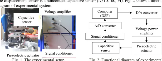
All the parameters of the creep model are identified from experimental results. The experimental setup is shown in Fig. 1. A ring-type piezoelectric actuator (NCE41, Noliac) is used as study object. The displacement sensor is a noncontact capacitive sensor (D510.100, PI). Fig. 2 shows a functional diagram of experimental system.
Fig. 1 The experimental setup Fig. 2 Functional diagram of experimental
system
Creep Modeling and Identification
Fig. 3 illustrates the typical response of piezoelectric actuators for a step input voltage. A nonlinear viscoelastic model is employed to characterize the creep response, as shown in Fig. 4, in which the linear spring corresponds to an instantaneous elastic response and the single nonlinear dashpot relates to the steady creep component for constant voltage, in addition, the series of nonlinear Voigt elements represents a transient component. Here it is considered that there is no instantaneous elastic component, as the subsequent expansion is slower than the initial fast transient by orders of magnitude [12].
Fig. 3 Experimental creep response Fig. 4 The phenomenological model for creep
The creep model shown in Fig. 4 can be described in state-space form using the n transient components and the steady creep component as states:
1 1 2 2 1 1 1 2 2 2 =- + =- + . =- + = n n p v v p v v p v n v n n m s V ε λ ε λ r μ V ε λ ε λ r μ V ε λ ε λ r μ V ε η (1)
And output equation is: Time (second) Posit ion Voltage (V ) Instantaneous elastic response Steady
creep Transient creep
Capacitive sensor Piezoelectric actuator Voltage amplifier Signal conditioner Computer (DSP) D/A converter Voltage power amplifier Signal conditioner Capacitive sensor Piezoelectric actuator A/D converter Final value Steady portion of creep Transient portion
1 2
= + + + + .
n
v v v s
ε ε ε ε ε (2) In the above equations, λi and ri are respectively characteristic frequencies and weights [12]; ε is the
position voltage obtained from capacitive sensor shown in Fig. 1. After substituting the integration of Eq. 1 into Eq. 2 the creep model can be described as:
-
=1 = 1- i + . p n m λ t i i V V ε r e t μ η
(3) The model parameters consisting of the n characteristic frequencies λi and their weights ri, andthe parameters from voltage power laws, namely, p, m, μ and η. They are estimated from a series of step voltage responses, as shown in Fig. 5. First, the steady rates of creep are estimated using a regression line fitted to the last portion of the step response shown in Fig. 3. And the slopes of the regression lines corresponding to steady constant rates are fitted to the voltage power law in the last equation of Eq. 1 using another linear regression, as depicted in Fig. 6 that shows the good fitness of the parameters from voltage power laws. Second, extracting the steady component of creep from the overall creep response, only the transient components shown in Fig. 3 with zero rates and final values are left for parameter estimation. Using linear regression again, the final values of the transient components depicted in Fig. 3 are fitted to the voltage power law in the first n equations of Eq. 1. The fitness is very good as shown in Fig. 6. Third, for obtaining the characteristic frequencies and their weights, the normalized transient response of 220 V input is chosen as the reference one. Four frequencies and their weights fitting very well with the reference response are found as a first approximation, resulting in a model of order five, via “Procedure X” [13], an iterative process that estimates characteristic frequencies and their weights from a step response. These parameters are further refined by employing a standard nonlinear least-squares fitting, as shown in Table 1. A comparison between measured responses to a set of constant voltages input in experiments and predicted curves employing the presented creep model as Eq. 2 is shown in Fig. 5, demonstrating the predicted curves fitting the measured responses very well.
Fig. 5 Responses to a series of input voltages and their predictions
Fig. 6 Fitness of power law parameter Table 1 Characteristic frequencies and weigths
Char. Freq. λ Weight r Char. Freq. λ Weight r
Proc. X Proc. X NLSQ NLSQ
0.1129 0.024 0.197 0.0706 0.2166 0.0495 1.1594 0.0282 1.0817 0.0388 2.4434 0.0261 10.8936 0.3755 17.7129 0.863
Voltage Relaxation Modeling
0 5 10 15 20 25 30 0 1 2 3 4 Time (second) Pos ition V ol ta ge (V ) predicted Measured 260V 220V 180V 140V 100V 60V 20V 0 100 200 300 0 0.005 0.01 Input Voltage (V) Sl op e ( V /s eco nd
) Slopes of Steady Creep
Measured Power law (V/η)m η=1.027e+4 m=1.3243 0 50 100 150 200 250 300 0 2 4 Input Voltage (V) Fi na l V al ue ( V
) Final Value of Transient
Measured
Power law (V/μ)p
μ=89.5333 p=1.0642
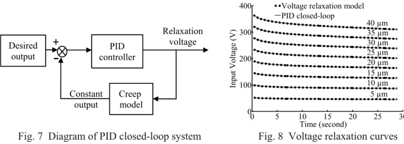
According to Eq. 3, ε (V, t) is not only the nonlinear function of time but also of the input voltage for the creep model. As a result, it is very difficult to derive the unique inverse model directly from the creep model mathematically. However, it is known that the inverse creep model should have the form of V(ε, t). Corresponding to creep, a slow drift of the displacement of piezoelectric actuator responding to a constant applied voltage, the form of inverse creep model V(ε, t) can be seen as the input voltage changes with a fixed displacement of piezoelectric actuator. Obviously, the relationship between creep and its inversion in piezoelectric actuator is analogous to the pair behaviors of creep and relaxation in viscoelastic material. Hence voltage relaxation, namely the pairing behavior of creep in piezoelectric actuators, is proposed to describe the inverse behavior of creep. That is to say, the problem of inversing creep model can be replaced by the issue of developing the voltage relaxation model of piezoelectric actuator. A PID closed-loop control system is developed using MATLAB to keep constant displacement. Fig. 7 shows the block diagram of the PID closed-loop control system that leads to a set of voltage relaxation curves can be obtained as depicted in Fig. 8.
From Fig. 8 and [13], the relaxation model can be presumed as:
-
=1 =1 =- 1- i - + + . a n b c a n τ t i i i i ε ε ε ε V f e t f ρ α β ρ
(4) The first two terms in Eq.4 is same as Eq.3 in form except the negative sign, so the parameters from displacements power laws, namely, ρ, a, α, b, and characteristic frequencies τi and their weights fican be estimated via the similar process of parameter identification in creep modeling. The parameters β and c from displacement power laws in the third term of Eq.4 can be identified using linear regression once again. Fig. 8 illustrates the very good agreement between the voltage relaxation curves obtained from PID closed-loop system and from the model.
Fig. 7 Diagram of PID closed-loop system Fig. 8 Voltage relaxation curves
Compensation in Open-loop
An open-loop control system for compensating the creep effect is developed as the cascade of voltage relaxation model and piezoelectric actuator as shown in Fig. 9.
Fig. 9 Open-loop control system for creep compensation
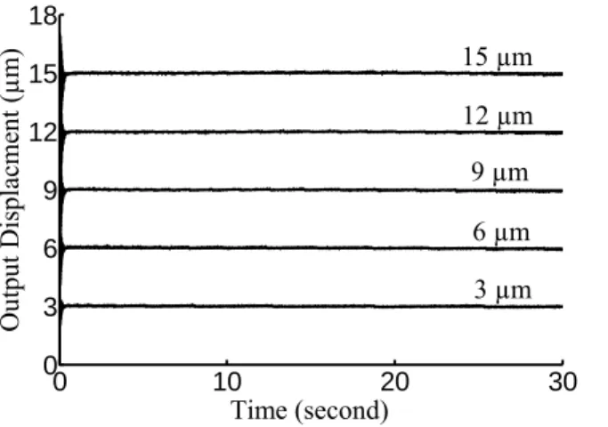
To evaluate the quality of creep compensation method, a set of step displacement inputs with 3 μm, 6 μm, 9 μm, 12 μm and 15 μm of amplitude is applied to piezoelectric actuator. Experimental results depicted in Fig. 10 demonstrate that the actual output displacements remain their desired
0 5 10 15 20 25 30 0 100 200 300 400 Time (second) Input Voltage (V )
Voltage relaxation model PID closed-loop 40 µm 35 µm 30 µm 25 µm 20 µm 15 µm 10 µm 5 µm Desired
output controller PID
Creep model Relaxation voltage
‐
+
Desired outputVoltage relaxation model (inverse creep model)
Piezoelectric actuator Output Reshaped input voltage Constant output
amplitudes. It can be seen that the creep phenomenon is attenuated significantly and effectively using the presented compensation strategy.
Fig. 10 Experimental step responses when using the presented creep compensation strategy
Conclusions
This paper presents an inversion-based open-loop control compensation strategy for reducing creep effect in piezoelectric actuators. A nonlinear viscoelastic model is employed to describe creep behavior. Modeling and parameters identification procedures are presented in detail. Due to the difficulties in deriving the inverse creep model, a concept of voltage relaxation that portrays the pairing behavior of creep in piezoelectric actuators is proposed. And the voltage relaxation model, namely the inverse creep model, is developed with the help of a PID closed-loop control system. By insertion of voltage relaxation model in open-loop operation, a set of step displacement inputs is applied to piezoelectric actuator. Experimental results show that the presented creep compensation method offers a very good reduction of creep.
References
[1] M.N. Ghasemi-Nejhad et al.: Journal of Thermoplastic Composite Materials, Vol.19 (2009) No.3, p. 309-352
[2] B. Mokaberi, A.G. Requicha: IEEE Transactions on Automation Science and Engineering, Vol.5 (2008) No.2, p. 197-206
[3] L. Gaul, J. Becker: International Journal of Engineering Science, Vol.47 (2009) No.11, p. 1193-1207
[4] S.K. Agrawal, D. Tong and K. Nagaraja: Journal of Intelligence Material Systems and Structures, Vol. 5 (1994) No.4, p. 514-521
[5] M. Osamah, El Rifai, and K. Youcef-Toumi: America Control Conference (MIT, Cambrige, MA, 2002), Vol. 5 (2002), p.3777-3782
[6] R.S. Robinson: Journal of Computer Assisted Microscopy, Vol.2 (1996) No.1, p. 53-58
[7] D. Croft, G. Shed and S. Devasia: Journal of Dynamic Systems, Measurement, and Control, Vol.123 (2001) No.1, p.35-43
[8] H. Janocha, K. Kuhnen: Sensors and Actuators A: Physical, Vol.79 (2000) No.2, p. 83-89 [9] Ru Changhai, Sun Lining: Sensors and Actuators A: Physical, Vol.122 (2005) No.1, p.
124-130
[10] T.J. Yeh, R.F. Hung and S.W. Lu: Simulation Modeling Practice and Theory, Vol.16 (2008) No.1, p. 93-110
[11] H. Jung, D.G. Gweon: Review of Scientific Instruments, Vol.71 (2000) No.4, p. 1898-1900 [12] H. Richter, E.A. Misawa, D.A. Lucca and H. Lu: Precision Engineering, Vol.25 (2001) No.2,
p. 128-137
[13] N.W. Tschoegl: The Phenomenological Theory of Linear Viscoelastic Behavior: An Introduction (Springer-Verlag, Berlin Beidelberg, Germany, 1989), p. 136-137
0 10 20 30 0 3 6 9 12 15 18 Time (second) Ou tpu t Dis pl acmen t (µm) 15 µm 12 µm 9 µm 6 µm 3 µm