HAL Id: hal-01250766
https://hal.archives-ouvertes.fr/hal-01250766
Submitted on 5 Jan 2016
HAL is a multi-disciplinary open access
archive for the deposit and dissemination of sci-entific research documents, whether they are pub-lished or not. The documents may come from teaching and research institutions in France or abroad, or from public or private research centers.
L’archive ouverte pluridisciplinaire HAL, est destinée au dépôt et à la diffusion de documents scientifiques de niveau recherche, publiés ou non, émanant des établissements d’enseignement et de recherche français ou étrangers, des laboratoires publics ou privés.
Embedded Network Combining CAN, ZigBee and
DC-PLC for Motorhome
Fabienne Nouvel, Hussein Kdouh
To cite this version:
Fabienne Nouvel, Hussein Kdouh. Embedded Network Combining CAN, ZigBee and DC-PLC for Motorhome. VEHICULAR 2015, Oct 2015, St JULIANS, Malta. �hal-01250766�
Embedded Network Combining
CAN, ZigBee and DC-PLC for Motorhome
Fabienne Nouvel IETR/INSA Rennes, France e-mail : [email protected] Hussein Kdouh IETR/INSA Rennes, France e-mail: [email protected]Abstract— Today, the number of motorhomes increases in
Europe and North America as they offer greater individual freedom. As motorhome users spend the most of their time in their confined area, it seems essential to develop new solutions that make their life easier. In order to meet the new needs of customers, a new centralized architecture of a control system based on ubiquitous wired and wireless solutions is studied in this paper. The objective of this study is to verify the feasibility of ubiquitous technologies in this original environment. Different measurements have been conducted on a motorhome using Controller Area Networks (CAN), ZigBee and direct current power line communications (DC-PLC). Results have shown that these technologies may be used in a future hybrid control system in a motorhome.
Keywords— Motorhome; Controller Area Networks; CAN; ZigBee; Power Line Communications;
I. INTRODUCTION
Recent results of motorhomes sales confirm the enthusiasm of people for this type of vehicles, especially in Europe and North America [1]. Motorhomes perfectly meet the needs of freedom, mobility and the wishes of autonomy that users seek. Otherwise, they may be an economic solution with respect to expensive hotel and trains reservation rates in touristic areas.
Motorhomes are similar to homes as they include a kitchen, a bathroom, sleeping facilities and a dining room. One can found several amendies such as refrigerator, gas cylinder, boiler, air-conditioner, folding step, and water (fresh, gray and black) tanks. Furthermore, similar electric installations can be found. Electrical equipments may be powered by different energy sources available in the motorhome, such as main and auxiliary house batteries, engine battery, solar cells and / or external alternative (AC) 230 V available in the camping areas.
Although today’s motorhomes have a broad array of choices to be connected to Internet, motorhomes do not use communication network to interconnect the equipments in the home area.
Camper van can be either considered as a vehicle or as a mobile home. If it considered as a vehicle, electronic units are nowadays connected by networks. Many standards are available, the most widespread are control area network (CAN), local interconnect network (LIN) and Flexray [2]. These networks reduce the number of wires while achieving
low to medium data rates and better reliability. However, these buses are placed in the motor area and mainly used for driving and automotive controls. Furthermore, they must be separated from the possible camper van “home network”, due to security levels.
If we consider it as a "mobile home", many technologies have been developed to make the home smart. The technologies include solution for building automation as well as the domestic control activities [3]. Furthermore, devices may allow remote access.
It seems to be interesting to combine networks used for control driving with solutions used for domestic tasks. Actually, all the amenities in camper van are manually controlled by the users or via separated control systems. Some control systems are proposed by manufacturers but these solutions are proprietary solutions and not easy to modified. In this paper, we propose to replace separated non connected control systems in a camping-car by a centralized control system. Another objective is to replace point to point connection using a specific wire by a communication network that will reduce the weight and number of cables. Proposed new architecture may be based on both on wired and wireless communications technologies that connect a central unit to the different amenities in the motorhome.
Among the possible solutions, CAN seems to be attractive as it is widely used both in automotive [4] and in a variety of industries including building, automation and manufacturing. Moreover, CAN has been already used to connect home appliances for smart home applications [5] [6].
We have also to consider the wireless solution in order to offer easy plug and play applications while achieving low cost. Among the technologies, ZigBee, an IEEE 802.15.4 standard-based solution defined by the ZigBee Alliance [7], was developed specifically to support sensing, monitoring and control applications. The ZigBee solution offers significant benefits, such as low power, robust communication and a self-healing mesh network. Common applications supported by ZigBee include: personal monitoring, security, access control and safety monitoring, home, building and industrial automation [7].
As many devices in the motorhome are powered by AC or DC power, another solution to consider reducing the number of cables is power line communication (PLC). There is a growing in interest for PLC, including smart grids, home networking and control, as well as automotive uses [8].
Hence, the proposed PLC technologies have been studied in cars and indoor environments, but they have not been tested in motorhome environment. Therefore, we will present in this paper the results obtained from different measurements in order to study the feasibility of these three technologies in motorhomes.
The remainder of this paper is organized as follows. Section 2 describes the functionalities and the architecture of the proposed control system. Section 3 deals with the CAN-based part of the system, including signals and messages definitions, network dimensioning and simulation and measurement results. Section 4 focuses on ZigBee tests conducted in the motorhome and presents the obtained results. Section 5 presents the results of PLC measurements and results. Finally, a conclusion is drawn in Section 6.
II. SYSTEM FUNCTIONALITIES AND ARCHITECTURE
The considered embedded control system must carry out several functionalities. We can cite according to the priority:
Measuring capacity, voltage and current of available energy sources (main and auxiliary batteries, solar cells) and switching between available energy sources Measuring the energy consumption of appliances
(refrigerator, TV, pumps, lights) Measuring weather data
Generating alarm when detecting an intrusion Turning on/off and controlling brightness of lights Exchanging with the environment through internet. We aim to develop a user-friendly control system that can accomplish these functionalities and possible supplementary ones. The system must provide high quality of service in terms of reliability, robustness, delays, and at the same time ensure the convenience and comfort of motorhome users.
To ensure the passengers’ convenience and comfort, a unique user interface based on embedded OS (Linux, Android) will then replace the different interfaces used currently for motorhome appliances. Passengers will simply send orders or
receive measurements to or from appliances by touching a user-friendly screen.
The second objective is ensuring reliable data communication between the central control unit and equipments. Different communication technologies exist in the market for this kind of applications. We have to select the best adapted solutions to our environment and applications.
The above mentioned functionalities may be categorized into three main categories: high level security, low level security and infotainment functionalities. The first two categories do not need high data rates but they must be secure, the frames are mainly orders or sensor measurements. However, infotainment functionalities, multimedia data, video surveillance or internet, necessitate high data rates.
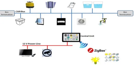
Therefore, we propose to combine different communication technologies with respect to considered functionalities. High level security functionalities will be accomplished using sensor and actuators connected to corresponding equipments and exchanging via a CAN bus to a central control unit. Low level security functionalities such as measuring weather data and controlling lights will be accomplished by ZigBee nodes. High data rates functionalities will be finally exchanged using PLCs without using additional wires. Figure 1 shows the general architecture of proposed control system and communication technologies used with respect to functionalities.
In order to verify the feasibility of these technologies, we have conducted several measurements in a motorhome provided by the motorhome manufacturer Autostar. The motorhome comprises two main parts. The sleeping compartment contains a fixed bed, a shower cubicle and a wardrobe. The living compartment includes a kitchenette area with a refrigerator, grill and sink. Below the floor of the camper, we can find other amenities such as water tanks and pump, gas cylinders, batteries and boiler. Following sections will describe the performed experiments and present the obtained results. We will begin with CAN measurements.
III. CANMEASUREMENTS
Most of system functionalities will be performed via the CAN bus, like monitoring water tanks, switching between energy sources, controlling air-conditioner and ventilator, etc. Several CAN nodes (each one connected to one or more equipment) will communicate to the central node in the camping car. The user interface will help the user to send orders and analyze measurements sent by sensors given by the other CAN nodes.
A. CAN Overview
CAN 2.0A/B is a network protocol developed for connecting the sensors, actuators, and controllers in a vehicle. CAN supports data rates from 5 kbps up to 1 Mbps, which allow the CAN network to be used to share status information and is available for real-time control. The medium access control (MAC) level uses the carrier sense multiple access/collision detection (CSMA/CD) protocol to access the network, using the field “Identifier” of the frame.
CAN allows multiple devices (referred to as “CAN nodes”) to connect to each other on a single bus. CAN nodes do not have strict master/slave roles. Instead, each CAN node may operate as a transmitter or receiver at any time. In reception, each node decides if the data is relevant by looking at the message frame's “Identifier”, which describes the content of the message.
B. System Design
The CAN bus functionalities are accomplished by sensors or actuators connected to corresponding equipments. A sensor (actuator) will send (receive) a digital signal to (from) the central CAN node via the CAN bus.
The first step in the network design was the definition of signals that will be exchanged through CAN messages and the identifiers between the central node and the appliances. A database of about 100 signals has been defined for the system.
The second step was the definition of CAN messages and the assignment of digital signals. One or several signals have been assigned to each CAN message. A total of 35 CAN messages/identifiers have been finally defined for the whole network. These messages can be categorized into four different categories:
Order messages are generated by the central node and contain an order sent to one or several actuators, such as opening or closing a gas cylinder. This type of message may be generated manually by the user when touching the screen, or automatically by the central node for security reasons, such as ordering the closure gas cylinders and folding the step when the motorhome starts moving.
Alert messages are automatically generated by CAN nodes to warn the central node about a special event, such as intrusion detections.
Sensing messages are periodically generated by CAN nodes and contain sensor measurements such as water tank levels, batteries voltages, and others.
Life sign messages are periodically generated by CAN nodes to ensure their connectivity to the bus. When a CAN node sends a life sign message, it waits for an acknowledgment from the central node. In absence of this acknowledgment, it repeats the transmission of the life sign message for a user-predefined maximum number of trials. If no acknowledgment is received, a CAN node will be considered disconnected from the bus and must stop sending its alert and sensing messages. However, receiving any type of message (acknowledgment or order message) from the central node will reactivate the CAN node.
As the identifier of a CAN message determines its priority on the bus, we have assigned to each message an identifier based on its priority in the application. Lowest identifiers (highest priority) have been assigned to order messages. The second, third, and fourth levels of priority have been assigned to alert messages, sensing messages and life sign messages respectively.
The third step is the network dimensioning, i.e., the estimation of number of CAN nodes in the network. In order to minimize the number of CAN nodes in the network, we have connected equipments that are nearly placed in the motorhome, to the same CAN node. For example, Gas cylinders and water tanks have been connected to one CAN node.
C. CAN Bus Simulation
To study the performance of our CAN architecture, we have used the development and testing software tool CANoe from Vector GmbH. CANoe is a versatile tool for the development, testing and analysis of entire Electronic Control Unit (ECU) networks as well as individual ECUs. It supports network designers, development and test engineers at equipment manufacturers and suppliers over the entire development process – from planning to the start-up of entire distributed systems or individual ECUs. CANoe supports CAN, LIN, FlexRay and other networks.
At the beginning, CANoe has been used to create simulation models which simulate the behavior of the CAN nodes. Over the further steps of nodes development, these models serve as the basis for analysis, testing and the integration of bus systems and nodes. This makes it possible to detect problems early and correct them. Graphic and text based evaluation windows are provided for evaluating the results [9].
The simulation procedure consists of developing all CAN nodes, exchanged signals and messages, and finally a GUI to simulate the central control node. CAN nodes have been firstly developed through Vector CAPL (CAN Access Programming Language) based on the C programming language. Using CANoe in combination with CAPL makes it possible to create custom tool applications with user defined behavior. Secondly, the database of CAN messages and
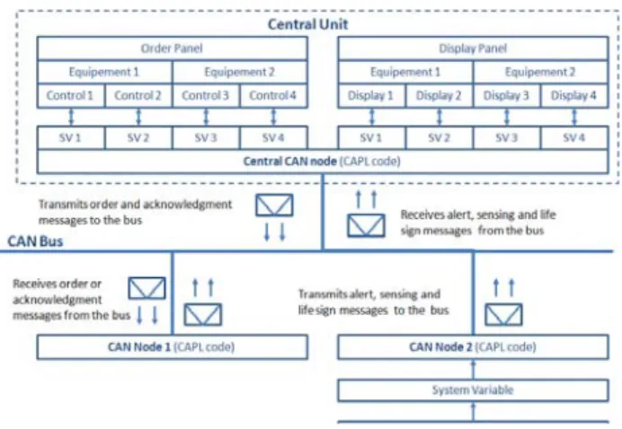
signals is recreated in Vector CANdb++ (which is a data administration program with which communication databases can be created and modified in the form of CAN databases) and added to the simulated bus. Signal generators have been added to generate random or predefined sensing values to the CAN nodes. Figure 2 explains the architecture of our CAN bus simulator using CANoe.
Figure 2. Architecture of the CAN bus simulator using CANoe.
Several simulations scenarios have been carried out to verify the correct behavior of individual CAN nodes (success and periodicity of CAN messages transmission) and the whole network (bus load and end-to-end delays). As stated before, this step helps us to detect problems early to prevent them in the implementation phase. Different data rates between 5 up to 1000 kbps and periods of data transmission, between 0.2 and 10 seconds, have been tested. In all simulation scenarios, all nodes send their CAN messages at the same time to simulate worst case scenarios.
By studying the simulation database and filtering messages by CAN node, we have found that all nodes can send successfully their CAN messages to the central unit for data rates higher than 50 kbps regardless the period of transmission. However, the bus load may reach values from 20 to 100% for rates less than 100 kbps. The maximum end-to-end delay, defined as the time between the generation of a CAN message by a CAN node and its reception by the central node, is less than 100 ms for all data rates higher than 30 kbps.
Using these results, a data rate of 500 kbps and a period of 1 second have been adopted in our application. For this scenario, a bus load of only 0.77% and a maximum end-to-end delay of 3.79 ms have been obtained. These values show that data traffic exchanged in our application is largely lower than the capacity of the CAN network. That proves also that possible adding of future supplementary functionalities, will not affect the performance of existing network. Simulation results motivate us to start the implementation step.
D. Implementation and Tests of CAN Nodes
Each CAN node has been developed using an ARM Cortex-M3 LPC1758 board from NXP Semiconductors which supports two CAN peripherals. A generic embedded C code
has been developed for all CAN nodes. A 4 bits local address represented by a 4 bits input to the microcontroller, has been assigned to each CAN node. It determines the part of the generic code to be executed to perform the node functionalities. Based on the CAN node address, different General Purpose Input Output (GPIO), serial ports and/or analog-to-digital converter pins are configured to exchange digital signals with connected sensors and actuators.
CANoe has been also used to test the behavior of the developed CAN nodes. Using a particular interface, CANoe provides the possibility of replacing one, several or all simulated nodes by real ones. The conducted test includes 3 real CAN nodes ( based on the LPC1758-microcontroller) and 4 simulated CAN nodes as well as the simulated central node. The interface CANcardXL allows mixing hardware and software running CANoe (on a laptop). In order to test the behavior of all CAN nodes, the test has been repeated several times. In each test, identifiers of simulated and real CAN nodes have been exchanged.
The CANcardXL interface is a hardware interface between the real bus and the simulated one. This hybrid network has been tested each time for 3.5 hours (12600 seconds) and each CAN node was sending its sensing message every one second and its life sign message every 15 minutes. The data rate was set to 500 kbps for all nodes.
By studying the database of exchanged CAN messages provided by the Trace window of CANoe, we have found that each CAN has sent 12600 sensing messages to the central node as well as 16 life sign messages, which means that all CAN messages have been successfully sent. Moreover, the period between two successive CAN messages was around 1 second (with several tens or hundreds of microseconds corresponding to the arbitration phase between CAN nodes trying to send at the same time).
A last experiment has been carried out without simulation using different hardware CAN nodes and a central node emulated thanks to an USB-MUX-4C2L board. Similarly, the results of this test have shown a frame transmission ratio equal to 100% for the CAN nodes and the periodicity of transmission (one second between two successive messages) has been also respected.
IV. ZIGBEE MEASUREMENTS
Several low rate and low security level functionalities such as turning on and off lights, measuring external temperature, wind speed, TNT signal levels may be communicated to central node by ZigBee communications. In order to verify the possibility of wireless communications between central and peripheral actuator/sensor nodes inside and outside the motorhome, point-to-point measurements have been performed using two ZigBee nodes in a motorhome to evaluate the radio link quality.
A. Measurement Procedure
Two ZigBee development boards from Silicon Laboratories have been used in these measurements (one transmitter (Tx) and one receiver (Rx)). Each board features a
a C8051F121 microcontroller and a Chipcon CC2420 2.4 GHz 802.15.4 transceiver. The used frequency was 2.45 GHz and the transmit power was 0 dBm for both nodes. The sensitivity of both ZigBee nodes is -95 dBm. Tx was connected to a laptop via USB connection to configure the measurement parameters and to save results. Tx, which represents the central node, was fixed above the entrance of the motorhome. Rx has been moved between 9 different locations inside and outside the motorhome. For each location, 180 packets have been transmitted by Tx and the Packet Delivery Ratio (PDR) (percentage of packets received successfully) as well as the Received Signal Strength Indication (RSSI) have been measured. A packet is considered as successfully received only when Tx receives an acknowledgment from Rx.
Figure 3 represents the mapping of the motorhome and the locations of Tx and Rx nodes. Locations A, B, C, D, F, G, H and I are all inside the motorhome. However, location E is on the roof of the camper.
B. Results
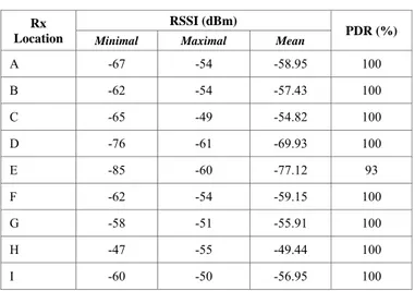
Table 1 presents obtained measurement results. For each Rx location, we give the minimal, maximal, and mean values of RSSI, as well as the PDR.
Measurement results of locations A, B, C, D, F, G, H and I show an excellent connectivity inside the motorhome with a PDR of 100 % and an average of RSSI above -70 dBm. The wireless node of the central control unit may have a reliable communication with all the ZigBee sensor/actuator nodes placed inside the motorhome. Closing the curtain (represented by a green dashed line in Figure 3) which separates the two compartments and blocking the line-of-sight between Tx and Rx at locations (A, B, C, D and F) has not affected the link quality. Moreover, the communication between Tx and Rx (location D) has not been blocked when closing the door of wardrobe, in spite of the attenuation of 10 dB with respect to other locations in the sleeping compartment. This remarkable link quality may be explained by the short distances separating Tx and Rx (the length of the motorhome is only 7 m) and the absence of severe obstacles that can totally block wireless communication (metallic walls for example).
However, location E (on the roof of the camper) does not show the same link quality. PDR decreased to 93% and the average of RSSI to -77 dBm. There is no direct visibility between Tx and Rx for this location. Radio signals are received by Rx due to reflections on walls and ceiling. It is worth mentioning here that all these measurements were performed when the motorhome was parked in a huge hangar. Therefore, reflections on the walls of the hangar guided radio signals between Tx and Rx. Although the mentioned results are not very bad, they may be worst if the motorhome was moving in an open area (outside reflections). In order to have an efficient connection between the central node and the external node, it will be recommended to place the node inside the motorhome and connect it by short cables to external sensors (temperature, humidity, etc.). In this case, successful data transmission will be more guaranteed and independent of the motorhome location. However, in this system, the security aspect has not been considered. It may be taken into account in future work.
TABLE I. OBTAINED RESULTS FROM ZIGBEE MEASUREMENTS
Rx Location
RSSI (dBm)
PDR (%)
Minimal Maximal Mean
A -67 -54 -58.95 100 B -62 -54 -57.43 100 C -65 -49 -54.82 100 D -76 -61 -69.93 100 E -85 -60 -77.12 93 F -62 -54 -59.15 100 G -58 -51 -55.91 100 H -47 -55 -49.44 100 I -60 -50 -56.95 100
V. PLCMEASUREMENTS
Several functionalities like video monitoring, multimedia exchange or Internet sharing may be added to the system. These functionalities do not need high level of security, but need a relatively high throughput which cannot be provided by CAN or ZigBee networks. We propose to study the feasibility of PLC inside the motorhome, on the DC power lines. This technology does not need new wires and is already used in indoor networks. Two types of measurements have been carried out in the same motorhome. The first one studies the transfer function on the electrical harness and the second one uses indoor PLC modems to determine the possible throughput in a motorhome.
A. Transfer Functions
In order to determine the best frequency band for PLCs as well as the effect of the battery and amenities in a motorhome, we started by measuring the transfer function of the electrical harness of a motorhome. Autostar has provided an electrical harness before its installation in a motorhome as well as a motorhome with installed harness. Using a Vector Network Analyzer (VNA), we have measured the S21 parameter for two different locations (AB and AC) on the harness in three different scenarios: a free harness (without equipment and battery connected), in the motorhome with only connected equipments (without battery) and finally with connected battery and equipments. The 12 V DC battery of the camper is totally independent from the engine one. The measurement point B is located in the living room and corresponds to the television location. Position C is located in the bed room. The performed measurements may simulate multimedia sharing between the two compartments of the motorhome. The measurement parameters are presented in Table 2.
Figure 4 shows the measurements positions in the motorhome. Figure 5 and Figure 6 present the obtained results in the three scenarios for paths AB and AC, respectively. One can observe a remarkable attenuation for frequencies less than 3 MHz may be noticed for the two scenarios. Secondly, the effect of connecting equipments start at frequencies higher than 50 MHz, however the effect of connecting a battery is clear for all frequencies (an average of 15 dB of attenuation). Finally, we can clearly conclude from these measurements that frequency band [3, 30 MHz] is the less affected by the battery and equipments and may be convenient for PLCs in a motorhome. More particularly, the bandwidth between 8 and 14 MHz has a minimum attenuation in this band.
TABLE II. S21MEASUREMENT PARAMETERS VNA Model Agilent FieldFox Handheld Analyzer N9918A Frrequency band [30 kHz – 100 MHz]
Resolution 4001 points (24,986 kHz)
IF bandwidth 30 kHz
Coupling Capacitive
Figure 4. Locations of DC-PLC transmitter and receiver in the motorhome.
Figure 5. Transfer function (S21) for path AB.
Figure 6. Transfer function (S21) for path AC.
B. Throughput Measurements
The study of PLC throughputs is realized using PLC Devolo 200Av modems [10] based on the HomePlug AV standard [11]. These modems are commonly used in indoor networks and cars [12] and high throughputs have been demonstrated. It is interesting to test them in a motorhome. As the power line network in-motorhome is different from that in a house, the modems have been modified to be used and plug on the DC power lines. The modifications affect mainly the coupling and the power supply.
The HomePlug AV standard is the second generation of PLC systems developed by the HomePlug Powerline Alliance. Now it is suitable for multimedia applications like HDTV or
VOIP. The PHY layer uses a windowed-OFDM modulation in the [2 – 28 MHz] frequency band over 972 subcarriers. The HPAV can use different modulation order from binary phase-shift keying (BPSK) up to 1024 quadrature amplitude modulation (QAM) for each sub-carrier according to the channel characteristics. To counteract the channel multipath effects and the inter-symbol interferences, the HPAV uses a guard interval (GI). Moreover, several GI (5.56 μs, to 47.12 μs) can be used depending on the channel and so the throughput can be improved. A frequency mask is used to avoid interferences mainly with amateur radio bands. This is the reason why the pulse-shaped OFDM symbols is different than the classic rectangular window. Thanks to this specific window, the out-of-band noise is reduced and the notches are deeper. The central coordinator uses the channel estimation in order to establish a specific QAM modulation for each OFDM sub-carrier. HPAV uses a two-level MAC framing scheme. Indeed, the MAC frames are divided into 512 bytes segments called PHY Block (PB). An uncorrectable Forward Error Correction (FEC) code is used and a header is added with the numbers of the PB.
In the measurement setup, we use a test bed with two PLC modems and two laptops running jperf tool, which is used for network testing by transmitting transmission control protocol (TCP) and user datagram protocol (UDP) streams. These modems have been plugged firstly to positions A and B, and then to positions A and C respectively to measure the throughput of the same scenarios studied in the previous section.
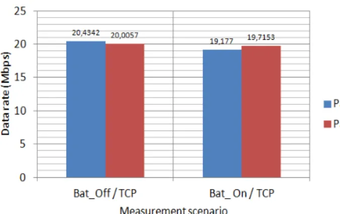
Figure 7 shows the obtained throughput for the two paths with disconnected and connected battery respectively. We can remark from these scenarios that obtained throughputs are quasi-similar for the two paths and are about 20 Mbps, which is higher than throughputs provided by other bus technologies (maximum 10 Mbps for FlexRay). However, we can notice a small decrease of about 1 Mbps for the two paths when the battery is connected. Similar results have been achieved with UDP and so not represented. These results show that HPAV modems can be used for PLCs in a motorhome for multi-media applications.
Figure 7. Obtained throughputs for paths AB and AC.
VI. CONCLUSION
We have presented in this paper centralized hybrid architecture for motorhome control mainly based on CAN bus, in addition to PLC and ZigBee technologies. Different simulations and measurements have been carried out to study the performance of these technologies in the motorhome.
Firstly, CAN bus simulations have been carried out using CANoe to evaluate the performance of the future network. Then, CAN nodes board and an embedded C code have been developed and tested successfully on the network in the motorhome.
Otherwise, ZigBee measurements have shown an excellent link quality between the central node and all locations inside the motorhome. Motorhome environment is not a difficult from a “radio wave propagation” view, as distances between nodes will be small and there is no severe obstacle that can totally block wireless communications. The security may be considered in future work.
Finally, PLC experimentations have shown the possibility of using PLC modems used in indoor applications in a motorhome. Possible data rates of about 20 Mbps in realistic scenarios can be provided by PLCs.
The obtained results confirm the possibility of using ubiquitous communication technologies to achieve a smart, convenient and comfortable motorhome. In future work, electromagnetic measurements will be performed in order to test the robustness of the network in real environment with the camper van in motion.
REFERENCES
[1] RVBusiness, “SSI: Motorhomes sales up 9.1% during October”, Available from http://www.rvbusiness.com/2014/12/ssi-motorhomes-sales-see-9-1-rise-in-october, [retrieved 12, 2014].
[2] F.Nouvel, W. Gouret, P. Maziero and G. EL Zein, " Automotive Network Architecture for ECUs Communications", in Automotive Informatics and Communicative Systems: Principles in Vehicular Networks and Data Exchange, IGI Global, pp 69-90, 2009.
[3] M. Ortiz, M. Diaz, Manuel, F. Bellido,E. Saez, Edmundo and F. Quiles, "Smart Home Automation Using Controller Area Network", International Symposium on Distributed Computing and Artificial Intelligence, pp 167-174, 2011.
[4] K. H. Johansson, M. Törngren and L. Nielsen, “Vehicle Applications of Controller Area Network,” in Handbook of Networked and Embedded Control Systems Control, 1st ed. Basel, Switzerland: Birkhäuser Basel,
sec. 6.1, pp 741-765, 2005.
[5] K. C. Lee and H. H. Lee, “Network-based fire-detection system via controller area network for smart home automation,” IEEE Trans. on Consumer Electronics, vol. 50, no. 4, pp. 1093-1100, 2004.
[6] K. H. The, W. L. Ng, C. K. Ng and N. K. Noordin, “Home Appliances Management System using Controller Area Network (CAN) Communications", APCC, 17th Asia-Pacific Conference on , pp.899-904, 2011.
[7] Website of ZigBee Alliance, ZigBee Alliance. [Online]. Available: http://www.zigbee.org.
[8] X. Lu; Y. Sun; and I. H. Kim, "Reliable power line communication A vehicle to smart home and smart energy," Consumer Electronics (ICCE), 2012 IEEE International Conference on, pp.86-87, 2012.
[9] Website of Vector Informatic GmbH. Vector Informatic GmbH. Available at http://www.vector.com [retrieved 6, 2015].
[11] Official website of the HomePlug Powerline Alliance (HPA). HomePlug Powerline Alliance. Available at http://www.homeplug.org [retrieved 08, 2015].
[12] P. Tanguy, F. Nouvel, P. Maziearo, “Power Line Communication standards for in-vehicule networks,” 9th ITST2009, Intenational
Conference on Intelligent Transport Systems Telecommunications, pp.533-537, 2009.
![TABLE II. S21 M EASUREMENT P ARAMETERS VNA Model Agilent FieldFox Handheld Analyzer N9918A Frrequency band [30 kHz – 100 MHz]](https://thumb-eu.123doks.com/thumbv2/123doknet/11587520.298482/7.892.468.830.286.493/table-easurement-arameters-agilent-fieldfox-handheld-analyzer-frrequency.webp)