NONLINEAR BEHAVIOUR OF COUPLED SHEAR
WALLS STRENGTHENED WITH EXTERNALLY
BONDED CARBON FIBRE REINFORCED POLYMER
COMPOSITE UNDER SEISMIC LOADINGS
by
Sara HONARPARAST
MANUSCRIPT-BASED THESIS PRESENTED TO ÉCOLE DE
TECHNOLOGIE SUPÉRIEURE IN PARTIAL FULFILLMENT FOR THE
DEGREE OF DOCTOR OF PHILOSOPHY
Ph.D.
MONTREAL, NOVEMBER 21, 2018
ÉCOLE DE TECHNOLOGIE SUPÉRIEURE UNIVERSITÉ DU QUÉBEC
© Copyright reserved
It is forbidden to reproduce, save or share the content of this document either in whole or in parts. The reader who wishes to print or save this document on any media must first get the permission of the author.
BOARD OF EXAMINERS
THIS THESIS HAS BEEN EVALUATED BY THE FOLLOWING BOARD OF EXAMINERS
Mr. Omar Chaallal, Thesis Supervisor
Department of Construction Engineering at École de technologie supérieure
Mr. Anh Dung Ngô, President of the Board of Examiners
Department of Mechanical Engineering at École de technologie supérieure
Mr. Amar Khaled, Member of the jury
Department of Construction Engineering at École de technologie supérieure
Mr. Radhouane Masmoudi, External Evaluator
Department of Civil Engineering, Université de Sherbrooke
THIS THESIS WAS PRESENTED AND DEFENDED
IN THE PRESENCE OF A BOARD OF EXAMINERS AND PUBLIC ON 12 NOVEMBER, 2018
ACKNOWLEDGMENTS
Firstly, I would like to express my deepest appreciation to my supervisor Prof. Omar Chaallal for his continuous support during my Ph.D study, for his patience, motivation, and immense knowledge. His guidance helped me during my research period as well as writing of this thesis. I am extremely grateful for his valuable support and friendship at academic and personal levels.
I also would like to offer my special thanks to the members of my Ph.D. committee who evaluated my thesis and provided valuable feedback.
The efficient collaboration of the technicians, Mr. John Lescelleur, Mr. Andres Barco, and the application engineer, Mr. Richard Prowt, in conducting the experimental tests at ÉTS structural laboratory is gratefully acknowledged.
Furthermore, I would like to thank Dr. Georges El-Saikaly for his help in performing the experimental tests.
I am also grateful to my friends in Canada for their support and friendship.
Last but not the least, my sincere thanks also go to my family, especially my beloved parents for their endless love and support in all stages of my life.
Comportement non linéaire sous charges sismiques de murs de refend couplés renforcés à l'aide de composite en polymeres renforcés de fibres de carbone collés en surface
Sara HONARPARAST RÉSUMÉ
L’efficacité des murs de refend couplés (MRC) en béton armé (BA), comme système pour résister aux forces latérales dues aux vents et aux séismes, est bien établie. Les MRC sont généralement utilisés pour les bâtiments multi-étages de moyenne à grande hauteur. Ils résistent aux forces latérales grâce à la conjonction de la résistance au cisaillement et à la flexion de leurs segments de mur d’une part, et d’autre part à l'action des forces de cisaillement de leurs poutres de couplage. En effet, les forces de cisaillement générées par les poutres de couplage sont transférées aux murs sous forme de forces axiales de compression-traction générant ainsi un moment de flexion résistant au moment de renversement. Un MRC adéquatement conçu et détaillé devrait garantir que: (i) les poutres de couplage atteignent leur limite élastique (plastification) avant les murs; (ii) les poutres de couplage ne présentent pas de dégradation de résistance ou de rigidité sévère sous charges cycliques; et (iii) les poutres de couplage sont les éléments principaux de dissipation d'énergie en fournissant des boucles d'hystérésis stables et sans pincements. Cependant, concevoir et détailler des poutres de couplage offrant toutes ces propriétés importantes n'étaient pas possibles avant les années 1970. Aussi, les MRC construits avant 1970 risquent d’être sévèrement endommagés dans le cas d’un séisme modéré à sévère. De nombreuses techniques conventionnelles ont été utilisées avec plus ou moins de succès pour mettre à niveau et renforcer les structures déficientes et améliorer ainsi leur performance sismique. Au cours des dernières années, l'utilisation de matériaux composites à base de polymères renforcés de fibres (PRF) collés en surface s'est révélée être une méthode novatrice, efficace et économiquement viable pour la mise en état des structures en BA existantes. Cette thèse présente les résultats d'une étude expérimentale et des simulations numériques sur le comportement sismique, l'évaluation et la mise à niveau de MRC en BA existants conçus selon les codes et les normes d’avant les années 1970.
Dans la partie expérimentale de cette étude, une méthode novatrice de renforcement externe utilisant un tissu de PRF de carbone (PRFC) a été proposée pour améliorer les performances sismiques des poutres de couplage en BA déficientes. À cette fin, deux échantillons de MRC avec une poutre de couplage en béton armé conventionnelle, représentatifs des MRC conçus selon les codes canadiens d’avant les années 1970, ont été considérés comme suit: Le premier a été utilisé comme spécimen de référence alors que le second a été renforcé avec du composite en PRFC collé en surface. Les deux spécimens ont été testés sous charge cyclique inversée pour évaluer l'efficacité de la méthode de renforcement proposée.
De plus, un autre spécimen a été conçu en conformité à la norme de conception canadienne moderne en vigueur, c’est à dire avec poutre de couplage avec armatures diagonales. Ce spécimen a été soumis à un chargement cyclique jusqu'à un certain endommagement simulant un séisme. Par la suite, le spécimen endommagé a été réparé à l'aide de tissus en
PRFC collés en surface et de nouveau testé sous une charge cyclique inversée afin d’évaluer l'efficacité de la technique de réparation proposée.
Les résultats expérimentaux ont révélé l’efficacité du système de renforcement en PRFC quant à l’amélioration de la résistance, la ductilité et la capacité de dissipation d'énergie de la poutre de couplage conçue selon la norme d’avant 1970 avec armature conventionnelle. Par ailleurs, ils ont également montré que la méthode de réparation proposée sur la poutre de couplage avec armature diagonale mais endommagée par un séisme, permet de recouvrer les propriétés initiales avant endommagement et notamment la résistance, la rigidité, la ductilité et la capacité de dissipation d'énergie.
Les simulations numériques de cette étude ont porté sur l’analyse non linéaire temporelle d’un prototype de bâtiment de 20 étages situé au Canada, contreventé à l’aide de MRC. Quatre modèles de MRC dont deux modèles identiques sont conçus selon le Code national du bâtiment du Canada (CNBC) d’avant les années 1970 et les deux autres modèles sont conçus conformément au nouveau code de conception (CNBC 2015) et à la nouvelle norme (CSA A23.3-14) pour Montréal et Vancouver, représentatives de l'est et de l'ouest du Canada, respectivement. Des analyses dynamiques non linéaires utilisant le logiciel RUAUMOKO ont été réalisées sous accélérations sismiques étalonnées afin d'étudier le comportement structural des MRC, l'efficacité des normes modernes en vigueur et les déficiences des MRC conçus selon les normes d’avant 1970. Une méthode de renforcement à l’aide de composites en PRFC collés en surface a été proposée pour les structures de MRC déficientes, conformément au nouveau code de conception sismique. Les effets de cette méthode de renforcement sur l'amélioration du comportement sismique de ces MRC ont été étudiés par des analyses non linéaires temporelles.
Les résultats de cette étude numérique ont révélé l’efficacité de la technique de renforcement à l’aide de PRFC puisqu’elle a permis d’améliorer la séquence de plastification, c’est-à-dire dans les poutres avant les murs, de réduire le déplacement latéral et inter-étage, et enfin de réduire la rotation des poutres de couplage et la demande en ductilité. L’étude a également révélé que, contrairement à l'ancien CNBC d’avant 1970, les exigences prescrites dans les normes CSA A23.3-14 et CNBC 2015 pour la conception en capacité des MRC ductiles sont satisfaisantes et se rapprochent des demandes sismiques.
Mots clés: murs de refend couplés, poutre de couplage, renforcement, composite en PRFC, collé en surface, performance sismique, essai de chargement cyclique, analyse sismique temporelle non linéaire
Nonlinear Behaviour of Coupled Shear Walls Strengthened with Externally Bonded Carbon Fibre Reinforced Polymer Composite under Seismic Loadings
Sara HONARPARAST ABSTRACT
Reinforced concrete (RC) coupled shear walls (CSWs) with adequate strength and stiffness can be an effective system to resist lateral forces such as wind and earthquakes. CSWs are generally used for medium-high rise buildings. They resist lateral forces not only through the shear and moment resistance of their wall segments, but also through the shear action of their coupling beams (CBs). In CSWs, the shear forces are transferred through the CBs, and the overturning moment is partially resisted by an axial compression-tension that is coupled across the walls. A properly designed CSW should ensure that: (i) plastic hinging occurs in the CBs before it does in the walls; (ii) the CBs do not show major strength or stiffness degradations with load reversal; and (iii) the CBs should function as the primary energy-dissipation elements by providing stable energy-absorbing hysteresis loops without pinching. However, designing and detailing CBs with all these important features were not possible before the 1970s. Therefore, the old existing CSWs are potentially at risk of suffering severe damage under moderate to severe earthquakes. Many conventional techniques have been used with some success to retrofit and strengthen deficient structures and thereby improve their seismic performance. In the last few years, the use of externally bonded (EB) fiber reinforced polymer (FRP) composites has proven to be an innovative, reliable and a cost effective retrofit method for RC structures. This study presents results of an experimental and analytical investigation on the seismic behavior, evaluation, and retrofit of reinforced concrete CSWs designed according to codes and Standards before the 1970s.
In the experimental part of this study, a new retrofit method using carbon FRP (CFRP) sheets was proposed to enhance the seismic performance of deficient reinforced concrete CBs. To that end, two coupled shear wall specimens with conventionally reinforced CB, representative of CSWs designed according to Canadian codes prior to the 1970s were considered as follows: One as a control specimen and the other strengthened using EB-CFRP. Both specimens were tested under reversed cyclic loading to assess the efficiency of the proposed retrofit method.
In addition, one more specimen was designed according to modern Canadian design code and Standard with a diagonally reinforced CB. This specimen was submitted to cyclic loading up to failure simulating a seismic loading. Thereafter, the damaged specimen was repaired using EB-CFRP sheets and retested under reversed cyclic loading to investigate the effectiveness of the proposed repair technique.
Experimental results revealed the ability of the CFRP retrofitting system to increase load carrying, ductility and energy dissipation capacity in deficient CB specimen designed according to old codes. In addition, the proposed repair method is also capable of recovering
the initial strength, stiffness, ductility and energy dissipation capacity in severely damaged CB specimen with diagonal reinforcement.
The numerical part of this research study dealt with nonlinear time history analysis of a prototype 20-story coupled shear wall structure located in Canada. Four CSW prototype structures including two identical CSWs designed according to old National Building Code of Canada (NBCC) before 1970s, and two CSWs designed according to new design code (NBCC 2015) and Standard (CSA A23.3-14) located in Montreal and Vancouver as representative of East and West of Canada, respectively. Nonlinear dynamic analyses using RUAUMOKO were conducted under scaled earthquake accelerations to investigate the CSW structural behavior, adequacy of the design, and the deficiencies of old designed CSWs. An EB-CFRP retrofit method was proposed for deficient CSW structures to be in conformity with the new seismic design code. The beneficial effects of this retrofit method on seismic behavior of such CSWs was investigated through nonlinear time history analyses.
The results of this analytical study revealed that the CFRP retrofitting technique performed very well since it resulted in improved sequence of yielding in CBs and walls, and reduced story displacement, inter-story drift, CBs rotation, and ductility demand. It was also found that unlike old NBCC, the requirements prescribed by CSA A23.3-14 and NBCC 2015 for the capacity design of ductile coupled walls are acceptable in approximating seismic demands.
Keywords: coupled shear wall, coupling beam, strengthening, CFRP composite, externally bonded, seismic performance, cyclic loading test, non-linear time history analysis
TABLE OF CONTENTS Page INTRODUCTION ...1 0.1 General………...………...1 0.2 Problem statement………..2 0.3 Research objectives………4 0.4 Research methodology………...4 0.5 Research significance……….6 0.6 Organization of dissertation………...7
CHAPTER 1 BACKGROUND AND LITERATURE REVIEW ...9
1.1 General definition of coupled shear walls ...9
1.2 Experimental studies on conventionally and diagonally reinforced CBs ...10
1.3 Alternative designs of CBs ...14
1.3.1 Steel CBs and steel-concrete composite CBs ... 14
1.3.2 Steel-fiber-reinforced concrete CB ... 19
1.4 Retrofitting methods of RC CSWs ...20
1.4.1 Attaching steel plates to RC CBs ... 20
1.4.2 Adding new RC CBs ... 22
1.4.3 Strengthening of CBs with fibre reinforced polymer ... 22
1.5 Non-linear analysis of CSWs ...23
1.6 Previous studies on analysis of CSWs ...24
CHAPTER 2 SEISMIC UPGRADING OF RC COUPLED SHEAR WALLS : STATE OF THE ART AND RESEARCH NEEDS ...29
2.1 Abstract ...29
2.2 Introduction ...29
2.3 Importance of CBs in coupled shear walls ...31
2.4 Deficiencies of existing CSWs ...33
2.4.1 Evolution of seismic loading ... 33
2.4.2 Design evolution of CSWs... 36
2.5 Diagonal reinforcement concept for CBs ...37
2.6 Failure modes of coupled shear walls ...39
2.6.1 Flexural failure mode ... 40
2.6.2 Shear failure mode ... 40
2.6.3 Rigid action ... 41
2.7 Review of retrofit and upgrading methods for CSWs ...41
2.7.1 Application of steel plates to one side of shear-deficient reinforced CBs ... 42
2.7.2 Upgrading the degree of coupling of coupled shear walls ... 43
2.7.3 Attaching external steel plates to the side faces of CBs ... 44
2.7.4 Application of fiber-reinforced polymer sheet ... 45
2.8.1 Steel CBs with and without stiffeners ... 47
2.8.2 Concrete-filled steel-tube CBs ... 47
2.8.3 Steel CBs encased in reinforced concrete members ... 48
2.8.4 Embedded steel-composite CB with shear studs ... 49
2.9 Retrofit of beam-wall joints ...49
2.10 Advantages and disadvantages of retrofit methods and perspectives for FRP composites...51
2.11 Required research ...53
2.12 Conclusions ...54
CHAPTER 3 EXPERIMENTAL SEISMIC PERFORMANCE EVALUATION OF CBs: COMPARISON OF OLD WITH MODERN CODES ...55
3.1 Abstract ...55 3.2 Introduction ...55 3.3 Experimental program ...59 3.3.1 Test specimens ... 60 3.3.2 Material properties ... 60 3.3.3 Instrumentation ... 62
3.3.4 Test setup and loading procedure ... 62
3.4 Test results and discussion ...64
3.4.1 Failure modes ... 64
3.4.2 Load-Displacement Hysteretic Curve ... 67
3.4.3 Displacement ductility ... 68
3.4.4 Energy dissipation ... 70
3.4.5 Strength and stiffness degradation ... 71
3.5 Conclusions ...72
3.6 Acknowledgement ...74
CHAPTER 4 EXTERNALLY BONDED CFRP COMPOSITES FOR SEISMIC RETROFIT OF RC CBS DESIGNED ACCORDING TO OLD CODES ...75
4.1 Abstract ...75 4.2 Introduction ...76 4.3 Experimental program ...80 4.3.1 Test specimens ... 81 4.3.2 Material properties ... 82 4.3.3 Strengthening procedures ... 82 4.3.4 Instrumentation ... 84
4.3.5 Test setup and loading program ... 86
4.4 Test results and discussion ...87
4.4.1 Failure modes ... 87
4.4.2 Load-Displacement Hysteretic Curve ... 89
4.4.3 Ductility ... 89
4.4.4 Energy dissipation ... 91
4.4.5 Strength and stiffness degradation ... 92
4.4.7 Contributions of the components to the shear resistance ... 94
4.5 CONCLUSIONS...96
CHAPTER 5 SEISMIC RETROFIT OF PRE-DAMAGED DIAGONALLY RC CBS USING EXTERNALLY BONDED CFRP COMPOSITES ...99
5.1 Abstract ...99
5.2 Introduction ...99
5.3 Experimental program ...102
5.3.1 Test specimen and instrumentation ... 103
5.3.2 Material properties ... 104
5.3.3 Repairing procedures ... 106
5.3.4 Test setup and loading program ... 107
5.4 Test results and discussions ...109
5.4.1 Failure modes ... 109
5.4.2 Load-Displacement Hysteretic Curve ... 111
5.4.3 Ductility ... 112
5.4.4 Energy dissipation ... 114
5.4.5 Strength and stiffness degradation ... 114
5.4.6 Strain in EB-CFRP strips ... 116
5.4.7 Contributions of the components to the shear resistance ... 117
5.5 CONCLUSIONS...119
CHAPTER 6 NON-LINEAR TIME HISTORY ANALYSIS AND COMPARISON OF COUPLED SHEAR WALLS DESIGNED ACCORDING TO OLD AND MODERN CODES AND SEISMIC RETROFIT WITH EXTERNALLY BONDED CFRP COMPOSITES FOR EASTERN CANADA ...121
6.1 Abstract ...121
6.2 Introduction ...122
6.3 Canadian seismic design provisions ...126
6.4 CSA standard A23.3-14 provisions for the design of CSWs ...129
6.5 Description of studied building ...130
6.6 Retrofit of deficient CSW1941 using EB-CFRP composite ...133
6.7 Non-linear time history analysis of CSWs ...135
6.7.1 Inelastic structural models ... 135
6.7.2 Selecting and scaling of earthquake ground motion histories ... 138
6.8 Inelastic seismic analysis results ...140
6.8.1 Displacement and inter-story drift ... 140
6.8.2 Story shear of the wall piers ... 143
6.8.3 Flexural moment of wall piers ... 143
6.8.4 Beam rotations ... 145
6.8.5 Sequence of plastic hinge formation ... 146
6.8.6 Wall curvature ... 147
CHAPTER 7 NON-LINEAR TIME HISTORY ANALYSIS OF COUPLED SHEAR WALLS: COMPARISON OF OLD DESIGN, MODERN DESIGN AND RETROFITTED WITH EXTERNALLY BONDED CFRP
COMPOSITES FOR WESTERN CANADA ...151
7.1 Abstract ...151
7.2 Introduction ...152
7.3 Canadian seismic design provisions ...155
7.4 CSA standard A23.3-14 provisions for the design of CSWs ...158
7.5 Description of studied building ...160
7.6 Retrofit of deficient CSW1941 using EB-CFRP composite ...163
7.7 Non-linear time history analysis of CSWs ...165
7.7.1 Inelastic structural models ... 165
7.7.2 Selecting and scaling of earthquake ground motion histories ... 168
7.8 Inelastic seismic analysis results ...170
7.8.1 Displacement and inter-story drift ... 170
7.8.2 Story shear of the wall piers ... 172
7.8.3 Beam rotations ... 173
7.8.4 Flexural moment of wall piers ... 174
7.8.5 Sequence of plastic hinge formation ... 175
7.8.6 Wall curvature ... 176
7.9 Conclusions ...178
CONCLUSION ...181
RECOMMENDATIONS ...185
LIST OF TABLES
Page
Table 2.1 Consideration of design provisions for single shear walls and coupled
shear walls in ACI 318 and CSA standard A23.3 ...32
Table 2.2 Evolution of seismic design forces in the NBCC from 1941 to 1970 ...34
Table 2.3 Evolution of seismic design forces in the NBCC from 1975 to 1995 ...35
Table 2.4 Evolution of seismic design forces in the NBCC from 2005 to 2010 ...36
Table 2.5 Different retrofit methods and alternative design of CBs ...42
Table 2.6 Advantages and disadvantages of retrofit methods for CBs ...52
Table 2.7 Advantages and disadvantages of alternative designs for CBs ...53
Table 3.1 Seismic design force: NBCC 1941 versus NBCC 2010……..….……...53
Table 3.2 Properties of steel reinforcing bars………...…….…..…………...60
Table 3.3 Ductility and deformability of the test specimens…….…..…………...69
Table 3.4 Comparison of results obtained from CB1 and CB2 experimental tests………...74
Table 4.1 Properties of materials used in strengthening procedure ...82
Table 4.2 Ductility and deformability of test specimens ...90
Table 5.1 Properties of steel reinforcing bars ...105
Table 5.2 Properties of materials used in repairing and rehabilitating procedure ...105
Table 5.3 Ductility and deformability of the test specimens ...113
Table 6.1 Higher mode factor Mv according to NBCC-2015 ...128
Table 6.2 Seismic force modification factors, Rd and Ro according to NBCC-2015 ...128
Table 6.3 Properties of CFRP sheet (SikaWrap 1400 with epoxy Sikadur 300) ...134
Table 6.5 Properties of input earthquake accelerations ...140
Table 7.1 Higher mode factor Mv according to NBCC 2015 ...157
Table 7.2 Seismic force modification factors, Rd and Ro according to NBCC 2015 ...157
Table 7.3 Properties of CFRP sheet (SikaWrap 1400 with epoxy Sikadur 300) ...163
Table 7.4 Hysteresis behavior and defined parameters in RUAUMOKO ...167
LIST OF FIGURES
Page
Figure 1.1 Forces in CSWs subjected to lateral load ...10 Figure 2.1 Shear walls under lateral load: a) single shear wall, b) coupled shear
walls ...31 Figure 2.2 Plastic hinging sequence in CSW: (a) Not desirable; (b) Desirable ...33 Figure 2.3 CBs: (a) conventionally reinforced CB, (b) hysteresis behavior of
conventional CB, (c) diagonally reinforced CB, (d) hysteresis behavior of diagonal CB ...38 Figure 2.4 Distribution of forces in diagonal reinforcements (adapted from
Harries, 1995) ...39 Figure 2.5 Modes of failure of CBs: a) flexural failure, b) shear failure, c) rigid
action (adapted from Subedi, 1991) ...41 Figure 2.6 Methods of attaching steel plate to CBs: a) epoxied steel plate,
b) epoxied and bolted steel plate, c) steel plate extended to walls
(adapted from Harries, 1995) ...43 Figure 2.7 Configuration of specimens (adapted from Su & Zhu, 2005) ...45 Figure 2.8 Alternative designs of CBs: a) steel coupling I-beam with stiffeners;
b) steel CB with concrete encasement; c) concrete-filled steel-tube CB; d) steel composite CB with shear studs ...50 Figure 3.1 Coupled wall system and behavior: (a) coupled wall system, (b) wall
section in actual structure, (c) simulation of CSW in experimental test ....59 Figure 3.2 Geometry, reinforcement details, and instrumentation of specimens: (a)
conventional CB (CB1), (b) diagonal CB (CB2) (dimensions in mm) ...61 Figure 3.3 Experimental set-up ...63 Figure 3.4 Loading sequence ...63 Figure 3.5 Estimation of the yield point of the CB specimens through static
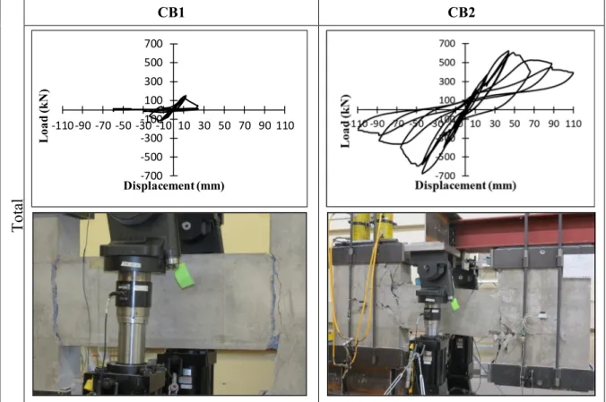
loading...63 Figure 3.6 Specimens’ behavior in some selected cyces ...65
Figure 3.7 Hysteretic behavior of specimens ...68
Figure 3.8 Ductility factor: (a) Method of computing ductility factor, (b) Ductility of specimens during each loading cycle ...69
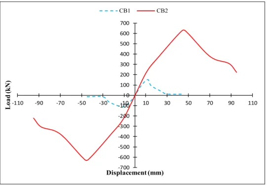
Figure 3.9 Envelope of hysteretic loops of specimen CB1, CB2 ...70
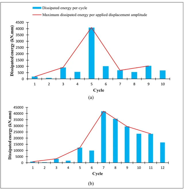
Figure 3.10 Cumulative dissipated energy per cycle for specimens (a) CB1, (b) CB2...71
Figure 3.11 Strength and stiffness degradation of specimens CB1, CB2: a) Strength degradation, b) Stiffness degradation ...72
Figure 4.1 Response of CSW to lateral loading: (a) actual structure, (b) experimental test setup ...81
Figure 4.2 Geometry and reinforcement details of conventionally reinforced CB ...81
Figure 4.3 Strengthening procedure for the CB specimen: (1) Impregnation of fibers with Sikadur 300, (2) Coating the concrete surface with Sikadur 330, (3) Bonding the first strip of CFRP onto one diagonal, (4) Bonding the second strip of CFRP to another diagonal ...85
Figure 4.4 Strain gauges installed onto steel reinforcements and CFRP strips: a) CB.CONV, b) CB.CONV-R ...85
Figure 4.5 Experimental setup...86
Figure 4.6 Loading sequence ...87
Figure 4.7 Crack pattern of specimens at failure: (a) CB.CONV, (b) CB.CONV-R ...88
Figure 4.8 Hysteretic behavior of specimens ...89
Figure 4.9 Envelopes of hysteretic loops of specimens CB.CONV and CB.CONV-R ...91
Figure 4.10 Energy dissipation of specimens CB.CONV and CB.CONV-R ...91
Figure 4.11 Strength degradation of specimens ...92
Figure 4.12 Stiffness degradation of specimens ...93
Figure 4.13 Strain of CFRP along the CSW ...94
Figure 4.14 Component shear contributions of specimens: (a) CB.CONV (b) CB.CONV-R ...96
Figure 5.1 Response of CSW to lateral loading: (a) actual structure,
(b) experimental test setup ...102
Figure 5.2 Geometry, reinforcement details, CFRP configuration, and instrumentation : (a) original coupling specimen, (b) rehabilitated specimen using CFRP strips, (dimension in mm) ...104
Figure 5.3 Repair and rehabilitation procedures of CB specimen: (a) repair, (b) rehabilitation ...108
Figure 5.4 Experimental setup...109
Figure 5.5 Crack pattern of specimens at failure: (a) CB.DIAG, (b) CB.DIAG-R... 110
Figure 5.6 Hysteretic behavior of specimens ...111
Figure 5.7 Envelopes of hysteretic loops of specimens CB.DIAG and CB.DIAG-R ...112
Figure 5.8 Ductility factor: (a) Method of computing ductility factor, (b) Ductility of specimens during each loading cycle ...113
Figure 5.9 (a) Comparison of energy dissipation capacity of specimens, (b) dissipated energy per cycle in CB.DIAG, (c) dissipated energy per cycle CB.DIAG-R ...115
Figure 5.10 Degradation of specimens CB.CONV and CB.CONV-R: a) strength degradation, b) stiffness degradation ...116
Figure 5.11 Strains in EB-CFRP along the CSW ...117
Figure 5.12 Component shear contributions of specimen CB.DIAG-R ...118
Figure 6.1 Elevation and plan view of studied building ...132
Figure 6.2 Design summary of CSW1941: (a) Reinforcement details of conventionally reinforced CBs, (b) Reinforcement details of a wall ...132
Figure 6.3 Design summary of CSW2015: (a) Reinforcement details of conventionally reinforced CBs, (b) Reinforcement details of one wall ...133
Figure 6.4 Design summary of CFRP retrofitted CSW: (a) Retrofitted CBs, (b) Retrofitted wall ...135
Figure 6.6 a) Determination of target spectrum, period range TR and scenario- specific period ranges TRS1 and TRS2; b) Acceleration spectra of the selected and scaled individual ground motion time histories; c) Mean acceleration spectra for scenarios 1 and 2; d) Difference between the mean Sg(T) of the scaled records and ST(T) within each scenario-
specific period range ...141 Figure 6.7 (a) Mean of story displacement under all earthquake inputs; (b) Inter-
story drift response envelopes ...142 Figure 6.8 Comparison of walls shear force ...144 Figure 6.9 Comparison of walls moment at each story level ...145 Figure 6.10 CBs rotation in CSW1941, CSW2015, and CFRP retrofitted
CSW1941-R ...146 Figure 6.11 Sequence of plastic hinge formation in CBs and at the base of the
walls ...147 Figure 6.12 Wall curvature envelopes for CSW1941, CSW2015, and
CSW1941-R ...148 Figure 7.1 Elevation and plan view of studied building ...161 Figure 7.2 Design summary of CSW1941: (a) Reinforcement details of
conventionally reinforced CBs, (b) Reinforcement details of a wall ...162 Figure 7.3 Design summary of CSW2015: (a) Reinforcement details of
conventionally reinforced CBs, (b) Reinforcement details of one wall ...162 Figure 7.4 Design summary of CFRP retrofitted CSW: (a) Retrofitted CBs, (b)
Retrofitted wall ...164 Figure 7.5 Types of elements in RUAUMOKO: (a) CBs model, (b) walls model ...165 Figure 7.6 a) Determination of target spectrum, period range TR and TRS1 and TRS2;
b) Acceleration spectra of the selected and scaled individual ground motion time histories; c) Mean acceleration spectra for scenarios 1 and 2; d) Difference between the mean Sg(T) of the scaled records and
ST(T) within each scenario-specific period range ...169 Figure 7.7 (a) Mean of story displacement under all earthquake inputs; (b) Inter-
story drift response envelopes ...171 Figure 7.8 Comparison of walls shear force ...173
Figure 7.9 CBs rotation in CSW1941, CSW2015, and CFRP retrofitted
CSW1941-R ...174 Figure 7.10 Comparison of walls moment at each story level ...175 Figure 7.11 Sequence of plastic hinge formation in CBs and at the base of the
walls ...176 Figure 7.12 Wall curvature envelopes for CSW1941, CSW2015, and
LIST OF ABREVIATIONS ACI American Concrete Institute
ASCE American Society of Civil Engineers ASTM American Society for Testing and Materials
CB Coupling Beam
CB.CONV Conventionally reinforced Coupling Beam CB.DIAG Diagonally reinforced Coupling Beam CFRP Carbon Fiber Reinforced Polymer CFRT Concrete-Filled Rectangular Tube CSA Canadian Standard Association CSW Coupled Shear Wall
DC Degree of Coupling
EB Externally Bonded
FRP Fiber Reinforced Polymer HCW Hybrid Coupled Wall
LVDT Linear Variable-Displacement Transducers NBCC National Building Code of Canada
PRC Plate-reinforced concrete Composite RC Reinforced Concrete
SFRC Steel-Fibre Reinforced Concrete SFRS Seismic Force Resisting System
LIST OF SYMBOLS
AI Axial rigidity
Asd Area of steel bars in one diagonal group
Av Area of the steel stirrups
C Type of construction factor
Ci Horizontal force factor
d Beam depth
DL Dead load
DSL Design snow load
dv Effective shear depth of the beam
EFRP Modulus of elasticity of the FRP sheets
EI Flexural rigidity
Es modulus of elasticity of the steel reinforcing bars
F Foundation factor
fc΄ Compressive strength of concrete
fu Ultimate tensile strength of steel reinforcing bars fy Yield strength of steel reinforcements
h Story height
hw Height of the wall
I Importance factor
Kα A measure of the relative stiffness of the coupling beams and walls
lcg Horizontal distance between the centroids of walls in CSWs
LL Live load
lu Clear span of coupling beam
lw Wall depth
M External moment applied to the structure
M1 Moment resisted by wall 1
M2 Moment resisted by wall 2
Mv Factor to account for the effect of higher modes
N Axial force
Ni Axial force related to the retrofitted CBs
P Axial force resulting from coupling action
Rd Ductility-related factor
Ro Overstrength-related factor
s Distance between the steel stirrups
S Structural flexibility factor
S(Ta) Design-spectral-response acceleration at the fundamental period
SL Snow load
Ta Fundamental period of vibration
tFRP Thickness of FRP sheets
V Shear Strength
Vc Shear resistance of concrete
VFRP Shear resistance FRP composites
Vn Nominal shear strength
Vs Shear resistance of transverse steel reinforcement
Vy Yield shear force
W Weight of the building
wFRP Width of the FRP strip
x Rigid portion
y Lateral deflection
z Height above the base of the structure
∆p Displacement at peak load
∆u Ultimate displacement
∆y Yield displacement
α Angle of diagonal bars and horizontal axis in coupling beam
β Angle of FRP strips and horizontal axis εFRPe Effective strain of the FRP sheets εs Steel strain
θu Ultimate rotation angle
θy Yield rotation
μd Displacement ductility
ν(x) Shear force intensity
φc Resistance factor for concrete
φFRP Resistance factor for FRP φs Resistance factor for steel
INTRODUCTION
0.1 General
A large number of reinforced concrete (RC) structures were designed and constructed before the development of modern building codes. The design of many of these old structures were dominated by gravity load effects, resulting in construction details that are now recognized to be associated with non-ductile failure modes under seismic loading. Numerous old existing buildings contain reinforced concrete coupled shear walls (CSWs) as lateral load resisting systems. The behavior of CSWs built prior to the 1970s, is assessed to be potentially critical in the event of an earthquake. This is due to shortcomings of their coupling beams (CBs) and their wall segments related to lack of little or no transverse reinforcement in the CBs and near the wall ends, insufficient lap splices, poor anchorage of the transverse and longitudinal reinforcement, lack of flexural reinforcement, and poor construction joints under seismic loadings. Such deficiencies would lead to diagonal cracks in the CBs, yielding of the shear reinforcement before failure, formation of deep flexural cracks at the beam–wall joints, and sliding movement along the cracks at the beam–wall joints followed by brittle shear failure. Therefore, appropriate measures such as replacement of the structure or seismic retrofit of lateral resisting system should be taken to address these deficiencies.
In the past, several methods were used for strengthening or retrofitting RC structural buildings. Increasing the gross section through adding new structural material to an already existing structural element, posttensioning, replacing of some structural elements or changing the structural system, attaching steel plates to a concrete surface are some of the conventional techniques used in the past. Although these methods can be successful in some cases, they are not always cost-effective in enhancing the seismic performance and are often not sustainable.
During the last decades, Fibre-Reinforced Polymers (FRP) have received much attention for a variety of applications related to strengthening of defective structures. The outstanding mechanical properties of FRP combined with low weight, corrosion resistance and easy application make the FRP composites a real and viable solution to retrofit deficient RC structures. In spite of using FRP composites in different structural elements such as beams, columns, bridges, and slabs, more research is needed to extend the application to retrofit deficient RC CSWs.
This has been the main impetus to carry out the present research project, to investigate experimentally and numerically the effectiveness of EB- FRP composites in upgrading the seismic properties and response of CBs pertaining to old designed CSWs.
0.2 Problem statement
Many old existing RC buildings in developed countries and cities need to be strengthened due to the introduction of new seismic design requirements in modern codes and standards, rapid deterioration of reinforced concrete and poor original concrete quality. It is often more economical to retrofit deficient structural components than to replace the entire buildings. RC CSWs are widely used as a lateral load resisting system in medium to high-rise buildings to resist seismic loading. In CSWs, the individual wall piers are coupled together by CBs to increase the lateral strength and the stiffness of the buildings. The overturning moments are thereby resisted by an axial compression-tension couple across the wall system rather than by solely the individual flexural action of the walls. CBs in CSWs are an essential structural component since they transfer shear forces from one wall to another. Therefore, the beams must retain much of their ability to transfer load and to reduce the bending moment at the base of the CSWs. Otherwise, the small amount of shear force is transferred between the shear walls and due to the decrease of CBs’ load capacity, the wall piers act as two independent cantilevers.
From the viewpoint of earthquake resistance, the use of ductile structural components for dissipating energy to delay or prevent yielding of critical vertical elements is an important design strategy. Therefore, to achieve the optimum performance of CSWs in dissipating earthquake energy, plastic hinge formation in most of the CBs should occur prior to plastic hinging at the base of each wall. This means that the CBs must yield first and walls are the last to yield to maintain gravity load resistance of the structure and allow large deformation before collapse.
In past decades, the design of many concrete buildings in Canada did not take into account earthquake actions. Following the evolution of design codes, many existing CBs were found to be deficient in shear capacity. The past earthquake records caused brittle shear failure in many deep RC CBs accompanied with severe damage (Mitchell et al., 1995). This resulted in significant decrease in the structural safety of the entire building. Due to structural deficiencies, many of the existing CSWs are in need of strengthening and retrofit. As will be presented in the next chapter, in order to enhance the seismic behavior of CSWs, alternative design methods such as diagonally reinforced CBs, steel CBs, rectangular steel tube CBs with concrete infill and embedded steel plate CBs were proposed. In spite of achieving some improvements in the seismic performance of CSWs, they still have some drawbacks and fail to address all the deficiencies. Therefore, further research is needed to develop suitable, innovative, cost-effective and practical methods for strengthening existing CSWs and particularly CBs. In recent years, considerable research has been carried out to investigate the behaviour of EB-FRP used for strengthening and retrofitting concrete structures. As a result, many codes and design guidelines have been published in this area. The use of FRP sheets to strengthen RC structural elements such as slabs, beams and columns, is well documented. However, this is not the case for CBs. Since the behavior of CBs is particular and different from flexural beams, a special attention should be exercised to develop an effective retrofit method for CBs. In this regard, the aim of this research project is to evaluate the probable effectiveness of EB-carbon FRP (CFRP) composites for the seismic retrofit of CBs of CSWs and to develop a comprehensive technique for practical applications.
0.3 Research objective
This research study is intended to contribute to the development of a strengthening method of CSWs using EB-CFRP composites through experimental and numerical investigations.
The main objective of this research is to evaluate the feasibility of retrofitting old CSWs with EB-CFRP to conform to new standards.
Specific objectives are as follows:
1. To determine, by experimental tests, the cyclic behaviour of as-built RC CBs designed according to old (pre-1970s) and new standards;
2. To develop a suitable and realistic retrofit intervention to upgrade the as-built CBs with EB CFRP composites;
3. To investigate the efficiency of the developed retrofit method through comparison of seismic performance of strengthened CBs with original ones;
4. To conduct a numerical study to investigate the effectiveness of retrofit method by comparing the seismic behavior of CSWs including old designed CSWs, modern designed CSWs and CSWs strengthened with CFRP composites under earthquake accelerations;
5. To assess the adequacy of new provisions specified in standards for design of ductile CSWs through nonlinear time history analysis.
0.4 Research methodology
The methodology adopted to achieve the objectives outlined in the previous section include experimental and numerical investigations.
Two identical CSW specimens with conventionally reinforced CB were designed and constructed according to old seismic design code, NBCC 1941. One of them was considered as a control specimen and the other one was retrofitted using CFRP strips to conform to the modern seismic design code. Both specimens were tested under reversed cyclic loading until failure. Then, the results of experimental tests were compared to evaluate the efficiency of retrofit method in enhancement of seismic behavior of old designed CBs.
Additionally, a RC CSW specimen designed according to the modern seismic design code (NBCC 2015), and Canadian Standard (CSA A23.3-14) with a diagonally reinforced CB was constructed and tested under reversed cyclic loading. Then, the failed specimen was repaired, retrofitted with CFRP strips and retested under cyclic loading. This was carried out to study the effect of CFRP retrofit method on the CBs which conform to the new Standards. However, they would experience an undesirable performance due to several reasons such as change of functionality, structural intervention (eg. new openings are created or bearing elements are removed), design errors, construction faults or exceptional events.
The second part of this research study was dedicated to numerical investigations of CSWs as explained in the following paragraghs.
Two types of 20-story reinforced concrete building in which the seismic force resisting system (SFRS) is CSWs, was defined on soil type C. Two different locations, Montreal and Vancouver, were selected as representatives of Eastern and Western seismic Canadian zones. In the first, the modern CSW elements were designed and detailed according to NBCC 2015 and CSA A23.3-14 for the two selected locations, considering the SFRS as ductile. While in the other type, the old existing CSWs designed according to the requirements of NBCC 1941 were considered. Since there was no specific seismic zone in the old codes, an identical reinforcement detail was used for the CSW elements in East and West of Canada. Elastic analyses using the equivalent lateral force procedure were used to determine the design forces and moments, and to establish an initial design of CSW systems.
In order to perform the parametric analyses, the analytical model of CSW prototypes were conducted in RUAUMOKO (Carr 2008). XTRACT (Imbsen 2007) was used to determine the wall and CB section properties as the required parameters to establish the analytical model of CSWs in RUAUMOKO.
To accomplish the non-linear time history analyses, the earthquake ground motions were selected and scaled to be compatible with the target acceleration response spectrum obtained from NBCC 2015 for Montreal and Vancouver, separately. In this project, the suite of simulated ground motion histories generated by Atkinson (2009) for Eastern and Western Canadian seismic zones was used.
Thereafter, non-linear time history analyses of old designed and modern designed CSWs subjected to earthquake accelerations were conducted. The inelastic time history analyses results were obtained in terms of flexural and shear demands of the wall elements, inter-story drift demand, CBs rotation, walls curvature at each story level, and sequence of plastic hinge formation in CBs and at the base of the walls.
The deficiencies of old designed CSWs under lateral load were identified based on the obtained results. Then, the retrofit method using CFRP composites was applied to enhance the seismic performance of deficient CSWs. The effectiveness of the applied retrofit method was investigated through the results of nonlinear time history analyses of strengthened CSWs compared to the original ones.
0.5 Research significance
Many of the existing buildings in Canada were designed and constructed according to old codes. Therefore, identifying their detailed deficiencies to be able to suggest optimized and appropriate retrofit methods is crucial. In the previous studies, the CBs with either conventional reinforcement or diagonal layouts were designed according to the last available code in that study year and not according to old designed codes. None of the specimens
considered in the previous investigations were designed according to the codes in force prior to the 1970s. Therefore, deficiencies such as the slippage of longitudinal bars was not observed in the tested specimens. The review of literature which is provided in the next chapter, also reveals that experimental research and analytical studies of EB-CFRP retrofitted CBs are very limited. Thus, the experimental research conducted in this study would contribute to better understand the seismic behavior of RC CBs designed according to codes prior to the 1970s and to evaluate the effectiveness of the use of EB-CFRP composites for shear strengthening of deficient CBs. Moreover, the numerical research provides an adequate insight about the nonlinear behavior of CSWs in the primary and upgraded conditions under earthquake accelerations.
0.6 Organization of dissertation
In addition to the Introduction chapter, this research study is reported in seven chapters (Chapters 1-7).
Chapter 1 reviews the previous studies on RC CSWs particularly CBs. This chapter also provides the retrofit methods proposed in the litrature and alternative design methods for RC CBs.
Chapter 2 presents the first published article in this Ph.D program. The article is titled “Seismic upgrading of RC coupled shear walls: state of the art and research needs”.
Chapter 3 titled, “Experimental seismic performance evaluation of CBs: comparison of old with modern codes”, presents the accepted article based on the results of the experimental tests on the conventionally and diagonally reinforced CBs.
Chapter 4 provides the experimental study of retrofitting conventionally reinforced CB with EB-CFRP composites. The accepted related article is “Externally bonded CFRP composites for seismic retrofit of RC CBs designed according to old codes”.
Chapter 5 titled, “Seismic retrofit of pre-damaged diagonally RC CBs using externally bonded CFRP composites”, presents the submitted paper on the experimental tests performed on the diagonally reinforced CB prior strengthening and after retrofit using EB-CFFP composites.
Chapter 6 presents the non-linear time history analyses of old designed and modern designed RC CSWs located in Eastern Canada. This numerical study was reported in an article bearing the title of “Non-linear time history analysis and comparison of coupled shear walls designed to old and modern codes and seismic retrofit with externally bonded CFRP composites”.
Chapter 7 presents the submitted paper related to the seismic performance of CSWs located in Western seismic zone of Canada. This paper is titled “Nonlinear time history analysis of coupled shear walls : comparison of old design, modern design and retrofitted with externally bonded CFRP composites”.
Finally, a summary and conclusions drawn from this research are presented along recommendations for future works.
CHAPTER 1
BACKGROUND AND LITERATURE REVIEW 1.1 General definition of coupled shear walls
CSWs are used as lateral load resisting systems for residential and commercial multi-story buildings. Such walls incorporate a single band or multiple bands of openings arranged in elevation, either symmetrically, asymmetrically or in a staggered arrangement. Coupled walls resist lateral forces through a combination of flexural behavior of the wall piers and frame action transmitted by the CBs. As illustrated in Figure 1.1, an axial force couple is developed in the wall piers through addition of shear force in the CBs. The level of rigidity of the CBs governs the behavior of CSW systems. The shear resistance of the CBs makes the coupled wall system behave as a composite cantilever that bends about the centroidal axis of the wall group. The total stiffness of the CSW system is much greater than the summation of stiffnesses of the individual wall piers acting separately as uncoupled walls. There is a measure of the structural behavior of CSWs, so-called degree of coupling (DC). It is defined as the ratio of the overturning moment resisted by the push-pull couple in the walls to the total structural overturning moment, as follows:
cg cg Pl M M Pl DC + + = 2 1 (1.1)
Where P is the magnitude of the tension (or compression) force resulting from coupling action; lcg is the lever arm between wall pier centroids and M1, M2 are the moment resisted by each wall pier. Higher stiffness of the coupling system relative to the walls leads to more shearing forces and hence larger axial force P (Chaallal et al., 1996). As the degree of coupling approaches unity due to increase of CBs stiffness, no further frame action would be observed and the wall systems acts as a single shear wall having a length equal to the entire length of the CSW. In contrast, extremely flexible CBs lead the CSW system to act as two
separate cantilever wall piers. Therefore, various seismic force reduction factors, R, were designated in NBCC 2015 for different degrees of coupling. Buildings with a DC less than 66% are considered partially coupled walls with R value equal to 3.5, whereas structures with a DC greater than 66% are classified as coupled walls (meaning fully coupled) with R value of 4.0.
Figure 1.1 Forces in CSWs subjected to lateral load
1.2 Experimental studies on conventionally and diagonally reinforced CBs
The overall seismic behavior of CSWs is mainly dependent to the CBs’ performance. Therefore, most of studies were devoted to improve the behavior of RC CBs under seismic loading.
A conventionally reinforced CB consists of top and bottom longitudinal bars to resist flexural demands and closed vertical ties or stirrups distributed along the length of the beam to provide shear resistance and some confinement of the cross section. CBs with conventional reinforcement are allowed by the CSA A23.3-14 only if the shear stress resulting from
factored load effect is less than 0.1(lu/d) fc′, where lu is the clear span, d the effective depth, and fc′ the compressive strength of concrete.
Paulay (1969) conducted an experimental test to investigate the behavior of deep RC CBs in terms of shear resistance mechanism, deformation features and stiffness of CBs. Twelve approximately 3/4 full size conventional reinforced concrete CBs were tested under static and cyclic loading. Eight CB specimens with span-to-depth ratio of 1.29 and 1.02 were considered. In addition, shallow CBs with span to depth ratio of 2 were also tested but their results were dismissed because of some faults in instrumentation and testing procedure. It was concluded that conventionally RC CBs did not possess the desired structural behavior for resisting seismic loading. The shear failure mechanism of CBs was associated with a major diagonal crack that divided the beam into two triangular halves. Therefore, adequate stirrups reinforcement should be provided to prevent the diagonal tension failure. Moreover, the stirrups should be in the elastic range as the flexural reinforcement is yielding. Experimental results also indicated that diagonal cracking caused drastic decrease in the CBs stiffness. A theoretical approach was proposed to estimate the loss of stiffness of diagonally cracked CBs. It was observed that the stiffness after cracking is less than 20% of the stiffness of uncracked CBs.
Due to some deficiencies of conventionally RC CBs such as non-ductile behavior, significant strength and stiffness degradation, and brittle mode of failure, the idea of diagonal reinforcement layout in CBs was first proposed by Paulay (1971). In this configuration, diagonal reinforcements are extended through the entire CB to provide both flexural and shear resistance. In addition, conventional longitudinal and transverse reinforcement are used to confine the entire beam section. In such beams, the shear force transfers from one wall to the other one, resolving itself into diagonal tension and compression forces. These forces intersect each other at mid-span where there is no moment. The shear and moment capacities of diagonally reinforced CBs are provided entirely by the diagonal reinforcement. The shear strength (V) of a CB with diagonal reinforcement layout is determined using the following equation (CSA A23.3-14):
α
sin 2Asdfy
V = (1.2)
Where Asd is the total area of steel bars in one diagonal group, fy is the yield strength of steel reinforcements, and α is the angle of inclination. Neither transverse reinforcement nor concrete contribute to the shear strength of these CBs.
Binney (1972) carried out an experimental test on one conventionally reinforced CB and three diagonally reinforced CBs under reversed cyclic loading. The results revealed the significant improvement of CBs with diagonal reinforcement because of the large ductility and less degradation of load capacity. However, to achieve the desired behavior, the possibility of buckling failure of diagonal reinforcements should be eliminated.
Santhakumar (1974) tested two quarter full size seven storey RC CSW models, with conventionally and diagonally reinforced CBs under quasi-static loading. The tests were conducted to investigate the effects of cracking and changes of relative stiffness of beams on CSW performance. The experimental results revealed that diagonally reinforced CBs are superior to conventional ones in terms of stiffness, ductility and energy dissipation capacity. Furthermore, a CSW with diagonally reinforced CBs had greater drift capacity compared to the one with conventionally reinforced CBs.
Tassios et al. (1996) investigated the seismic behavior of ten RC CB specimens with shear ratios of 0.5 and 0.83 under cyclic shear displacement. The specimens had five different reinforcement layouts including: conventional configuration, diagonal configuration, conventionally reinforcement layout with additional bent-up bars, long dowels and short dowels across the ends of the beams. The experimental results indicated that among all specimens, the diagonally reinforced CBs exhibited a better seismic performance. However, adding bent-up bars to conventionally reinforcement layout improved the seismic behavior by increasing the ultimate capacity. It was also noted that the long dowels were more efficient than short dowels which featured brittle behavior. When it comes to shear ratio
values, it was concluded that the specimens with higher shear ratio behaved in a more ductile manner and exhibited greater plastic deformation ability and small stiffness degradation.
Galano & Vignoli (2000) studied the seismic performance of fifteen short RC CBs with constant shear span-depth ratio of 0.75. Two categories of variables were considered: the loading history and the reinforcement layout. The latter included conventional, diagonal without confining ties, diagonal with confining ties, and rhombic. The specimens were tested in a vertical plane subjected to monotonic loading and cyclic loading. The results revealed that the rhombic layouts improve the rotational ductility capacity without a significant loss in strength and stiffness of the beams. It was also concluded that the rhombic arrangement showed the highest energy dissipation capacity, followed by the diagonal arrangement.
Kwan & Zhao (2002) studied the cyclic behavior of six half scale models of RC CBs with span-to-depth ratio less than 2.0. The specimens consisted of four conventional and one diagonal reinforced CBs. To simulate the boundary condition of CBs, a new method was developed to ensure an equal end rotation of CB and local deformation of the beam-wall joint. The results indicated that among the tested CBs, the diagonally reinforced one had a more stable load-displacement hysteresis curve and a better energy dissipation capacity but with no improvement in deformability. However, the diagonal reinforcement with relatively large diameter bars should be adequately confined to avoid buckling.
Breña & Ihtiyar
(2010) studied the seismic performance of four conventionally RC CBs with
different amounts of longitudinal and transverse reinforcement under cyclic loading. All tested CB specimens failed in shear sliding. The yielding of longitudinal reinforcements and cracks width near the beam ends had the most influence on the magnitude of shear sliding in the post-yield region of the beams. It was also found that the shear stiffness decreased to approximately 10% of the gross stiffness at ductility demands as low as 1.33.Lehman et al. (2013) investigated the seismic behavior of the coupled wall system rather than focusing on just CBs performance. A three-story coupled wall specimen, in which the
span-depth ratio of CBs was 2, was tested under reversed cyclic loading. Damage progression was monitored included yielding of CBs, yielding of wall piers, spalling in the wall piers, and the CBs. In the test specimen, yielding initiated in the CBs of second and third story, followed by yielding in the wall piers and finally the first story CB.
Nabilah & Koh (2017) conducted an experimental study on four conventionally RC CBs, with length to depth ratios of 2.5 and 3.1. The CBs were designed to fail in shear after yielding of longitudinal reinforcement. The specimens were tested under monotonic loading until failure. The experimental results indicated that the shear stiffness of such CBs reduces to 0.1 of the initial stiffness upon yielding of reinforcement. The authors proposed an empirical equation to estimate the shear strength degradation of the beams based on axial strain of longitudinal reinforcement and the shear span to depth ratio.
1.3 Alternative designs of CBs
Many alternative designs of CBs were proposed to increase the deformability and energy dissipation capacity of CBs, and particularly to suppress the shear failure. A review of proposed design methods including steel and composite CBs, as well as CBs with high-performance fiber-reinforced cement composites, is provided in the following sections.
1.3.1 Steel CBs and steel-concrete composite CBs
To achieve ductile performance of CBs, steel and composite CBs may provide a viable alternative to reinforced concrete CBs. The steel CB would be efficient particularly where the use of deep reinforced concrete or composite CBs are not an option due to the height restrictions, or where a conventionally RC CB do not satisfy the required capacity and stiffness.
Based on appropriate behavior of steel link beams in eccentrically braced frame in ductility and energy absorption ability, Harries (1995) suggested steel CBs with their ends embedded
in the walls. Therefore, three shear critical steel CBs and one flexure critical steel CB were tested under reversed cyclic loading. The test results indicated that steel CBs exhibited excellent energy dissipation and stable hysteretic response loops. It was found that the shear critical steel CBs exhibited a more ductile behavior and a better energy absorption feature compared to RC CBs. However, in shear critical specimen without stiffeners in embedded region, insufficient shear and local buckling resistance in the embedment region caused high concentration of compressive stress at the wall faces and inelastic deformation in which both shear yielding and web crippling occurred. The embedment length had great influence on the performance of steel CBs. The embedment length was calculated using the method proposed by Marcakis & Mitchell (1980) assuming a rigid body motion of the embedded steel section.
Teng et al. (1999) proposed concrete-filled rectangular tubes (CFRTs) as an alternative design of CBs with high ductility and energy absorbing capacity. Eight cantilever beam specimens consisting of two control rectangular hollow section tubes and six CFRTs were tested under static loading and reversed cyclic loading. The experimental results of four rectangular tubes, under cyclic loading indicated that the one without concrete infill had low ductility and rapid strength degradation and it failed by local buckling of both flanges. In contrast, the other CBs with concrete infill had higher ultimate strength and they failed through tensile cracks in flanges. However, steel-concrete slipping or formation of shear cracks due to concrete deterioration may cause strength and stiffness degradation. Therefore, the maximum load reached in a cyclic test was considerably lower than that in the corresponding static test. Overall, the CFRT CBs are suitable for seismic resistance if local buckling is minimized by using thick steel plate and slipping between the steel and concrete is reduced by using shear connectors.
Gong & Shahrooz (2001) carried out an experimental test on seven steel-concrete composite CB specimens to investigate the effects of different parameters including: effects of encasement, amount of web stiffener in the steel beam, presence or lack of face bearing plates at the wall-beam interface, level of shear force, and floor slab around the CB. It was observed that web buckling and flange instability could be prevented by encasement around
steel CBs so that the use of web stiffeners is not required. In order to increase the beam ductility, the stiffness may also be increased with the use of reinforced encasement. However, the concrete encasement would generate a 25% extra strength and stiffness which would thereby lead to over-coupling and hence larger forces in the walls. Consequently, the sequence of failure may change and be undesirable. Despite the effect of floor slab in increasing the stiffness at initial stage of loading, its contribution is lost after small deformations.
Although various alternative forms of CBs had been proposed, Lam et al. (2001) pointed out that none of them satisfied the demands on high deformability, good energy dissipation, easy construction and minimum disturbance to slab and wall detailing. Therefore, Lam et al. (2001) proposed steel composite CB in which shear studs are welded on the top and bottom of both sides of the plate in order to improve the horizontal shear transfer and bonding of steel plate and concrete. To evaluate the efficiency of the proposed method, Lam et al. (2005) studied the performance under reversed cyclic loading of three CBs with the span length-to-depth ratio of 2.5 and identical dimensions. The reinforcement layout of one of the CBs was conventional whereas the others contained a vertically embedded steel plate without and with shear studs. The specimens were tested in vertical position under reversed cyclic loading. The experimental results indicated that embedded steel plates improve the shear strength and the stiffness of CBs. Adding shear studs enhanced the plate-reinforced concrete interaction and resulted in a good inelastic performance under large imposed shear deformation. An equation was also proposed to calculate the required strength for shear connection in the beam span to ensure the plate/RC composite action and to estimate the available plate/RC interface slips to mobilize shear studs.
Park & Yun (2005) conducted an experimental test of three steel CB specimens with three different failure modes (connection failure, shear critical failure and flexural critical failure) under reversed cyclic loading. The main test variables were the ratios of the CB strength to the connection strength. The test results revealed that steel CBs with shear yielding failure exhibited better characteristics of energy dissipation than the flexure critical CBs. Severe
web buckling in the clear span of the steel CB led to its final rupture. Furthermore, an analytical study was carried out to develop a model for computing the embedment lengths of embedded steel sections taking into account the contribution of the auxiliary bars and the horizontal ties.
Su et al. (2006) investigated the importance of shear connectors on plate-reinforced concrete composite action (PRC) through experimental studies on five PRC CBs. The PRC CB specimens were in medium-length (l/h = 2.5) and short length (l/h = 1.17), containing a vertically embedded steel plate. One short beam was welded with expanded metal meshes on the plate surfaces and the others were welded with shear studs on the plates in the wall regions and/or the beam spans. The specimens were tested under reversed cyclic loading and the results indicated that the expanded metal meshes was not effective in the behavior of CB. The shear studs in the wall region rather than in the span, significantly improved the inelastic beam performance. The experimental results of three deep PRC CBs were compared to the obtained results by Kwan and Zhao (2002) for two conventionally and diagonally reinforced CBs (Su et al., 2009). It was found that the performance of PRC deep CBs with properly designed plate anchorage in the wall regions enhanced the shear capacity without causing the problem of steel congestion as in diagonally reinforced CB. However, poor anchorage of the plates caused brittle failure and prevented the development of full strength in a deep PRC CB. Furthermore, based on the experimental results and numerical studies (Su et al., 2008) on the behavior of PRC CBs, a design procedure was proposed by Su & Lam (2009).
Fortney et al. (2007) proposed a fuse steel CB based on the desirable behavior of CSWs in which the hinges should be propagated in the span of CBs and not into the wall connections. In the design of fuse CB, it is assumed that all inelastic deformations would be concentrated in the middle section (fuse section) of the beam. The fuse section was connected to the main sections of steel beams by slip critical bolted connections. To ensure that all inelastic deformations and damage were concentrated at the fuse, the main sections of CBs should have greater shear capacity than that of the fuse section. Experimental results of fuse steel
CBs demonstrated good ductility and energy dissipation ability as steel CBs. Moreover, the damaged fuse could be replaced after a seismic event.
Motter et al. (2012) tested two large-scale composite CB specimens with different embedment length. Using the embedment models of Marcakis & Mitchell (1980) and Mattock & Gaafar (1982), the embedment length was calculated so that it represents a conservative design for the first CB and 75% of it was set for second one. The wall loads were 2.5 times greater for the second specimen than the first one, reaching nearly yielding at the embedment zone. The experimental results indicated that considerable outward slip of the steel section occurred due to lack of a specific prototype. Because of the difference of embedment length, the second beam specimen had less capacity and featured high pinching compared to the first one which showed less strength degradation and an enhanced ductility.
Naish et al. (2013) studied the seismic performance of eight RC CB specimens designed according to ACI 318-05 with confinement of the diagonal bar groups and ACI 318-08 with full section confinement. Seven diagonally reinforced CB specimens and one frame beam specimen were tested under cyclic loading. The objectives of this study were: (i) to compare the performance of CBs constructed using two seismic design codes, (ii) to compare beams with diagonal reinforcement with beams with straight bars at higher aspect ratios, and (iii) to assess the impact of reinforced and post-tensioned slabs. Test results indicated that the specimens detailed according to the provisions in ACI 318-08 had better performance in strength and ductility, compared to the specimen designed according to ACI 318-05. It was also found that RC concrete slab caused greater increase of beam shear strength in comparison with post-tensioning one.
Cheng et al. (2015) tested two half-scale four-story coupled shear wall specimens under both gravity and lateral displacement reversals. One specimen with diagonally RC CBs was designed according to ACI 318–11. Another specimen consisted of two RC shear walls connected by steel CBs featuring low yield point steel web in the middle. A new type of connection between the steel CB and the RC shear wall was proposed. The tests results
indicated that a ductile CB design does not ensure a ductile behavior of a coupled shear wall system. It was also concluded that the specimen with steel CBs sustained a better overturning moment in the repeated cycle, a better stiffness deterioration and a better energy dissipation ability.
Li et al. (2015) investigated the seismic behavior of a new type of replaceable steel truss CB with a buckling restrained web. The buckling restrained steel web was designed and detailed as a fuse and a damper of the beam in which all inelastic deformations and damage are concentrated. Three CB specimens were constructed and tested under reversed cyclic loadings. The test results revealed that all three specimens failed in a ductile manner and exhibited desirable deformation and energy absorption capacities. The strength and stiffness of the proposed CBs could further be enhanced by welding edge stiffeners to steel webs.
1.3.2 Steel-fiber-reinforced concrete CB
Canbolat et al. (2005) developed a new design of CB using high-performance fiber-reinforced cement composites (HPFRCCs). Experimental studies were conducted on four CBs including a RC control specimen and three HPFRCC CBs. It was found that the precast HPFRCC CBs exhibited higher shear strength and energy dissipation ability. Due to the provided confinement by the HPFRCC material, the transverse reinforcement around the diagonal bar could be eliminated, simplifying thereby the beam construction process.
Kuang & Baczkowski (2009) studied steel-fibre reinforced concrete (SFRC) CBs. Five SFRC CBs with a steel fibre content of 1.0% by volume were tested under monotonic loading. The experimental results indicated that the inclusion of steel fibres in the concrete matrix could enhance the shear capacity. The post-peak behavior of CBs was improved and allowed large deformations to be attained without a substantial loss of shear strength. Thus, high damage tolerance can be provided in the seismic events.


![Pharmacologie et physiopathogie de l'endothéline-1 (1-31) et du récepteur ET[indice inférieur B] dans le système cardiovasculaire](data:image/gif;base64,R0lGODlhAQABAIAAAP///wAAACH5BAEAAAAALAAAAAABAAEAAAICRAEAOw==)