an author's https://oatao.univ-toulouse.fr/27050
https://doi.org/10.2514/6.2020-0746
Chen, Song and Gojon, Romain and Mihaescu, Mihai Effect of an Adjacent Flat Plate on a Highly-Heated Rectangular Supersonic Jet. (2020) In: AIAA Scitech 2020 Forum, 6 January 2020 - 10 January 2020 (Orlando, United States).
Effect of an Adjacent Flat Plate on a Highly-Heated
Rectangular Supersonic Jet
Song Chen
*KTH Royal Institute of Technology
Stockholm, Sweden, 10044
Romain Gojon
†ISAE SUPAERO, Universit´e de Toulouse
Toulouse, France, 31055
Mihai Mihaescu
‡KTH Royal Institute of Technology
Stockholm, Sweden, 10044
Solid surfaces located in the vicinity of a supersonic jet may affect its flow dynamics and greatly change its aeroacoustic characteristics. Large-eddy simulations (LES) are performed to investigate the effects of a plate on a highly-heated rectangular supersonic jet. The rectangular nozzle has an aspect ratio of 2.0 and is operated at overexpanded conditions with a nozzle pressure ratio of 3.0 and a nozzle temperature ratio of 7.0. Four cases with a plate-to-nozzle distance ranging from 0 to 3 times of the jet equivalent nozzle diameter are investigated. The large-scale implicit LES com-putations are performed by a well-validated in-house finite-volume based CFD code, which uses an artificial dissipation mechanism to represent the effects of small-scale turbulence structures and to damp the numerical oscillations near shocks. The temperature-dependent thermal properties of air in the highly-heated jets are considered by the chemical equilibrium assumption. Numerical re-sults show that among the four jets, the case with the plate directly attached at the nozzle lip shows significant different flow and acoustic fields from the others. It exhibits a longer jet potential core length but without forming a series of well-structured shock diamonds. The other cases show similar shock/expansion wave structures as observed in the free jet but their jet plumes bend towards the plate. This bending leads to one jet to scrub over the plate in the downstream. The scrubbing effect, together with the unaffected shock-shear layer interactions and high plate pressure loading, leads to a stronger acoustic power in the near acoustic fields for this jet as compared to the others. The spec-trum analysis in the nozzle upstream direction shows that the plate removes or mitigates the screech tone observed in the free jet and slightly amplifies the acoustic amplitudes in the low-frequency range.
I.
Introduction
The design of future high-speed aircraft is facing stringent noise regulations, because of the concern of noise on human health and the environment. The sonic boom has been a major noise source for supersonic aircraft at cruise, but promising progress has been made recently. The low-boom configurations for a quiet supersonic aircraft demonstrator have achieved a maximum ground signature perceived loudness of 75 decibels (PLdB) [1]. However, the highly-heated jet exhausted from the high-performance engine remains a dominant noise source, especially during takeoff. Future supersonic aircraft need a tight integration of engine and air-frame to reduce aerodynamic drag and sonic boom, which favors the usage of rectangular shape nozzles. The close engine/airframe integration in designing the aircraft configuration may lead to a situation where the jet is located near an air-frame surface, such as the wing [2]. For the high-performance military aircraft taking off from a runway or an aircraft carrier, the highly-heated jets also involves strong interactions with the ground or the deck [3]. In these scenarios, the jet flow can be distorted or affected by the presence of the adjacent surfaces (i.e. wing, ground, or aircraft carrier deck) which may change the noise generation mechanisms.
*Postdoctoral Researcher, Department of Mechanics, Linn´e FLOW Centre, Member AIAA; [email protected] †Research assistant, Member AIAA; [email protected]
‡Associate Professor, Department of Mechanics, Linn´e FLOW Centre, Associate Fellow AIAA; [email protected]
1 of 15
An isolated supersonic jet has three primary noise sources: the jet mixing noise, Mach wave radiation, and the shock associated noise (i.e. screech tones and the broadband shock associated noise). When the jet is close to a surface, the jet-surface interaction noise may also become important [4]. The jet-surface interaction noise is characterized by an augmentation of low-frequency noise in the spectrum, which includes two separate source mechanisms: surface loading noise and trailing edge noise [5]. The surface loading noise is also called scrubbing noise, which is generated when the jet flow scrubs the solid surface. The trailing edge noise is known as the scattering noise, which is generated when the jet flow interacts with the trailing edge of a finite-length surface [6]. There are a few studies conducted to investigate the round supersonic jet with adjacent surfaces, including Mclaughlin et al. [7], Liu et al. [8], and Stich et al. [9], among others. McLaughlin et al. [7] performed lab-scale experiments and developed a computational model to clarify the ground reflection effects on supersonic jet noise. Through comparing the model predictions with the experimental data, the “scrubbing noise” was identified to be the reason that causes the discrepancies in their comparisons. Liu et al. [8] studied the effects of aircraft carrier deck and jet blast deflector on a circular jet by using large-eddy simulations (LES). It was found that the deck surface reduced the turbulent kinetic energy (TKE) levels of the jet shear layer when the jet collides with the surface. The reduced TKE and the reflected pressure waves by the surface affect the near-field pressure distributions. The jet blast deflector redirected the jet plume and also changed the Mach wave propagating direction. Stich et al. [9] performed RANS/LES computations to gain insights on the best practices for the jet-surface interaction noise simulations. Although the subsonic jet was the focus of this study, it was found that the existence of plate significantly increased the difficulty of setting up the permeable Ffowcs Williams-Hawkings surface for accurate far-field acoustic computations.
Compared with the round supersonic jet, the rectangular supersonic jet with an adjacent surface receives less attention. Mora et al. [3] experimentally studied a low aspect ratio rectangular supersonic jet over a flat surface. Different distances of the plate away from the jet were investigated. The “scrubbing” and “scattering” noises were observed from rectangular jets and they found out that the plate distance could mitigate the jet screech. Gojon et al. [10] performed LES calculations using a similar nozzle-plate configuration as tested at the University of Cincinnati [3]. It was found out that the Mach wave radiation reflected by the plate in some nozzle-to-plate distances could mitigate or amplify the screech. Tinney et al. [11] studied the effect of aft-deck and sidewalls on a supersonic jet with bypass flows. Compared with the free jet, they observed that the shock structure pattern was augmented and the far-field broadband shock associated noise was reduced. Baier et al. [12] investigated the effects of nozzle pressure ratio and nozzle-to-plate distance on a low aspect ratio rectangular supersonic jet. They observed the mitigated broadband shock associated noise. It was further observed that the inclusion of a plate at a certain distance may trigger screech which was not present in free jets. These recent studies are mainly confined within a relatively low-temperature regime whose total temperature is less than 900K. Different responses of the jet to the plate reported in the above studies also show that the current understanding of the rectangular supersonic jet with an adjacent surface is still limited. This motivates the current study, especially for highly-heated jets scarcely studied in the lab conditions due to challenges associated with the high-temperature experiments.
This paper focuses on the plate effects on a highly-heated rectangular supersonic jet. As a continuation of our recent works [13,14], it has a temperature ratio of 7.0 that is close to a practical high-performance engine. Due to the difficulties of handling high-temperatures, few lab testings are reported. Alternatively, high-fidelity LES which can capture the turbulent scales that are important to noise generation become a promising method for this problem of interest [13]. Different plate-to-nozzle distances are studied in this work and their effects on both the aerodynamic and acoustic characteristics of the rectangular supersonic jet will be discussed. This paper is organized in the following way: sectionIIdescribes the nozzle geometry and operating conditions; flow solver and numerical methods are illus-trated in sectionIII; the numerical results and their analysis are presented in sectionIV, and sectionVsummarizes the findings.
II.
Nozzle Geometry and Operating Conditions
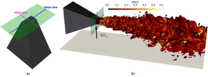
A rectangular supersonic jet that has been extensively tested at the University of Cincinnati [15–18] is selected for this numerical work. The nozzle has an aspect ratio of 2.0 with a convergent-divergent profile on the minor axis plane and a constant width on the major axis plane. The schematic of the nozzle is shown in Fig.1a. It has a design Mach number of 1.5 that corresponds to a nozzle pressure ratio (NPR) of 3.67 and a nozzle temperature ratio (NTR) of 1.0 in the cold flow condition.
In this study, a highly-heated jet operating at NPR of 3.0 and NTR of 7.0 is selected. The ambient pressure and temperature arePambient=101325 Pa andTambient=293 K. The plate is located perpendicularly to the jet minor axis plane. Four nozzle-to-plate distances are considered,L = 0, Deq, 2Deq, and 3Deq.Deqis the jet equivalent diameter that is computed by converting the rectangular nozzle into a round nozzle with the same nozzle exit area. The
nozzle-to-plate distance is measured from the nozzle inner lip in the minor axis plane, so thatL = 0 means the plate is directly attached and flush-mounted at the nozzle lip. These four cases will be referred to as JetL0, JetL1, JetL2, and JetL3 in the following. Fig.1billustrates the schematic of nozzle-plate configuration withL = 3Deq.
a) b)
Figure 1. Schematic of (a) the nozzle and (b) the nozzle-plate configuration ofL = 3Deqwith iso-surfaces of density (ρ = 0.7kg/m3)
representing the jet shear layer. The iso-surfaces of the jet are colored by local Mach numbers.
The NPR of the four jets is 3.0, corresponding to an over-expanded operating condition, in which both shock waves and expansion waves are expected inside the jet potential core. Furthermore, the current nozzle has a sharp throat and thus an additional set of shocks will be generated inside the nozzle and reflected outside to interact with the shock/expansion structures. Details of the nozzle operating conditions are shown in Table1. It can be seen from Table
1that due to the large NTR of 7.0, the corresponding ideally expanded jet temperatureTjand velocityuj both have large values. The ideally expanded Mach number of the jet in the selected operating condition is 1.39.
Table 1. Nozzle operating conditions.L is the distance between the plate and the nozzle lip; N P R is the nozzle pressure ratio; N T R is the nozzle temperature ratio;Mj,uj, andTjdenote ideally expanded Mach number, velocity, and static temperature of the jet.
Case L N P R T R Mj uj(m · s−1) Tj(K) JetL0 0 3.0 7.0 1.39 1070 1592 JetL1 Deq 3.0 7.0 1.39 1070 1592 JetL2 2Deq 3.0 7.0 1.39 1070 1592 JetL3 3Deq 3.0 7.0 1.39 1070 1592
In the high temperatures (e.g.>2000 K), air starts to dissociate and its composition changes. This can significantly affect the air properties (e.g. the specific heat ratioγ) and thus affect the flow and acoustic fields predicted by CFD. Based on Liu et al. [19], a temperature-dependent specific heat ratio is recommended for the numerical study of a highly-heated jet. Therefore, similar treatment is adopted here by considering the chemical equilibrium assumption. The temperature-dependent thermodynamic properties of air are pre-calculated and embedded into the CFD code as a look-up table. In this way, expensive chemical reaction calculations can be neglected [13]. Moreover, the temperature dependence of viscosityµ is estimated by using Sutherland’s law.
III.
Computational Methodology
A. Numerical methods
Simulations in this study are performed by using a compressible in-house flow solver [20]. It has been validated and implemented in our previous studies by Semlitsch et al. [21], Gojon et al. [10,22,23], and Chen et al. [13,14]. This code uses a finite volume method to solve the three-dimensional compressible Navier-Stokes equations with the implicit LES approach [24,25] in Cartesian coordinates.
In the current solver, an explicit standard four-stage Runge-Kutta algorithm is used for time integration and a second-order central difference scheme is used for spatial discretization. A modified Jameson-type [26,27] artificial dissipation is added to the flow at the end of each time step. This modified dissipation is designed to capture shocks
and to provide a non-oscillatory behavior of the second-order central difference scheme near sharp gradients. Details of the artificial dissipation term implemented in the study can be found in the work of Gojon et al. [23].
B. Computational domain and boundary conditions
The computational domain in the stream-wise direction is around 67h, and the radius of the domain in the plate reflected direction is larger than 21h, where h is the nozzle height in the minor axis plane. At the flow inlet, the total flow conditions are specified. The nozzle wall and plate are assumed to be adiabatic and non-slip. The surrounding of the computational domain is set as the characteristics boundary with ambient static pressure and temperature. Together with the usage of sponge zones, spurious reflections at the boundaries can be canceled.
The computational meshes are multi-block structured grids created by ANSYS ICEM CFD. They have around 150 million cells in total and are designed based on our previous grid-convergence study [22]. The grid points are clustered in the jet region where large flow gradients exist, and it is stretched slowly in both the axial and radial directions. It has a small first layer thickness with ay+
∼ 1 in the wall normal direction and x+, y+< 10 in the wall parallel directions within the diverging part of the nozzle. The growth ratio of the grid is controlled to stay below 5 % in each direction to avoid high dissipation or dispersion errors from the spatial derivation scheme. The large-scale LES computations are performed on 960 processors.
The current work is a continuation of our previous works [10,22,23], where the detailed grid convergence study, validation of the numerical method with experimental data of low-temperature jets with and without a plate are carried out and presented. Good agreements with the data from the experimental campaign at the University of Cincinnati [3,28] have been achieved for the low-temperature jets investigated.
IV.
Results and Discussion
A. Effects of a plate on jet flowfields
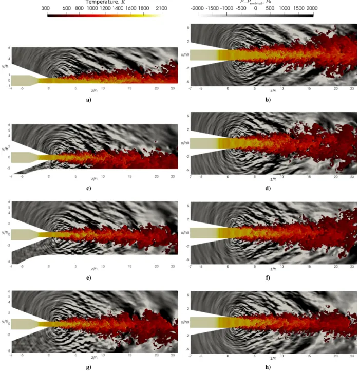
Instantaneous jet static temperature contours and near-field fluctuating pressure are presented in Fig.2. The jet has a static temperature around 1600 K at the nozzle exit. For JetL0 in which the plate is attached to the nozzle lip, the jet plume scrubs over the plate as shown in Fig. 2a. For JetL1, JetL2, and JetL3 as shown in Figs.2c,2e, and2g, a gap is formed between the jet and plate allowing the ambient air to flow through. Due to the Coanda effect, the jet plume inclines towards the plate. This behavior is especially visible for JetL1 in Fig. 2c. From the temperature contours on both the minor and major planes, it can be observed that the jet potential core in JetL0 is longer than that of the other jets. In the near-field pressure fluctuation fields, three main acoustic components can be seen. The first is the Mach wave radiation propagating downstream with an angle of about 130 degrees from the upstream direction [13]. This component is generated by large turbulent structures in the jet shear layer convected downstream at a supersonic speed. The second is the turbulent mixing noise, characterized by a low-frequency wave propagating close to the jet plume in the downstream direction. It is generated by the turbulent mixing process between the jet and ambient. The third component corresponds to the circular acoustic wave radiating from the jet shear layers at different axial locations. These acoustic waves are generated by the interactions between the shock waves inside the jet potential core and the shear layers. For JetL1 to JetL3 where a gap exists between the nozzle and the plate, acoustic waves reflected by the plate are also visible in the minor axis planes aty/h < 0.
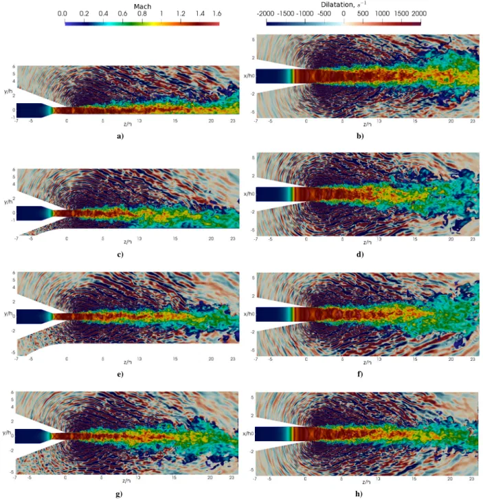
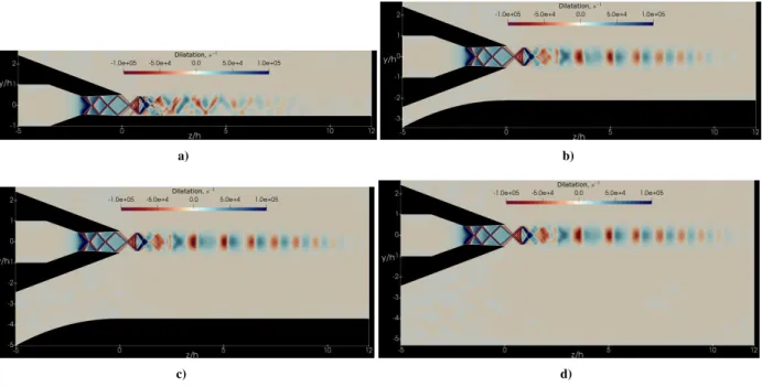
Instantaneous jet Mach number contours and the dilatation distributions in the near field are presented in Fig. 3. Dilatation is defined as the divergence of velocity. With the continuity equation, the dilatation can be expressed as a function of density as in the following form, representing the relative change in density of a fluid (or compressibility effect):
Dilatation = ∇ · u = −1 ρ
Dρ
Dt (1)
The dilatation contours in Fig. 3 show wave patterns in both the minor and major axis planes propagating along different directions. Similar to the previous pressure fluctuation contours in Fig.2, the large magnitudes of dilatation originating from the nozzle exit and propagating downstream in a cone shape indicate the existence of the Mach wave radiation. But differences can be observed from these wave patterns between the previous pressure fluctuation contours in Fig. 2 and the dilatation contours in Fig. 3. One should be noted that the pressure fluctuation and dilatation are two different quantities. Dilatation represents the compressibility effect associated with density, whereas the pressure fluctuation includes both the effect of density and temperature from the ideal gas law (p = ρRT ). In the current highly-heated supersonic jets, temperature gradients in the near field is a variable that can not be simply neglected. From the jet Mach number contours, similar to the findings from Fig. 2, a longer jet potential core in JetL0 can be seen clearly too.
a) b)
c) d)
e) f)
g) h)
Figure 2. Instantaneous temperature and acoustic pressure contours at the minor axis plane (a,c,e,g) and the major axis plane (b,d,f,h). (a,b) JetL0 (c,b)JetL1, (e,f)JetL2, and (g,h)JetL3.
a) b)
c) d)
e) f)
g) h)
Figure 3. Instantaneous jet Mach number and ambient dilatation contours at the minor axis plane (a,c,e,g) and the major axis plane (b,d,f,h): (a,b) JetL0 (c,b)JetL1, (e,f)JetL2, and (g,h)JetL3.
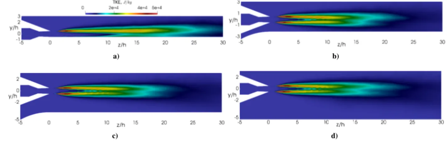
The time-averaged Mach number contours are shown in Fig. 4. In the minor axis plane, a white line aty/h = 0 is shown to illustrate the asymmetry of jet plumes. Indeed, in Figs. 4a,4c,4e, and4g, an asymmetric distribution of the Mach number can be observed along the minor axis plane. For JetL0 in Fig. 4a, it is because of the plate flush mounted at the nozzle lip. The shear layer that is supposed to develop in free jets is prohibited by the plate. This asymmetry can be seen fromz/h = 2 to the downstream. In JetL1 to JetL3 as shown Figs. 4c,4e, and4g, the jet symmetry approximately breaks atz/h = 15 ∼ 20 and the jet inclines towards the plate due to the Coanda effect. When the jet flows over the plate, the plate blocks ambient air below the plate coming towards the jet plume. Without this supplement air, a local low-pressure region is formed in the gap between the jet and the plate which will attract the jet plume towards the plate. This is why the jet bends towards the plate and loses its symmetry. In the major axis planes as shown in Figs.4b,4d,4f, and4h, no significant asymmetry is observed. Fig. 5shows the turbulent kinetic energy (TKE) contours in the minor axis plane. For JetL0 in Fig.5a, only one shear layer is formed in the minor axis plane with a length longer than other cases. For the other three cases, two shear layers exist and the top one has a
relatively larger magnitude than the bottom one close to the plate. This indicates the top shear layer decays faster.
a) b)
c) d)
e) f)
g) h)
Figure 4. Time-averaged Mach number contours at the minor axis plane (a,c,e,g) and the major axis plane (b,d,f,h): (a,b) JetL0 (c,b) JetL1, (e,f) JetL2, and (g,h) JetL3. White lines aty/h = 0 in the minor axis plane and x/h = 0 in the major axis plane are shown to indicate the nozzle center-line location.
a) b)
c) d)
Figure 5. Turbulent kinetic energy (TKE) contours at the minor axis plane (a,c,e,g) and the major axis plane (b,d,f,h): (a,b) JetL0 (c,b) JetL1, (e,f) JetL2, and (g,h) JetL3.
The time-averaged Mach number profiles along the nozzle center-line are plotted in Fig. 6. The Mach number profiles are almost identical for JetL1, JetL2, and JetL3. The Mach number increases from subsonic inside the nozzle (z/h < 0) to supersonic speeds, oscillates and then decays to subsonic in the downstream. The ups and downs in the profiles represent the shock-expansion wave structures occurring inside the nozzle divergent part and the jet potential
core. Outside the nozzle(z/h > 0), eight shock cells are formed. In comparison, JetL0 exhibits a different profile without obvious peaks and pits. Again, as observed in the previous flow fields snapshots, a longer jet potential core can be seen from the Mach number profile for JetL0.
Figure 6. Time-averaged Mach number distributions along the nozzle’s center-line atx/h = y/h = 0.
a) b)
c) d)
Figure 7. Shock/expansion wave structures represented by the time-averaged dilatation at the minor axis plane: (a) JetL0 (b)JetL1, (c)JetL2, and (d)JetL3.
Fig.7shows the time-averaged dilatation contours of the four jets on the minor axis plane. The dilatation represents expansion and compression regions in the flow fields. In Fig. 7, the large negative values in red color mean strong compression indicating shock waves, where the large positive values in blue color mean flow expansion suggesting expansion regions. In Figs.7b,7c, and7d, the shock diamonds in red outside the nozzle can be seen clearly. However, this shock diamonds pattern is not visible in JetL0 as shown in 7a. Only one shock cell atz/h =∼ 1 is visible. As discussed earlier, the existence of the plate attached to the nozzle lip in JetL0 prohibits the jet to expand in the confined direction. In the other three cases, the shock/expansion waves are reflected inside the jet core by the shear layer surrounding it. Within the length of the jet core (roughly fromz/h = 0 ∼ 10), good symmetry of the jet potential core is obtained in the three cases as it can be seen in Figs. 4c,4e, and4g. However, in JetL0 the shock/expansion waves are reflected by the shear layer at one side and the rigid parallel plate on the other side, which destroys the wall jet’s symmetry on the minor axis plane. Therefore, the well-structured shock cell patterns are not present in JetL0.
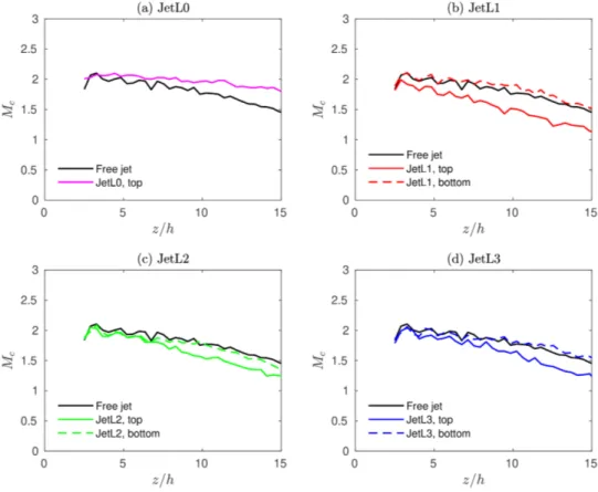
The convection Mach number of the turbulent structures in jet shear layers can be linked with the Mach wave radiations. Point probes are inserted along the nozzle lip fromz/h = 0 ∼ 15 at y/h = ±0.5. The flow data at these locations are recorded during the computations. By using cross-correlation, the convection Mach number of the shear layers is computed. The convection Mach numberMcis defined as
Mc= uc a0
(2) whereucis the convection velocity of the turbulent structures anda0is the ambient speed of sound.
The convection Mach numbers of the top and bottom shear layers in the minor axis plane are shown in Fig.8. The results of the free jet from our previous work [13] are also shown for comparison purposes. The profiles of convection Mach number experience a slight decay along thez direction mainly due to the jet’s mixing with the ambient air. The saw shapes in each of the profiles are caused by the corresponding shock cell patterns in the jet core. In JetL0 as shown in Fig.8a, only one shear layer is generated along the minor axis plane. The convection Mach number of this top shear layer is around 2.0 and is about 10% larger than that of the free jet. In the other cases, two shear layers exist in the minor axis plane as mentioned earlier: one on the top and the other on the bottom. The difference between the two are obvious especially in Figs.8b. The convection Mach number of the bottom shear layer is roughly the same as the free jet but is about 10 ∼15% larger than the top one. This is consistent with the previous finding in TKE contours as shown in Fig.5in which the top shear layers decay faster.
B. Effects of a plate on jet aeroacoustics
a) b)
c) d)
e) f)
g) h)
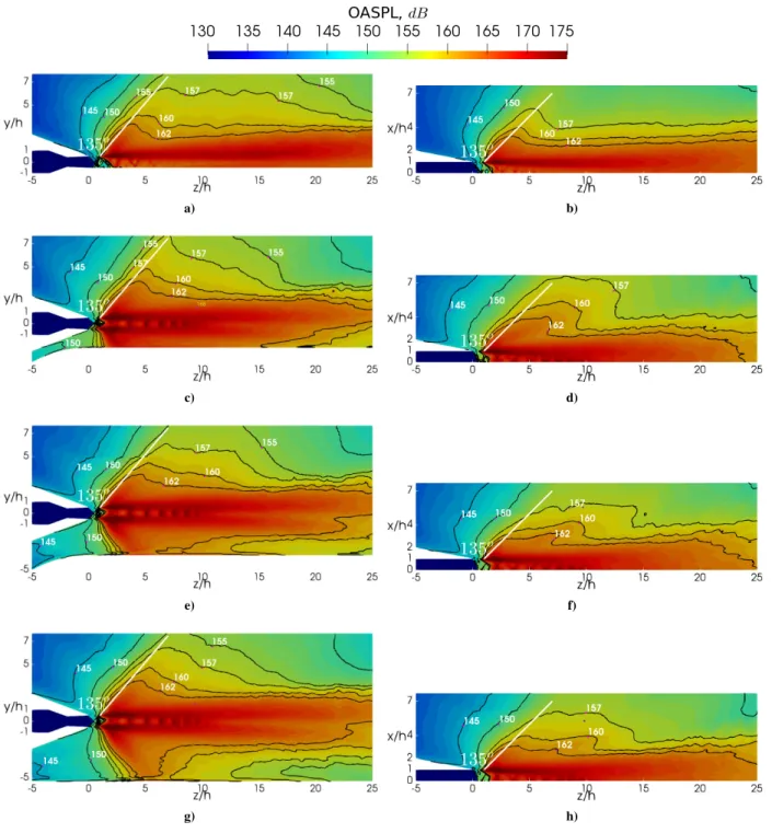
Figure 9. OASPL contours at the minor axis plane (a,c,e,g) and the major axis plane (b,d,f,h). (a,b) JetL0 (c,b)JetL1, (e,f)JetL2, and (g,h)JetL3. Note that only half of the major axis plane is shown in (b,d,f,h).
Overall sound pressure levels (OASPL) in the near field of the jet are presented in Fig. 9on both the minor and major axis planes. The OASPL is defined as:
OASP L = 20 × log(Prms Pref
) dB (3)
wherePrmsis the root mean square of sound pressure andPrefis the reference sound pressure2 ×10−5P a. In Fig.9, the acoustic component of Mach wave radiation is visible in both the minor and major axis planes. It is characterized by large OASPL magnitudes with a strong directionality along about 135 degrees from the upstream direction. The
direction of 135 degrees is marked by a white line in Fig.9for a reference. Two findings can be obtained by tracking the contour lines, say 157dB, on these plots. The first is the Mach wave radiation in the minor axis plane is stronger than that in the major axis planes for each case respectively. Secondly, when the plate is moved away from the jet from JetL0 to JetL3, the acoustic power first increases and then decreases slightly. Among the four cases, JetL1 has the maximum acoustic power. This can be seen from the location of the contour line of 157dB in both the minor and major axis planes. Recalling the flow field results in Fig. 2, this is probably due to case JetL1 not only has two well-developed shear layers where strong shock-shear layer interactions occur but also maintain a jet-plate interaction where the “scrubbing” effect exists. Meanwhile, among the three cases of JetL1 to JetL3, the plate in JetL1 is closest to the nozzle. The plate reflection effects would also be the strongest. The combination of shock-shear layer interactions, jet-plate “scrubbing”, and the plate reflection contributes to the largest acoustic power in JetL1.
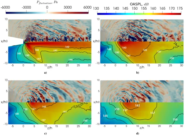
Snapshots of the fluctuating pressure distributions and the corresponding OASPLs on the plate are depicted in Fig. 10for the four cases respectively. The jet “scrubbing” effects characterized by chaotic hydrodynamic pressure fluctuations can be seen in JetL0 (fromz/h > 0 in the top of Fig.9a) and JetL1 (fromz/h > 15 in the top of Fig.9c). Differently, the plate pressure distributions of JetL2 and JetL3 are similar to the near acoustic fields discussed earlier without apparent scrubbing effects. From the magnitude of the fluctuating pressure, JetL0 and JetL1 show apparent larger amplitudes among the four cases, which indicates the reflection effects in JetL1 are stronger than the other two. The OASPLs of the plate in four cases are illustrated in the bottom halves of Fig. 10. If tracking the contour line of 157dB, it can be seen that the JetL0 has the largest loading on the plate.
a) b)
c) d)
Figure 10. Instantaneous pressure fluctuations (top half) and OASPLs (bottom half) on the plate for: (a) JetL0 (b)JetL1, (c)JetL2, and (d)JetL3.
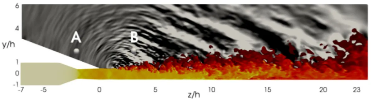
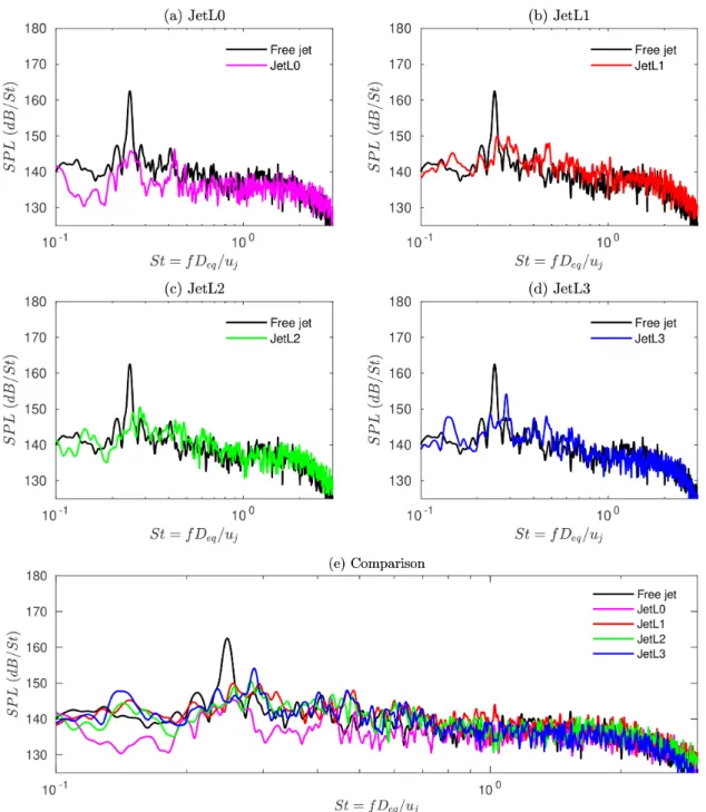
Two point probes are placed on the minor axis plane as depicted in Fig. 11. One is located upstream of the jet: point A at (x/h, y/h, z/h)= (0, 2, −2) and the other is located downstream along the direction of the Mach wave radiation: point B at (x/h, y/h, z/h)= (0, 2, 3). Acoustic spectra of the four cases at point A are presented against Strouhal numberSt = f Deq/uj in Fig.12. f is frequency and uj is the ideally expanded jet velocity which is 1070 m/s for the cases presented in this work. For comparison purposes, the acoustic spectrum of the corresponding free jet
is also plotted and shown in black. The free jet spectrum is characterized by a strong screech tone with an amplitude of 163dB at St = 0.25. For JetL0 in Fig.12a, the plate attached at the nozzle lip changes the spectrum and provides a low-amplitude profile in the low-frequency range atSt = 0.1 ∼ 1.0. There are two peaks at St = 0.25 and 0.43 respectively, but with a smaller amplitude of around 146dB that is about 15 dB lower than the screech tone in the free jet. When the plate is moved away from the jet, their spectra become similar to that of the free jet but they are still lack of the strongly dominant screech tone. JetL3 as shown in Fig.12estarts to show a dominant peak of 154dB atSt = 0.29, but it is still 9 dB lower than the screech tone the free jet. Compared with JetL0, when the plate is away from the jet, there is a visible increase of amplitude in the low-frequency range fromSt = 0.1 ∼ 1.0, as shown in Fig.
12e.
Figure 11. Schematic of the location of two probes: A (x/h, y/h, z/h)= (0, 2, −2) and B (x/h, y/h, z/h)= (0, 2, 3).
Acoustic spectra at point B in the direction of Mach wave radiation are presented in Fig.13. As shown in Figs.13a ∼ d, the spectrum in each case is similar to that of free jet in black but without a dominant peak in the low-frequency range (i.e. the peak of 173dB at St = 0.25 corresponding to the screech frequency). Instead, they possess a small peak at a higher frequency. For example as shown in Figs. 13b ∼ d, JetL1, JetL2 and JetL3 have peaks of 172dB, 170dB, and 169 dB respectively at St = 0.6. Furthermore, JetL1 as shown in Figs. 13balso presents an increase of amplitude at the frequency range ofSt = 0.4 ∼ 1.2 among the four cases. This is consistent with the finding obtained from9where JetL1 has the largest OASPLs along the direction of Mach wave radiation.
V.
Conclusions
Through implicit LES computations, a highly-heated rectangular supersonic jet is studied under the effect of an adjacent flat plate. Four jet-to-plate distances ranging from 0 to 3 times of jet equivalent diameterDeq, are investigated. Among the four cases, JetL0 in which the plate is directly attached at the nozzle lip show significant differences with others in both flow and acoustic fields. In JetL0, the jet plume is scrubbing over the plate right from the nozzle exit and has a longer jet potential core length. The existence of plate prohibits the jet to expand towards the confined direction. The shock/expansion waves inside the jet core reflects asymmetrically within the top shear layer and the bottom parallel wall on the minor axis plane without forming a series of well-structured shock diamonds. In the other cases instead, the shock diamonds are formed in a way very similar to the free jet. However, Coanda effect is associated with jet plume inclining towards the plate. This bending of the jet leads JetL1 to scrub over the plate in the downstream. The scrubbing effect, together with the unaffected shock-shear layer interactions and a larger plate pressure loading, leads JetL1 have a larger acoustic power than the other cases. The spectrum analysis in the nozzle upstream direction shows that the plate removes the screech tone observed in the free jet and slightly amplifies the acoustic amplitudes in the low-frequency range. The spectrum analysis in the downstream direction along the Mach wave radiation shows a slight increase of broadband shock associated noise except for JetL0.
For the screen tone, in our previous work [10] which used the same jet parameters but focused on the low-temperature jet, JetL0 also presented that the screech was removed when the plate is flush-mounted to the nozzle lip. However, different from our current findings in high-temperature jets, the screech tones were still observed in JetL1 to JetL3 when the plate is away from the nozzle. This interesting phenomenon would need further investigations.
Figure 13. Acoustic pressure spectra at the downstream of the nozzle along the Mach wave radiation direction: point B at (x/h, y/h, z/h)= (0, 2, 3). The dash line represents St = 0.6.
Acknowledgments
The computations were performed on resources provided by the Swedish National Infrastructure for Computing (SNIC) at PDC Centre for High-Performance Computing (PDC-HPC).
References
[1] Lazzara, D. S., Magee, T., Shen, H., and Mabe, J. H., “Off-Design Sonic Boom Performance for Low-Boom Aircraft,” AIAA Paper, 2019-0606, 2019.
[2] Hill, G. A. and Thomas, R. H., “Challenges and Opportunities for Noise Reduction through Advanced Aircraft Propulsion Airframe Integration and configurations,” 8th CEAS Workshop on Aeroacoustics of New Aircraft and Engine Configurations, Budapest, Hungary, 2004.
[3] Mora, P., Baier, F., Kailasanath, K., and Gutmark, E. J., “Acoustics from a Rectangular Supersonic Nozzle Exhausting over a Flat Surface,” The Journal of the Acoustical Society of America, Vol. 140, No. 6, 2016, pp. 4130–4141.
[4] Brown, C. A., “Jet-Surface Interaction Test: Far-Field Noise Results,” Journal of Engineering for Gas Turbines and Power, Vol. 135, No. 7, 2013, pp. 071201.
[5] Brown, C. A., Clem, M. M., and Fagan, A. F., “Investigation of Broadband Shock Noise from a Jet Near a Planar Surface,” Journal of Aircraft, Vol. 52, No. 1, 2015, pp. 266–273.
[6] Yu, J. and W. Tam, C., “Experimental Investigation of the Trailing Edge Noise Mechanism,” AIAA Journal, Vol. 16, No. 10, 1978, pp. 1046–1052.
[7] McLaughlin, D., Kno, C.-W., and Papamoschou, D., “Experiments on the Effect of Ground Reflections on Supersonic Jet Noise,” AIAA Paper, 2008-22, 2008.
[8] Liu, J., Corrigan, A., Kailasanath, K., Ramamurti, R., Heeb, N., Munday, D., and Gutmark, E., “Impact of Deck and Jet Blast Deflector on the Flow and Acoustic Properties of an Imperfectly Expanded Supersonic Jet,” Naval Engineers Journal, Vol. 127, No. 3, 2015, pp. 47–60.
[9] Stich, G.-D., Housman, J. A., Kocheemoolayil, J. G., Kiris, C. C., and Bridges, J. E., “Hybrid RANS/LES Simulation of Jet Surface Interaction Noise,” AIAA Paper, 2019-2475, 2019.
[10] Gojon, R., Gutmark, E., and Mihaescu, M., “On the Response of a Rectangular Supersonic Jet to a Near-Field Located Parallel Flat Plate,” AIAA Paper, 2017-3018, 2017.
[11] Tinney, C. E., Panickar, P., and Vogel, P., “Aeroacoustics of a Planar Multistream Supersonic Nozzle with Aft Deck and Sidewalls,” AIAA Journal, Vol. 56, No. 10, 2018, pp. 3926–3937.
[12] Baier, F., Karnam, A., and Gutmark, E., “Near-field Measurements of a Low Aspect Ratio Supersonic Nozzle Interacting with a Surface,” AIAA Paper, 2019-1302, 2019.
[13] Chen, S., Gojon, R., and Mihaescu, M., “High-Temperature Effects on Aerodynamic and Acoustic Characteristics of a Rect-angular Supersonic Jet,” AIAA Paper, 2018-3303, 2018.
[14] Chen, S. and Mihaescu, M., “Nozzle Pressure Ratio Effects on Aerodynamics and Acoustics of a Highly-Heated Rectangular Supersonic Jet,” AIAA Paper, 2019-2753, 2019.
[15] Heeb, N., Mora, P., Gutmark, E., and Kailasanath, K., “Investigation of the Noise from a Rectangular Supersonic Jet,” AIAA Paper, 2013-2239, 2013.
[16] Baier, F., Mora, P., Gutmark, E. J., and Kailasanath, K., “Flow Measurements from a Supersonic Rectangular Nozzle Ex-hausting Over a Flat Surface,” AIAA Paper, 2017-0932, 2017.
[17] Karnam, A., Baier, F., Gutmark, E. J., and Kailasanath, K., “Flow Measurement and Acoustic Investigation of High Temper-ature Rectangular Jets,” AIAA Paper, 2018-0260, 2018.
[18] Karnam, A., Baier, F., and Gutmark, E. J., “Near Field Acoustic Analysis of Cold Supersonic Rectangular Jets,” AIAA Paper, 2019-0809, 2019.
[19] Liu, J., Corrigan, A., Kailasanath, K., and Taylor, B., “Impact of the Specific Heat Ratio on Noise Generation in a High-Temperature Supersonic Jet,” AIAA Paper, 2016-2125, 2016.
[20] Eliasson, P., “EDGE: A Navier-Stokes Solver for Unstructured Grids,” 2001.
[21] Semlitsch, B., Cuppoletti, D. R., Gutmark, E. J., and Mihaescu, M., “Transforming the Shock Pattern of Supersonic Jets Using Fluidic Injection,” AIAA Journal, Vol. 57, No. 5, 2019, pp. 1851–1861.
[22] Gojon, R., Baier, F., Gutmark, E., and Mihaescu, M., “Temperature Effects on the Aerodynamic and Acoustic Fields of a Rectangular Supersonic Jet,” AIAA Paper, 2017-0002, 2017.
[23] Gojon, R., Gutmark, E., and Mihaescu, M., “Antisymmetric Oscillation Modes in Rectangular Screeching Jets,” AIAA Journal, Vol. 57, No. 8, 2019, pp. 3422–3441.
[24] Fureby, C. and Grinstein, F., “Monotonically Integrated Large Eddy Simulation of Free Shear Flows,” AIAA Journal, Vol. 37, No. 5, 1999, pp. 544–556.
[25] Margolin, L. G. and Rider, W. J., “A Rationale for Implicit Turbulence Modelling,” International Journal for Numerical Methods in Fluids, Vol. 39, No. 9, 2002, pp. 821–841.
[26] Jameson, A., Schmidt, W., and Turkel, E., “Numerical Solution of the Euler Equations by Finite Volume Methods Using Runge-Kutta Time-Stepping Schemes,” AIAA Paper, 1981-1259, 1981.
[27] Ducros, F., Ferrand, V., Nicoud, F., Weber, C., Darracq, D., Gacherieu, C., and Poinsot, T., “Large-Eddy Simulation of the Shock/Turbulence Interaction,” Journal of Computational Physics, Vol. 152, No. 2, 1999, pp. 517–549.
[28] Mora, P., Baier, F., Gutmark, E. J., and Kailasanath, K., “Acoustics from a Rectangular C-D Nozzle Exhausting over a Flat Surface,” AIAA Paper, 2016-1884, 2016.