HAL Id: hal-01102158
https://hal.archives-ouvertes.fr/hal-01102158
Submitted on 12 Jan 2015
HAL is a multi-disciplinary open access
archive for the deposit and dissemination of
sci-entific research documents, whether they are
pub-lished or not. The documents may come from
teaching and research institutions in France or
abroad, or from public or private research centers.
L’archive ouverte pluridisciplinaire HAL, est
destinée au dépôt et à la diffusion de documents
scientifiques de niveau recherche, publiés ou non,
émanant des établissements d’enseignement et de
recherche français ou étrangers, des laboratoires
publics ou privés.
Enactment of Components Extracted from an
Object-Oriented Application
Abderrahmane Seriai, Salah Sadou, Houari Sahraoui
To cite this version:
Abderrahmane Seriai, Salah Sadou, Houari Sahraoui. Enactment of Components Extracted from
an Object-Oriented Application. European Conference on Software Architecture (ECSA), Aug 2014,
Viena, Austria. pp.234 - 249, �10.1007/978-3-319-09970-5_22�. �hal-01102158�
Abderrahmane Seriai1, Salah Sadou1, and Houari A. Sahraoui2
1 Universit´e de Bretagne Sud, IRISA, Vannes, France
{abderrahmane.seriai,Salah.Sadou}@irisa.fr
2 Universit´e de Montr´eal, DIRO, Montr´eal, Canada
Software architecture plays an important role for the application understanding be-fore its maintenance. Unfortunately, for legacy systems code often there is no corre-sponding (or up to date) architecture. So, several work tackle this problem by extracting components from the legacy system and define their links. Although these components allow to get an architectural view of the legacy system, they still can’t be easily im-plemented in a concrete framework. In fact, restructuring completely the legacy system facilitates the mapping between the architectural elements and their corresponding ones in the code. This paves the way to the future maintenance of the system.
Our approach aims to reach this complete restructuring. Thus it goes beyond what exists in the state of the art by proposing a technique that makes components extracted from object-oriented applications implementable within a concrete component model. This is done by using class instances that compose the extracted components to infer possible instances the components. Thus, we propose for each extracted component its provided and required interfaces, and a way to construct its instances. We validated the feasibility of the proposed approach through the Spring framework and we illustrated it through a legacy Java application.
1
Introduction
Most existing works on extraction of components from a legacy system have as a main aim the construction of an understandable architecture [10,17,2]. When the legacy sys-tem is implemented in the object-oriented paradigm, a component is represented by a cluster of classes with a set of provided methods and a set of required methods. Thus, the identification of the components consists in finding the groups of classes that are the most cohesive and loosely coupled. So, the obtained results have the advantage to offer a more abstract representation via a component-oriented architecture view of the object-oriented application.
The extracted software architecture facilitates the understanding of the legacy sys-tem. However it needs to be complemented by a mapping between architectural ele-ments and their corresponding ones in the code in order to facilitate the achievement of maintenance. In fact, sets of classes, representing components, can not be easily pro-jected onto a specific component model [2]. This problem is due to the shift from the concept of object instances to the concept of component instances. Indeed, it is not easy to infer a component instances from a set of class instances. Hence, the executable
version of the application remains in its old form and therefore has no direct corre-spondence with the architecture. Consequently, there is no direct mapping between the architecture and the running application.
To solve this problem, we need to be able to project the extracted components on a concrete component model. This will give the advantage of creating a direct mapping between architectural elements and their equivalents in the code of the application. To achieve this purpose, we need to (i) identify the interfaces of the extracted components to make them consistent with the component paradigm concepts, and (ii) determine how the concerned classes will be instantiated with respect to component instances. This second concern, which is neglected in literature on component extraction, is im-portant as it allows to formalize the notion of component instance, which is necessary to make the application executable and at the same time its components reusable by others applications.
In a recent work [16], we proposed a solution for the point (i) based on a static anal-ysis of the extracted components. In this paper, we propose a solution for the point (ii). Our approach considers that the extraction of components (cohesive groups of classes) is already performed. It is based on the hypothesis that an instance of a component consists of a connected set of instances of its classes. Thus, the objective is to iden-tify all instances of classes representing an instance of a component in order to build the component’s factory. This will provide the necessary means for the framework to run the restructured application. Furthermore, the identification of the component in-stances allows us to propose a dynamic approach to the identification of the component interfaces.
To demonstrate the feasibility of our approach, we present its implementation within the Spring component framework. After that, we apply it on a Java application that we restructured into a component-based application with the approach presented in [2]. To validate the correction of the restructuring, we have replayed the application’s case studies on its component-based version and the results were identical to those of its object-oriented version.
The rest of the paper is organized as follows: in the next section we describe the process of our approach. Sections 3 shows how to define instances of a component starting from the objects of its classes. Then, the definition of the component’s inter-faces and the creation of its instances is described in Section 4. In Scetion 5 we show how our approach can be implemented using the Spring component framework. Before concluding, we present the related work in Section 6.
2
Approach
The group of classes, which represents a component, are part of the definition of the component descriptor. The descriptor of a component is equivalent to the class in the object-oriented paradigm. Thus, what is lacking with the group of classes is the way to build instances of the component. Indeed, to create a component-based application, as in the case of an object-oriented application, it requires creating component instances and binding them.
Fig. 1. Process of the proposed approach.
Definition 1 : An instance of a component consists of all instances of its classes, which have had connections during the execution of the application and thereby forming a connected group.
Objects surrounded by a dashed line in figure 3 is an example of component in-stance. To build component instances, we must first identify the instances of classes that compose them and their links. This is why our approach, as shown in Figure 1, begins with the execution of the application’s use cases in order to extract traces of method calls between objects. This information will be summarized in an object call graph (step 1 of the process).
The use of the application’s use cases is a way to get only objects that actually play a role in the functionalities provided by the system. Thus, all the other objects from classes held by the application are naturally avoided and have no chance to infer in the proposed process.
By analysing all objects, instances of classes belonging to the same component, we can find several connected groups. It is these groups of objects that represent instances of the component. Thus, we can reduce the obtained object call graph to a component call graph in order to focus on the relationships between component instances (step 2 of the process).
The identification of component instances is interesting only to deduce a way to build them. For a given component, some of its instances may have similarities when considering the type of their involved objects. Thus, these component instances suggest a common constructor. Indeed, these component instances have a similar configuration of their constituent objects that we define as follows:
Definition 2 : Two instances of the same component belong to the same configuration if and only if their subsets of objects, which are directly concerned by the compo-nent’s incoming calls, are similar.
Definition 3 : Two sets of objects are similar if and only if they contain the same num-ber of class instances for each involved class.
Finding all possible instance configurations for each component is the goal of the step 3 of our process. Once the possible instance configurations of a component are identified, we need to define a constructor for each of them. Subsequently, to each configuration of instances, we associate a component provided interface (goal of the step 4). Thus, with our approach, each component interface highlights one of its aspect, which is emerged by the configuration. For a component, its required interfaces will be defined according to the identified provided interfaces of all components on which it depends.
In the following sections, we describe each step of our approach.
3
From Object to Component Call Graph
An important step in our approach is to identify component instances, and their bind-ings, by considering the classes they hold. The component instances will consist of objects from its classes. For this aim, we first construct an object call graph in order to transform it into a component instance call graph.
3.1 Object Call Graph
The first step of our approach consists of identifying all possible class instances for the entire application and build their links. This leads to the construction of a call graph specific to class instances (objects).
To get this call graph, we run the application with all its use cases to capture the execution traces. An execution trace corresponds to a directed tree T(V, E) where V is a set of nodes and E a set of edges between nodes. Each node Virepresents an instance
of the class (Cli). An edge hVi, Vji indicates that an instance i calls a method of an
instance j. The root of T(V, E) corresponds to the entry point of the system.
As shown in Figure 2(left), the nodes of the tree are labeled by the identifier, the actual types of the objects that are called and the concerned methods. As the execution traces are based on method calls, it is possible to have nodes containing the same object (same identifier) with calls on different methods. This is the case for object d0 which appears twice for two different methods (see left part of Figure 2). So, these nodes are grouped in the same one in order to get a graph where each object is represented by exactly one node. Thus, the resulting node contains all called methods. An example of such a transformation is given in the right part of Figure 2. The resulting graph corresponds to what we call Object Call Graph (OCG).
a0:A b0:B mth1 c0:C mth2 d0:D mth3 d0:D mth4 h0:H mth7 e0:E mth5 f0:F mth6 b1:B mth8 a0:A c0:C mth2 d0:D mth3, mth4 h0:H mth7 e0:E mth5 f0:F mth6 b0:B mth1 b1:B mth8
Fig. 2. Example of execution trace tree (left) and its corresponding object call graph (right).
3.2 Component Call Graph
The identification of component instances is based on our definition of component in-stance (see Section 2). Thus, starting from the OCG of an application, we need to iden-tify the sub-OCG that may be associated with each component. Recall that our working hypothesis is that for each component, we know the classes composing it. Thus, finding the sub-OCG associated with a component leads to find the sub-OCG composed of all objects that are associated with the component.
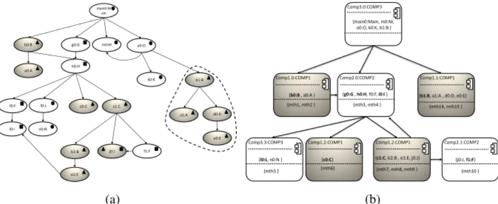
Figure 3 (left side) shows examples of such a sub-OCG. Objects associated with the same component are marked with the same symbol (circle, triangle or square). For in-stance, the dimmed objects are associated with the same extracted component (triangle symbol), which holds the classes A, B, C, D, E and J. When an object is marked with several symbols, it means that it is used inside several components and thus, its class is used to define these components. This situation arises when components ex-change object references through service calls. We will discuss the responsibility of creating this kind of objects in the next section.
By analyzing the OCG of a component, we can identify graphs. These sub-graphs correspond to possible instances of the component. Figure 3 (right side) pro-vides a representation of the OCG that is reduced to component instances. That is what we call Component Call Graph (CCG). Thus, in a CCG, nodes are instances of com-ponents, and edges correspond to calls between components. In other words, edges correspond to calls between objects belonging to different components. For example, instances of the component represented by the dimmed sub-OCG in the right part of Figure 3 are shown as dimmed nodes in the right part of the same figure. One of these instances is Comp1.1, which contains objects a1, b1, d0 and e0. The listed meth-ods (mth14, mth15) are those called on these objects by instances of other
compo-e0:E d0:D a1:A c1:C b2:B e1:E b0:B c0:C m0:M k0:K o0:O l0:L main0:M ain n0:N f1:F g0:G h0:H f0:F i0:I b1:B j0:J a0:A Comp3.0:COMP3 {l0:L, n0:N } Comp3.3:COMP3 {c0:C} Comp1.2:COMP1 {b0:B , a0:A } Comp1.0:COMP1 Comp2.0:COMP2 {j0:J, f1:F} Comp2.1:COMP2 Comp1.1:COMP1 Comp1.2:COMP1 {mth1, mth2 } {mth3, mth4 } {mth5 } {mth6} {mth7, mth8, mth9 } {mth10 } {mth14, mth15 } {main0:Main, m0:M, o0:O, k0:K, b1:B } {c1:C, b2:B , e1:E, j0:J} {g0:G , h0:H, f0:F, i0:I } {b1:B, a1:A , d0:D, e0:E}
(a) (b)
Fig. 3. (a) Example of sub-OCG, (b) Example of component call graph.
nents. To each method name mthi, are associated the full method signature and the class to which it belongs.
In the case of an object that is shared by several component instances, all calls to (or from) this object, and coming from (or to) other objects held by these components, are considered internal and therefore, not visible at the CCG level. For example, in the OCG of Figure 3, the object j0 belongs to two component instances of different types (square and triangle). Thus, the call from c1 to j0 is considered internal to the component instance of triangle type and the call from f1 to j0 is considered internal to the component instance of square type. This is why in the corresponding CCG (right part of the figure) there is no edge between the component instances Comp2.1 and Comp1.1.
4
Interface Identification
By analyzing the instances of a component, we can identify similar configurations of objects they contain. According to the definition given in Section 2, component’s con-figurations help in defining its provided interfaces. At the same time, a configuration of a component reflects one of its aspects. Thus, we can also use the configuration to define a constructor for the component.
In the following, we describe our approach to identify configurations of a compo-nent as well as the constructors associated with them.
4.1 Configuration Identification
In Figure 3, the two instances Comp1.0 and Comp1.1 of component COMP1 have in common the fact that their accessible objects from outside (other components) are of the same type (b0 and b1 of type B and shown in bold). Thus, these component instances are associated with the same configuration. This configuration is characterized by the fact of exposing an object of type B as an interface to other components.
The two component instances, which have given rise to this configuration, show that only the methods mth1, mth2, mth14, and mth15 of the class B are used by the other components. Moreover, one of the two instances of the component (Comp1.0) requires an instance of another component (Comp2.0). As the latter belongs to a given configuration, so we can link the dependency to this configuration.
Thus, we define a configuration as a triple (ObjInt, MethInt, ReqConf) where: ObjInt corresponds to a set of objects belonging to component instances of the
con-figuration, which are called by other component instances.
MethInt corresponds to the union of sets of methods from component instances of the configuration that other component instances use.
ReqConf is the set of configurations of component instances that are required by those of the current configuration.
For instance, the configurations of the component given in the example above cor-respond to the following triplets:
({b0:B,b1:B},{mth1,mth2,mth14,mth15},{configuration1 of COMP2}) and
({c0:C,c1:C},{mth6,mth7,mth8,mth9},{configuration1 of COMP2})
From a configuration of a component, we can deduce one of its provided interfaces and some of its required interfaces. Indeed, the list of methods associated with the con-figuration correspond to a provided interface of the component. Thus, each provided interface is associated with one and only one configuration of the component. Further-more, as the configuration requires configurations from other components, the provided interfaces associated with those configurations define the required interfaces of the tar-geted component.
Thus, the provided interfaces of a component correspond to the set of provided interfaces suggested by its configurations. And its required interfaces correspond to the union of the provided interfaces associated with the configurations required by its configurations. From the example given above, we deduce the following required and provided interfaces:
Provided interfaces = {{mth1,mth2,mth14,mth15}, {mth6,mth7,mth8,mth9}} Required interfaces = {{mth3,mth4}}.
From the list of objects held by a configuration, we can also define the necessary con-structors for the component instances associated with this configuration. We will show that in the next sub-section.
4.2 Component Constructors
With the notion of configuration, we have grouped a set of component instances around the same provided interface. Although these instances are used through the same types of objects, the way to create them is not necessarily the same.
Indeed, each object can have different constructors that can be used independently to create component instances associated with the same configuration. Thus, we must
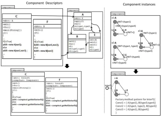
Component Descriptors Component instances <INIT>(type1) <INIT>(type1, type2) <INIT>(type4) <INIT>(type6) <INIT>() <INIT>(type1) <INIT>(type4) <INIT>() a1:A a2:A a3:A b3:B b2:B b1:B e1:E e2:E e3:E <INIT>(type3,type4) Interf1
Fig. 4. Example of transformation of object constructors into a Factory method pattern.
consider each component instance to analyse calls to constructors of its objects that are directly concerned with the provided interface. The objectives of this analysis are: (i) Identify objects whose construction is made by other components. (ii) Determine the precedence of creating these objects. iii) Determine the different combinations of constructors that are used to construct these objects.
Indeed, we are only interested in objects that are created outside of the component as the other objects are necessarily created by objects from the same instance component (connected graph).
Figure 4 shows a component (Component1) that requires an interface of another component (Component2). This interface concerns only objects of types A and B. When tracing the different use cases, we distinguish three instances of component Component2that are associated with this interface (see the right part of the figure). We note that the objects concerned by the interface were created by using different combinations of their constructors.
The different combinations of object constructors are grouped as a Factory method pattern. This pattern allows the construction of the various component instances that are associated with the same configuration (required interface). Thus, each provided inter-face of a component is associated with a Factory method pattern for the construction of component instances to be used through this interface.
Calls to object constructors of a component instance are actually dispersed in the component that uses this instance. Recall that each component instance is associated with a given provided interface. Thus, a component that uses a component instance will require an interface of the same type to which the component instance is associated with. Therefore, any references to objects of the component instance that is in the user component, must be transformed into a single reference to the component instance.
In the left part of Figure 4, component instances of Component1 use component instances of Component2 through object references (aAtt and bAtt) of type A and B. The type of these references must be replaced by the type of the required interface (Interf1). Moreover, these references must be initialized with the same component instance. This implies that each component instance holds its own identification, which will be communicated to all the objects that constitute it. This is equivalent to the this attribute in the object paradigm. As shown in Figure 4, the component’s classes will be changed in order to add a reference to the component instance as an attribute and a parameter in their constructors for initializing this attribute. The propagation of the identifier of a component instance to all objects that constitute it will be initiated by its associated Factory method pattern. Objects shared by different component instances (necessarily from different components) will receive the identifier of the component instance that created them.
Thus, calls to constructors of objects belonging to the required component instance will be replaced by a request of required component instance from the component in-stance to which the object belongs. As shown in the class F of Figure 4, bAtt = new (var1, var2)is replaced by bAtt = compInst.getRef1Interf1(). This implies that in the component descriptor, there is a getter method for each required interface.
The call to the Factory method of the provided interface of a component can be set in the component that requires this interface as it can be placed outside all components and thus constitute the configuration file of the application. The choice of the con-crete implementation of the Factory method pattern depends on the targeted component framework. In the following section, we give a solution within the Spring component framework.
5
Case Study
The objective of our approach is to make components extracted from an object-oriented application projectable on a concrete component model. Thus, we chose the case of Spring as a concrete model and framework. Our approach relies on the existence of extracted components represented by sets of classes. In the past we had done this work on a concrete application called Logo.
Below we give a brief description of the Logo application, followed by the tools developed for the implementation of our approach and we conclude by showing how the components are projected onto Spring by using the Logo application as example.
5.1 Logo Application
The Logo application consists in a language for learning programming and its inter-preter. The latter has a graphical interface which allows writing the code and a window, which shows the result of this code graphically. This system was selected for two rea-sons: (i) its reasonable size allows us to perform a deep analysis of the results. (ii) we already extracted its components. (iii) one of its developers was available to comment the results.
The component-based architecture of the Logo interpreter, which was extracted thanks to the approach proposed in [2], contains four components:
– The Language Parser component is used to read the logo code, to interpret it ac-cording to the Logo grammar, and to launch appropriate java treatments.
– The Evaluator that receives a list of instructions and evaluates them one after an-other in the current lexical environment.
– The Graphical Display component displays the results of a Logo program that makes the connection between the Logo code, its evaluation, and its visual results. – The Graphical User Interface (GUI) component represents the graphical interface
through which beginner programmers interact with the application. The components above consist of sets of classes.
5.2 Process and Tools
We defined a tool for each step of our process (see Figure 1). All the tools were imple-mented in Java using JVMTI3. These tools are as follow:
Tracer This tool allows the generation of execution traces (instances creation, method calls, attribute access, etc). This was made using a custom extraction agent written in C that utilizes the JVMTI API. This agent crops at each entrance or exit into/from a method, the relevant information, such as the class and the instance where the method is executed, the current thread, etc.
ObjectCallGraphBuilder Using the traces provided by the Tracer, this tool constructs an object call graph.
ComponentConfigurationBuilder Using information about contained classes for each component and the object, this tool uses algorithms from graph theory to generate connected sub-graph for each component (its different instances). It also provides the component’s configurations.
ComponentInterfacesExtractor This tool analyses dependencies between the objects involved in a configuration and those from the other components in order to define: (i) the provided interface associated with the configuration. (ii) the components that require this interface. (iii) the constructors for the component instances associated with the interface.
3
Java Virtual Machine Tool Interface (JVMTI) API is a tool that provides both a way to inspect the state and to control the execution of applications running in the Java virtual machine (VM) (http://docs.oracle.com/javase/6/docs/technotes/guides/jvmti)
ComponentToSpring This tool generates the classes representing component instances according to the Spring framework. It also modify classes of a component in order to make their objects aware about the component instance they constitute. Finally, it produces the configuration file for the application.
The first step of our experiment consists in executing scenarios corresponding to the 15 identified Logo use cases. Examples of such use cases are ”file creation/saving”, ”code writing in the editor”, ”code interpretation”, etc. Thanks to the Tracer, events that occur in the Logo application during the execution of these use cases are collected. Each event indicates which object calls which other object and on which method. Since we are interested only in events involving classes of the Logo application, we filtered all the noises produced by the agent tracer. Indeed, the used extraction agent is listening to all events at each entrance or exit of methods, even those that come from libraries and mouse/ keyboard events, etc.
After that, the ObjectCallGraphBuilder, and the ComponentConfigurationBuilder are executed to build the component instance configurations for each component. After the identifying component interfaces thanks to the ComponentInterfaceExtracor, the ComponentToSpring tool produces the necessary classes to make the component-based version of the application according to the Spring framework.
Bellow, we detail how these classes are generated.
5.3 Generated code for Spring
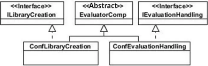
As shown in Figure 5, each component is represented by an abstract class. All its con-figurations correspond to concrete classes of the abstract class that represents it.
Fig. 5. Class diagram representing a component within the Spring framework.
The interface associated with a configuration of a component is represented by a Java interface as shown in the example below. Thus, each configuration implements its corresponding interface.
public interface IEvaluationHandling {
public void initEnv(HashMap<String, Object> penv);
public Object evalList(ArrayList<Object> listInstruction); }
Both interface method above come from two different classes. These are the classes of the objects involved in the configuration associated with the interface. This interface is implemented by the class that represents its configuration. The code below gives a brief description of such a class.
public class ConfEvaluationHandling extends EvaluatorComp implements IEvaluationHandling { //required interface
IErrorHandling required1; //Objects of the configuration Library lib;
InputOutout inOut;
// Constructor of component instances
public ConfEvaluationHandling(IErrorHandling req1){ //injection
required1=req1;
//creation of objects of component instances ObjectFactory();
}
//customized Factory for this configuration private void ObjectFactory(){
lib = new Library (this); inOut = new InputOutout (this); }
@Override
public void initEnv(HashMap<String, Object> penv) { lib.initEnv(penv);
} @Override
public Object evalList(ArrayList<Object> listeInstruction){ return lib.evalList(listInstruction);
} ... }
This class inherits from the abstract class representing the component. This is the way to associate a configuration to a component. The first attribute corresponds to the required interface. It will be injected via the constructor of the class using the configuration file (see below for an example). The two other attributes correspond to the objects that are directly involved in the configuration. The Factory method ObjectFactory creates the objects associated with the component instances. Note the ”this” given to construc-tors of the objects that allows them to know the component instance to which they are associated. Methods of the interface are implemented as redirections to the correspond-ing objects.
Below you have an excerpt of the configuration file for the Logo application in its component-based version.
<!-- Definition for EvaluatorComp-instance2 bean --> <bean id="EvaluatorConf2"
class= "com.irisa.evaluatorcomp.ConfEvaluationHandling"> <constructor-arg ref="ParserConf1"/> </bean>
<!-- Definition for ParserComp-instance1 bean --> <bean id="ParserConf1"
class="com.irisa.parsercomp.ConfErrorHandling"> <constructor-arg ref="GuiConf2"/> </bean> <!-- Definition for GuiComp-instance2 bean -->
<bean id="GuiConf2"
class="com.irisa.guicomp.ConfEventsHandling"> ...
</bean>
For the first created component instance (EvaluatorConf2) we can notice that the reference on the component instance (ParserConf1) is injected via the constructor of the component. This will be used for the required interface of the component instance (EvaluatorConf2).
The main statements in the launcher of the Logo application in its Sprint version are the follow:
IEventsHandling mainApp = (ConfEventHandling)
context.getBean("GuiConf2"); mainApp.main(args);
The first statement allows to retrieve an instance of the EventHandling component and to use it through its IEventsHandling interface. This component contains the class that holds the launcher (main method) of the Logo application, which is provided through the IEventsHandling interface. Thus, the second instruction starts the application.
To validate the component-based version of the Logo application, we replayed the 15 use cases, which were used to extract execution traces, and we got the same results. After that, we checked that the generated components can be used independently from each other. We reused the EvaluatorComp component in an application that allows to test the validity of Logo expressions through a command line. So we built a fairly simple component that allows to enter a Logo expression through the standard input. It requires the IEvaluationHandling interface of the EvaluatorComp compo-nent. It uses mainly the evalList method to submit the proposed expression. The returned result is translated into an understandable message and then printed on the standard output.
Obviously, we used an instance of ParserComp component that is required by the EvaluatorCompcomponent. Apart from this component instance, which is perfectly appropriate, the reuse of the component do not generate any problem.
6
Related Work
The reverse engineering research community has been actively investigating techniques to decompose (partition) the structure of software systems into subsystems (clusters or
component). In this section we target only work concerning the recovery of components in a legacy system.
6.1 Architecture Extraction
Software architecture plays an important role in at least six aspects of software devel-opment: understanding, reuse, construction, evolution, analysis and management [6]. Many approaches and techniques were proposed in the literature to support software architecture recovery [9,11,14,8,18,12,13], and often the problem is seen as a software clustering problem. The software clustering problem consists of finding a good partition of software modules based on various criteria, in particular, the dependencies among these modules [9]. Dependencies are extracted by static analysis, dynamic analysis, or using a combination of both (so-called hybrid approaches).
Among the approaches that use static analysis, Pourhaji Kazem et al. [11] proposed a genetic algorithm for clustering based on the weighted module dependency graph. Saeed et al. [14] used the Rigi tool to extract the function dependency graph and pre-sented a new clustering algorithm called the “combined” algorithm to implement soft-ware architecture recovery. Mancoridis et al. [8] extracted the file dependency graph from the source code and used a clustering algorithm based on a genetic algorithm.
With regard to approaches that use dynamic analysis, Yan et al. [18] described a technique that uses run time observations about an executing system to construct an ar-chitectural view of the system. In a previous work, we proposed an approach to restruc-ture an object-oriented application into a component-oriented one [2]. This approach is based on dynamic calls, i.e. actual calls at runtime with use cases, to determine the de-pendencies between classes. These dede-pendencies are then used by a genetic algorithm to derive groups of classes representing components.
For hybrid approaches, Richner et al. [12] presented an environment supporting the generation of tailorable views of object-oriented systems from both static and dynamic information. Claudio Riva et al. [13] proposed a technique for combining the analy-sis of static and dynamic architectural information to support the task of architecture reconstruction.
All these work achieve the starting point of the approach proposed in this paper (ie, sets of classes representing components). Thus, these work are complementary to our approach.
6.2 Component Instance Identification
In the field of Component-oriented programming (COP) , where the components are created from scratch (bottom-up approach) [4], a component instance is uniquely iden-tified with regard to the other instances, and is obtained from a component class (com-ponent descriptor), to enable use of the features associated with the com(com-ponent during the execution time. A variety of component-oriented languages have been proposed in the literature [4,3,5,19] to define components ( component classes andor component instances). These component languages are either dedicated to only software specifica-tion and are not executable (eg. UML 2.0 [7]) or dedicated as well as to transform
mod-els [4,15] into executable codes or to write programs by hand. SCL [4] is an example of the latter case, which defines the component by a descriptor that can be instantiated. Regarding the field of restructuring object-oriented systems into component-based systems, to the best of our knowledge, there is no work that identifies instances of extracted components.
7
Conclusion
The work presented in this paper aims to complete work on the extraction of compo-nents from legacy systems. Indeed, our approach allows to completely restructure an object-oriented application into a component-based application. Thus, it makes perma-nent mappings between elements from the extracted architecture and their correspond-ing ones in the code of the application. Identifycorrespond-ing the different instances of a com-ponent highlights its various aspects. Defining the interfaces of a comcom-ponent based on the various configurations of its instances is a way to make it reusable according to its different aspects.
Thus, we performed this work as a continuation of the work we have already done on the extraction of components from an object-oriented application [2]. Given the as-sumption we made (ie, the components are represented as a set of classes), the proposed approach also applies to all work on the extraction of components from object-oriented applications. However, our approach requires the existence of use cases in order to identify instances of components.
We have shown that instances of a component can be used to define its interfaces. We have already proposed an approach for the identification of interfaces of a com-ponent through a static analysis (on source code) of its dependencies on other compo-nents [16]. We used the same application as a case study (Logo) and we found some differences in the identified interfaces. In fact, static analysis takes into account objects that may be created but do not really exist in the context of the application (polymor-phism). On the other side, dynamic analysis allows to get objects related to classes dy-namically loaded. But the obtained interfaces are related to the context of the concerned application.
In one of our old work we presented an approach for component extraction that relies on a combination of static analysis (on source code) and dynamic analysis (calls between objects) [1]. This combination of the two approaches of analysis allowed to better cover aspects of extracted components. We think this may be the case with the definition of component interfaces. Thus, we expect in a future work the definition of component interfaces based on a combination of the two types of analysis in order to deduce dependencies between instances of components and getting more reusable components.
References
1. S. Allier, S. Sadou, H. Sahraoui, and R. Fleurquin. From object-oriented applications to component-oriented applications via component-oriented architecture. In 9th IEEE/IFIP Working International Conference on Software Architecture (WICSA), pages 214–223, Boul-der, Colorado, USA, june 2011. IEEE Computer Society.
2. Simon Allier, Houari A. Sahraoui, Salah Sadou, and St´ephane Vaucher. Restructuring object-oriented applications into component-object-oriented applications by using consistency with execu-tion traces. In CBSE, pages 216–231, 2010.
3. E. Bruneton, T. Coupaye, M. Leclercq, V. Qu´ema, and J-B. Stefani. An open component model and its support in Java. In CBSE, pages 7–22, 2004.
4. Luc Fabresse, Christophe Dony, and Marianne Huchard. Foundations of a simple and unified component-oriented language. Computer Languages, Systems & Structures, 34(2-3):130– 149, 2008.
5. Peter H. Fr¨ohlich, Andreas Gal, and Michael Franz. Supporting software composition at the programming language level. Sci. Comput. Program., 56:41–57, April 2005.
6. David Garlan. Software architecture: a roadmap. In Proceedings of the Conference on The Future of Software Engineering, ICSE ’00, pages 91–101, New York, NY, USA, 2000. ACM. 7. Object Management Group. Unified modeling language 2.1.2 super-structure specification.
Specification Version 2.1.2, Object Management Group, November 2007.
8. S. Mancoridis, B. S. Mitchell, and C. Rorres. Using automatic clustering to produce high-level system organizations of source code. In In Proc. 6th Intl. Workshop on Program Com-prehension, pages 45–53, 1998.
9. Faunes Martin, Marouane Kessentini, and Houari Sahraoui. Deriving high-level abstrac-tions from legacy software using example-driven clustering. In International Conference on Computer Science and Software Engineering, CASCON ’11, pages 188–199, 2011. 10. Nenad Medvidovic and Vladimir Jakobac. Using software evolution to focus architectural
recovery. Automated Software Eng., 13(2):225–256, 2006.
11. A.A. Pourhaji Kazem and S. Lotfi. An evolutionary approach for partitioning weighted module dependency graphs. In Innovations in Information Technology, 2007. IIT ’07. 4th International Conference on, pages 252 –256, nov. 2007.
12. Tamar Richner and Stphane Ducasse. Recovering high-level views of object-oriented appli-cations from static and dynamic information. In Proceedings ICSM99 (International Con-ference on Software Maintenance, pages 13–22. IEEE, 1999.
13. Claudio Riva and Jordi Vidal Rodriguez. Combining static and dynamic views for archi-tecture reconstruction. In Sixth European Conference onSoftware Maintenance and Reengi-neering (CSMR), pages 47–55. Nokia Research Center, 2002.
14. M. Saeed, O. Maqbool, H. A. Babri, S. Z. Hassan, and S. M. Sarwar. Software clustering techniques and the use of combined algorithm. In Proceedings of the Seventh European Con-ference on Software Maintenance and Reengineering, CSMR ’03, pages 301–, Washington, DC, USA, 2003. IEEE Computer Society.
15. Joo Costa Seco and Lus Caires. A basic model of typed components. In Elisa Bertino, editor, ECOOP, volume 1850 of Lecture Notes in Computer Science, pages 108–128. Springer, 2000.
16. A. Seriai, S. Sadou, H. Sahraoui, and S. Hamza. Deriving component interfaces after a restructuring of a legacy system. In 11th IEEE/IFIP Working International Conference on Software Architecture (WICSA), Sydney, Australia, April 2014. IEEE Computer Society. 17. Hironori Washizaki and Yoshiaki Fukazawa. A technique for automatic component
extrac-tion from object-oriented programs by refactoring. Sci. Comput. Program., 56(1-2):99–116, 2005.
18. Hong Yan, David Garlan, Bradley Schmerl, Jonathan Aldrich, and Rick Kazman. Discotect: A system for discovering architectures from running systems. International Conference on Software Engineering, pages 470–479, 2004.
19. Matthias Zenger. Keris: evolving software with extensible modules. Journal of Software Maintenance, 17(5):333–362, 2005.