Performance Simulation of a Solar-Driven Ejector Air
Conditioning System
Mokhtar Ghodbane
*1, Boussad Boumeddane
1, Abderrahmane Khechekhouche
21Saad DAHLAB University, Blida 1, Algeria
2Renewable Energy development unit in Arid Zones (UDERZR). El-Oued University, Algeria
Email*:[email protected]
Abstract— For proper comprehend the comportment and to
define the parameters of a solar-driven ejector air conditioning system at low or medium temperature; a dynamic model depends on the principles of conservation, the momentum mass and energy is developed. For this purpose, the thermodynamic characteristics of the liquid and vapor refrigerant were identified using the Engineering Equation Solver EES software. Linear Fresnel Reflector (LFR) has been used as a tool to convert solar energy into thermal energy. The water (R718) was used as a refrigerant. The performance of the ejector air conditioning system was compared as a function of the operating parameters of the subsystem. The thermal efficiency of the Fresnel linear concentrator was as high as 31.514 %, and the overall thermal performance of the machine (STR) was as high as 20.764 %. The results obtained during this study are very encouraging. This technique can be used for air conditioning in desert areas in southern Algeria, where fossil energy (petroleum, gas, etc.) is extracted and produced in various types.
Keywords— Thermal energy; Air conditioning system; Linear Fresnel solar Reflector, Ejector, Numerical simulation; Performance.
I. INTRODUCTION
The use of solar energy in sunny countries such as Algeria is an effective way to overcome energy shortages, especially in rural areas where it is sometimes difficult and expensive to provide them with a traditional electricity grid [1-10]. In addition, Algeria is a country where the solar potential is very important; the annual sunshine is always greater than 2×10⁴ kJ/m² of catchment area. Therefore, it is important to exploit this natural resource in the field of cold production especially in the a solar-driven ejector air conditioning system because of its simplicity of design and implementation.
Due to the increasing cost of energy and the reduction of its sources, a solar-driven ejector air conditioning system using low or medium temperature heat rejection or a free energy source (solar) have become in recent years an interesting subject of study [11-19].
Among the machines that are currently used in the field of air conditioning, the a solar-driven ejector air conditioning machine on the one hand, because of the cold needs in buildings that exist in industrial fields (oil complexes, etc.) and
the availability of thermal resources either of solar origin in developing countries, or from low-temperature thermal discharges in industrialized countries, and secondly, thermodynamicists encourage the study of refrigeration production systems directly using solar energy. thermal energy [11-18]. The means by which this operation is carried out is the use of ejector refrigeration machines, also called thermodynamic machines with three temperature sources in which:
The hot source can be powered by the solar energy or by heat discharges;
The cold source is produced at the cold source, i.e. the evaporator;
The residual heat from the condenser transferred to the ambient medium constitutes the third source.
In this scientific article, we will discuss the details of using a solar-driven ejector air conditioning machine. The location chosen for the study is El-Oued region, Algeria. The solar collector chosen as a Solar Conversion Tool is Linear Fresnel Reflector (LFR). All the thermodynamic properties of the air conditioning system will be determined based on the energy equilibrium equations that govern this system.
II. GOVERNING EQUATIONS OF THE AIR CONDITIONING SYSTEM
A. Ejector air conditioning subsystem
In this section, a description of the operating principles of the ejector solar air conditioning machine is presented. The operating mode of this air conditioning system is presented in the form of equations using the laws of thermodynamics and momentum conservation, mass conservation and energy, to determine the performance characteristics. The refrigerant "water" plays a key role in improving the performance of a solar ejector air conditioning system.
The ejector solar air conditioner is a very effective solution in rural areas and in desert industrial complexes because it has simple assembly and it has an acceptable performance [12, 13, 18-24]. For these reasons, we find that this air conditioning
technology is more attractive than conventional compression technology because it is less expensive.
Fig. 1. Illustrative schematization of a typical ejector [25].
Generally, the model of the ejector air conditioning subsystem is based on the thermodynamic states in each operating point.
a)
b)
Fig. 2. Operating cycle of an ejector air conditioner [26, 27].
The ejector air-conditioning subsystem as illustrated in Figure (2), it has two closed cycles :
The driving loop (7-1-2-3-4-5-6-7); The refrigerating loop (7-8-9-5-6-7). 1) The driving loop (DL)
In the power cycle, the energy supplied to the generator is used to evaporate a portion of the refrigerant which represents the driving fluid (primary), which is at high pressure (from state 1 to state 4), then passes through the ejector where it is mixed with the other part of the refrigerant which represents the fluid entrained (secondary), coming from the evaporator and where also performs a pressure recovery (from state 4 to state 6). Then all of the refrigerant passes through the condenser where it is condensed to the liquid state (from state 6 to state 7). This liquid will be pumped (pressure increase) to the generator and thus completes the cycle (from state 7 to state 1).
2) The cooling loop (CL)
In the refrigeration cycle, part of the refrigerant in the liquid state which represents the entrained fluid (secondary) passes through an expansion valve to bring it to a state of low pressure (from state 7 to state 8). The refrigerant subsequently enters the evaporator where it produces by evaporating the desired cold (from state 8 to state 9). The refrigerant is mixed with the other part (the driving fluid) in the ejector where it is compressed (from state 9 to state 6) and the mixture passes through the condenser where it is condensed to the liquid state and complete thus the cycle (from state 6 to state 7).
These two Loops (DL and CL) illustrate the thermodynamic working principle of the ejector air conditioner.
In order for the ejector cycle to function well, this pressing condition (PC = critical pressure) must be achieved. The pressure at the ejector outlet (P6) is less than the critical pressure of the condenser (P6 ≤ PC). in this study, a constant pressure mixing ejector (CPM Ejector) has been used, where its outlet from the nozzle is in the suction chamber before the fixed chamber, the primary and secondary flows are mixed in the chamber Aspiration at this pressure The pressure of the mixing streams remains constant along the chamber from the outlet of the nozzle to the inlet of the constant surface section. This kind of ejector has better efficiency than the rest of the ejector.
For optimal understanding of the principle of ejector work, it is advisable to familiarize yourself with the gas-dynamic lessons and a good understanding of the working principle of convergent-divergent pipes [27-30].
According to Figure (2), the energy balance at the mixing point inside the ejector can be written as [27-29] :
9 e 3 g 5 e g
m
)h
m
.h
m
.h
(m
(1)The isentropic efficiency of the ejector nozzle is defined as [27-29] : is 4, 3 4 3 N
h
h
h
h
η
(2)The isentropic efficiency of the Diffuser is given by [27-29] : 5 6 5 is 6, D
h
h
h
h
η
(3)The mass ratio (drive ratio) is given by [26-29]:
1
h
h
h
h
)
.η
(η
m
m
ω
5 is 6, is 4, 3 D N g e
(4)The isentropic ejector efficiency is given by the following relation [27-29] :
D N
.η
η
λ
(5)The compression ratio is defined as following [26-29]:
e c p
P
P
r
(6)The ejector air conditioning subsystem performance is defined as the ratio between the cooling capacity “Qe (W)” and the required heat input “Qg (W)” to the ejector [26-29, 31] :
)
(
)
(
1 3 8 9h
h
m
h
h
m
Q
Q
COP
g e g e ejc
(7)We recall that: “h (J/kg)” refers to the Enthalpy, “mg (Kg/s)” is the mass flow rate of the refrigerant in the generator, [Kg.s-1] and “me (Kg/s)” is the mass flow of the refrigerant in the evaporator.
The thermodynamic analysis of the two loops of the ejector air conditioning subsystem was performed by the Engineering Equation Solver (EES).
B. Linear Fresnel Reflector subsystem
We know that the cost of operating renewable energies is very high at the moment, so the production costs and the efficiency of the product must be agreed in order to have an efficient device with an acceptable price. For the solar system with parabolic trough solar collector (PTC), the cost of designing the PTC solar concentrator is very high because it relies on the shaping of the glass to obtain the parabolic form of the reflecting mirror [5, 7, 27-29, 32-36], so the use of flat reflector mirrors will significantly reduce the cost of manufacturing linear solar concentrators [10]. For this reason, much of the scientific research has been directed towards the development the solar system with the Linear Fresnel Reflector (LFR), where many countries such as Spain and Germany have widely exploited this technology of acceptable price with a low efficiency [6, 28, 37].
The operating principle of a Linear Fresnel Reflector (LFR) lies in its flat mirrors, where each of these mirrors can be rotated following the path of the sun to constantly redirect and focus the direct sunlight « DNI, (W/m²) » towards an absorber tube [10]. A heat transfer fluid is heated by circulating in this horizontal tube [6, 30, 38].
Fig. 3. Schematic and view of Fresnel solar power plants [39].
In this part, we will determine the global heat loss coefficient « UL, (W/m².K) » of the absorber tube to be able to determine the temperatures of the heat transfer fluid at the exit of the absorber tube and the other thermal parameters.
Fig. 4. The energy balance at the absorber tube.
Table (1) shows the geometric parameters of the collector, and Table (2) shows the optical characteristics of the solar concentrator studied.
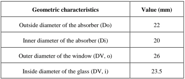
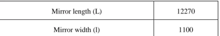
TABLE I. GEOMETRICAL PARAMETERS OF THE LFR CONCENTRATOR.
Geometric characteristics Value (mm)
Outside diameter of the absorber (Do) 22 Inner diameter of the absorber (Di) 20 Outer diameter of the window (DV, o) 26 Inside diameter of the glass (DV, i) 23.5
Mirror length (L) 12270
Mirror width (l) 1100
We will thermally analyze by a numerical tool the LFR concentrator in order to estimate the variation of the temperature of the heat transfer fluid (HTF) at the exit of the absorber tube as a function of the direct solar radiation (DNI) for the El-Oued site "Oued Souf" (altitude 61 meters, latitude 33.51 ° N and longitude 6.78 ° E), Algeria.
TABLE II. OPTICAL PARAMETERS OF THE LFR COLLECTOR.
Parameters Value
Overall average optical error 03 mrad Mirror reflection coefficient (ρm) 0.85 Transmissivity of the glass tube () 0.945 Absorber absorption coefficient (α) 0.8 Emissivity of the absorber tube (A) 0.12
Emissivity of the glass tube (V) 0.935
Heat exchange occurs between the coolant, the absorber and the glass. A calculation program in Engineering Equation Solver (EES) has been developed to make the necessary calculations, for this, we admit the following hypotheses:
The heat transfer fluid is incompressible;
The ambient temperature around the concentrator is uniform;
The effect of the shadow of the absorber tube on the mirror is negligible;
The solar flux at the absorber is evenly distributed; The glass is considered opaque to infrared radiation; The conduction exchanges in the absorber tube and the
glass tube are negligible.
The heat flux “qgain, (W)” transmitted to the fluid is given by the following relation [2, 36]:
op a L r i amb
r
gain
F
η
DNI
A
U
A
T
T
q
(8)With "DNI, (W/m²)" is the direct solar radiation, "Aa, (m²)" is the opening area of the collector, "Ar, (m²)" is the absorber tube surface, "Ti, (K) "is the fluid inlet temperature," Tamb, (K) "is the ambient air temperature and Fr is the heat dissipation factor.
The optical efficiency (ηopt) of the concentrating LFR can be expressed by [37, 40]:
)
(H
)sin
(
cos
1
γ
m
ρ
α
0.7
opt
η
2δ
2 S (9)With the factor "" is the interception factor, "δ, (°)" is the declination angle and "HS, (°)" is the altitude of the sun.
The overall heat loss coefficient "UL, (W / m².K)" is given as follows [2, 27, 36] :
1 a r r, v a c r, w r Lh
1
A
h
h
A
U
(10)With "Av, (m²)" is the area of the glass, "hw, (W/m².K)" is the convective heat exchange coefficient between the glass and the ambient air, "hr,ca, (W /m².K)" is the radiative exchange coefficient between the glass and the ambient air and "hr,ra, (W/m².K)" is the radiative exchange coefficient between the absorber and the glass.
To calculate the temperature of the coolant at the exit of the absorber tube, we can use the following equation [27, 36, 41]:
p . i o
C
T
T
m
q
gain
(11)The thermal efficiency of the LFR solar concentrator can be calculated by the equation :
a gain th
A
DNI
q
η
(12)The thermal modeling of the LFR solar concentrator has been done by a procedure of calculation and programming by EES. For that, we have elaborated a computation program to simulate the useful power (qgain), the global coefficient of the heat losses (UL), the optical efficiency (ηopt) of the LFR solar collector, the fluid temperature (To) at the outlet of the absorber and the thermal efficiency of the LFR solar reflector.
III. DYNAMIC STUDY OF THE EJECTOR SOLAR AIR CONDITIONING SYSTEM
An ejector solar air conditioning machine is a system that has three sources of heat (a hot source corresponding to the motive heat supplied to the system, a cold source corresponding to that of the production of cold and a warm source that makes a connection between both sources). The ejector solar air conditioner is similar to the conventional compression air conditioning system except that a pump, a steam generator and an ejector replace the compressor.
The direct solar radiation (DNI) transformed by the linear Fresnel concentrator (LFR) into thermal energy is used to generate in the generator the high temperature and high pressure steam (primary fluid) which expands in the primary nozzle of the ejector. At the outlet, the high speed primary fluid drives the secondary fluid from the evaporator. Then, the primary and secondary streams mix at constant pressure in the mixing chamber. A first pressure increase due to the formation of a shock wave takes place in the mixing chamber followed by a second due to compression in the Diffuser. At the outlet of the Diffuser, the mixture condenses in a condenser. Part of the condensate passes into the evaporator through a throttle valve
to produce the cooling effect while the rest of the liquid returns to the generator via a circulation pump.
Fig. 5. Solar ejector air conditioning system for balance analysis [27].
For the performance of the ejector solar air conditioning machine, it can be introduced as the product of the ejector air conditioning subsystem performance (COPejc) and the used solar concentrator efficiency (ηth). Therefore, the following relation gives the solar thermal ratio (STR) relation of the system [26, 27, 31]:
th ejc
COP
STR
.
(13)The air conditioning system studied in this paper can provide a cooling load of 12000 W. The main purpose of this study is to determine the parameters that are affected on the various performance of the ejector solar air conditioning system. In this paper, the thermal model of the Fresnel solar concentrator is without storage tank and without auxiliary boiler. The simulation is executed under the following assumptions:
The working fluid is considered a perfect fluid with constant thermophysical parameters ;
The kinetic energy of primary and secondary flows is negligible ;
The flow is stationary ;
The internal walls of the ejector are adiabatic ; The outlet of the ejector is connected to the condenser. To calculate direct solar radiation (DNI) from sunrise to sunset, an algorithm has been developed to simulate direct
solar radiation by the semi-empirical model of PERRIN DE BRICHAMBAUT [6, 30, 42], where the June 11, 2018 was selected as the day of the study. Table (3) translate the operating conditions of the ejector air conditioning subsystem. TABLE III. SERVICE OPERATING CONDITIONS OF THE EJECTOR SOLAR AIR
CONDITIONING MACHINE.
Service operating conditions Value (°C)
Generator temperature (Tb) 110
Condenser temperature (Tc) 35
Evaporator temperature (Te) 05
Generally in El-Oued region, the climate is desert. There is virtually no rainfall all year long in El Oued, where the average annual rainfall is 74 mm, resulting in a virtually dry atmosphere throughout the year. In addition, the hottest month of the year is July, but the coldest month is January, where the difference in air temperature between the lowest and the highest is equal to 22.6 ° C throughout the year. Figure (6) clearly illustrates the changes of direct solar radiation on June 11, 2018. 5 6 7 8 9 10 11 12 13 14 15 16 17 18 19 0 100 200 300 400 500 600 700 800 900 1000 1100 DNI (W/m²)
TIME (Hour)
Fig. 6. Changes of direct solar radiation on June 11, 2018.As shown in Figure (6), the maximum value of direct solar radiation has peaked at midday, with a value equal to 1021.84617 (W/m²). Generally, the average solar radiation change for the studied day has exceeded 8 956.72322 (W/m²). These values for solar radiation are very significant and can be exploited to operate an air conditioning system; it can also be used in many other technological fields such as electricity generation, desalination, etc.
The solar thermal concentrator of Fresnel is a device designed to collect solar energy transmitted by direct solar radiation and communicate it to a coolant (gas or liquid) in the form of heat. This heat energy can then be used in various industrial processes. The nature of heat transfer fluids is one of the most important factors affecting the efficiency of the associated work system. A heat transfer fluid (HTF) is a fluid that transports heat between two or more temperature sources. These fluids are used in thermal engine cooling systems such as car engines, refrigerators, air conditioners, solar thermal
collectors, electronic circuit radiators, coal, oil, gas or nuclear power plants. Each heat transfer fluid is chosen according to its physical and chemical properties and cost: viscosity, volume heat capacity, latent heat of vaporization (or liquefaction) in case of phase change, electrical conductivity, oxidizing properties, etc. In this study, water has been adopted as heat transfer fluid. Figure (7) shows changes in the temperature of the absorber tube “TAb, (K)”, the heat transfer fluid “TF, (K)” and the glass tube “TV, (K)”.
5 6 7 8 9 10 11 12 13 14 15 16 17 18 19 310 320 330 340 350 360 370 380 390 400 410 420 430 440 450 460 TEMPERATURES (K) TIME (Hour) Absorber tube temperature Fluid temperature Glass tube temperature
Fig. 7. Variations of temperature on July June 11, 2018.
Through the previous figure, it was observed that the temperature of the heat transfer fluid (HTF) has reached 444.90685 (K), which indicates that the water has changed from its liquid state to the vapor state. The absorber tube temperature has reached 451.49101 (K) and the glass cover temperature has reached 414.75504 (K). It should be noted that the climatic factors have a direct impact on the amount of heat obtained by the heat transfer fluid from the absorber tube.
The convective and radiative exchange losses to the outside air are very important, in order to limit them, a glass envelope covers the absorber tube and makes it possible, by evacuating the annular space, to eliminate thermal losses by convection between the absorber tube and the glass envelope. In addition, the heat losses can be reduced also by reducing the emissivity in the infrared of the absorber tube using the selective surfaces. These surfaces are dark in color to absorb the maximum amount of solar radiation by emitting very little infrared. In this study, the absorbent tube is a copper tube surrounded by a glass tube. With regard to air temperature, it influences the coefficient of heat loss by convection outdoors, because the physical properties of exterior air vary according to the ambient temperature. Therefore, a small emissivity of the absorber tube and the vacuum in the annular space between the absorber tube and the glass envelope can reduce heat losses. It can be said that the internal thermal radiation losses decrease with the reduction of the absorber tube emissivity and the convective losses decrease with the creation of the vacuum in the annular space. The next figure shows the changes in the
total loss coefficient “UL, (W/m².K)” in the heat of the absorber tube. 27 54 81 108 135 3.50 3.75 4.00 4.25 4.50 4.75 5.00 5.25 5.50 5.75 6.00 Ove rall c oef fici ent of t hermal l oss (W/m².K) [TAb-Tamb] (K) Fig. 8. Variation of the overall coefficient of thermal losses.
Generally, the efficiency measurement of the linear Fresnel concentrator is the ratio between the thermal power that it provides to the heat transfer fluid and the power of the direct solar radiation which arrives on the useful surface of this collector. The power supplied is the power converted to heat in the solar concentrator, minus the losses. The thermal losses are the infrared radiation returned to the outside and the heat dissipated to the outside. As shown in Figure (8), the change in the total thermal loss coefficient “UL, (W/m².K)” is an almost linear function that increases with the increasing temperature difference between the absorber tube and the surrounding atmosphere. The geometric dimensions of the solar collector and the climatic conditions of the area in which it is located directly affect this coefficient.
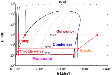
Figure (9) shows the thermodynamic loops of the solar air conditioner that depends on the ejector. Remember, water is used as coolant. 0.0x100 1.0x10⁶ 2.0x10⁶ 3.0x10⁶ 4.0x10⁶ 102 103 104 105 106 107 108 h [J/kg] P [P a ] 110°C 35°C 05°C 0.2 0.4 0.6 0.8 R718 Generator Condenser Evaporator Ejector Pump Throttle valve
The following table shows the dimensions of primary nozzle throat diameter (Dt) and constant area section diameter (Dm) which is characterized by the ejector under critical conditions (P4 ≤ Pc, where Pc = 4757 Pascal) with the previous operating conditions (see TABLE III. ) and with a load cold equal to 12000 W.
TABLE IV. DIMENSIONS OF (Dt) AND (Dm) UNDER CRITICAL CONDITIONS.
Ejector critical condition (P4≤ Pc=
4757 Pascal)
Primary nozzle throat
diameter (Dt) 0.005888 m Constant area section
diameter (Dm) 0.04388 m
Table (5) shows the value of the drive ratio (ω) and the performance value of the ejector air conditioning subsystem with a cooling load (Qe) equal to 12000 W.
TABLE V. THE DRIVE RATIO (Ω) AND THE PERFORMANCE OF THE EJECTOR COOLING SUBSYSTEM WITH A COOLING LOAD OF 12000W.
Ejector critical condition (P4≤ Pc=
4757 Pascal)
ω 0.4933
COPejc 0.658875
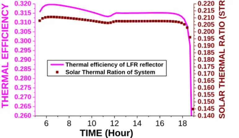
Figure (10) shows the evolution of the solar thermal ratio (STR) of air conditioning system in critical mode, and thermal efficiency curve changes of the LFR concentrator as a function of time during the day of June 11, 2018.
6 8 10 12 14 16 18 0.260 0.265 0.270 0.275 0.280 0.285 0.290 0.295 0.300 0.305 0.310 0.315 0.320
Thermal efficiency of LFR reflector Solar Thermal Ration of System
TIME (Hour) THERMAL EFF ICIENCY 0.140 0.145 0.150 0.155 0.160 0.165 0.170 0.175 0.180 0.185 0.190 0.195 0.200 0.205 0.210 0.215 0.220 SO LAR THER MAL RA TIO ( STR )
Fig. 10. Variation in machine performance and change in thermal efficiency of solar concentrator.
From Figure (10), it is very remarkable that the STR varies automatically according to the temperatures (Te), (Tc) and (Tb) of the ejector air conditioning subsystem, and is affected by the change of the thermal efficiency of the Fresnel solar collector. It seems clear as well as the efficiency of the machine is about 19%. It can be said that this performance value (STR) is
generally acceptable since the thermal efficiency (ηth) of the Linear Fresnel solar concentrator does not exceed 32%, except in very special cases [6, 37].
The application of this type of air conditioner shows that the STR is very sensitive to changes of the condenser temperature (Tc), where the high temperature of the condenser reduces the efficiency of the air conditioner with the ejector. The increasing the temperature of generator (Tb) and evaporator (Te) increases the efficiency of the system.
IV. CONCLUSION
The work that we have presented in this paper has allowed us to acquire very important knowledge about ejector solar air conditioning machines.
According to this study, the performance of the air conditioning subsystem (COPejc) is very sensitive to changes in condenser temperature (Tc), so to increase the performance of the machine it is necessary to increase the temperatures of the hot sources (Tg and Te). On the other hand, it is found that the Fresnel linear concentrator is effective to operate this machine, even if it has a low thermal efficiency.
In this study, the thermal efficiency of the concentrates reached 31.514 %, while the overall the solar thermal ratio (STR) of air conditioning system in critical mode was 20.764 %.
Finally, this technique can be exploited in the Algerian desert, where the fossil energies are extracted and exploited. This technology will reduce the consumption of electricity in these institutions in large proportions.
In the future, we will try to experiment with this system, and we will work to improve the operational conditions of this type of systems.
V. REFERENCES
[1] J. Wang, J. Wang, X. Bi, and X. W, "Performance simulation comparison for parabolic trough solar collectors in China," International Journal of Photoenergy, vol. 2016, Article ID 9260943, pp. 1-16, http://dx.doi.org/10.1155/2016/9260943, 2016. [2] S. A. Kalogirou, Solar Energy Engineering :
Processes and Systems, 1st ed. Academic Press, 2009.
[3] S. M. Jeter, "Analytical determination of the optical performance of practical parabolic trough collectors from design data," Solar Energy, vol. 39, no. 1, pp.
11-21,
https://doi.org/10.1016/S0038-092X(87)80047-6, 1987.
[4] V. K. Jebasingh and G. M. J. Herbert, "A review of solar parabolic trough collector," Renewable and Sustainable Energy Reviews, vol. 54, pp. 1085–1091, http://dx.doi.org/10.1016/j.rser.2015.10.043, 2016. [5] M. Ghodbane, B. Boumeddane, and N. Said, "A
linear Fresnel reflector as a solar system for heating water: theoretical and experimental study," Case
Studies in Thermal Engineering, vol. 8, no. C, pp. 176-186,
http://dx.doi.org/10.1016/j.csite.2016.06.006, 2016. [6] M. Ghodbane and B. Boumeddane, "Estimating solar
radiation according to semi empirical approach of PERRIN DE BRICHAMBAUT: application on several areas with different climate in Algeria," International Journal of Energetica, vol. 1, no. 1, pp. 20-29, 2016.
[7] M. Ghodbane and B. boumeddane, "Engineering design and optical investigation of a concentrating collector: Case study of a parabolic trough concentrator " J. Fundam. Appl. Sci., vol. 10, no. 2, pp. 148-171, 2018.
[8] A. Fernandez-Garcıa, E. Zarza, L. Valenzuela, and M. Perez, "Parabolic-trough solar collectors and their applications," Renewable and Sustainable Energy
Reviews, vol. 14, pp. 1695–1721,
https://doi.org/10.1016/j.rser.2010.03.012, 2010. [9] J. A. Duffie and W. A. Beckman, Solar Engineering
of Thermal Processes, 4th ed. Wiley, 2013.
[10] M. Ghodbane, B. Boumeddane, Z. Said, and E. Bellos, "A numerical simulation of a linear Fresnel solar reflector directed to produce steam for the power plant," Journal of Cleaner Production, vol.
231, pp. 494-508.
https://doi.org/10.1016/j.jclepro.2019.05.201, 2019. [11] C. Vereda, R. Ventas, A. Lecuona, and M. Venegas,
"Study of an ejector-absorption refrigeration cycle with an adaptable ejector nozzle for different working conditions," Applied Energy, doi: 10.1016/j.apenergy.2011.12.070 no. 0.
[12] W. Zhang, X. Ma, S. A. Omer, and S. B. Riffat, "Optimum selection of solar collectors for a solar-driven ejector air conditioning system by experimental and simulation study," Energy
Conversion and Management, doi:
10.1016/j.enconman.2012.02.026 no. 0.
[13] B. M. Diaconu, "Energy analysis of a solar-assisted ejector cycle air conditioning system with low temperature thermal energy storage," Renewable Energy, doi: 10.1016/j.renene.2011.06.031 vol. 37, no. 1, pp. 266-276, 2012/1// 2012.
[14] G. Grazzini, A. Milazzo, and D. Paganini, "Design of an ejector cycle refrigeration system," Energy
Conversion and Management, doi:
10.1016/j.enconman.2011.09.015 vol. 54, no. 1, pp. 38-46, 2012/2// 2012.
[15] T. Jaruwongwittaya and G. Chen, "Application of Two Stage Ejector Cooling System in a Bus," Energy Procedia
2011 2nd International Conference on Advances in Energy
Engineering (ICAEE), doi:
10.1016/j.egypro.2011.12.916 vol. 14, no. 0, pp. 187-197, 2012/// 2012.
[16] R. K. McGovern, G. Prakash Narayan, and J. H. Lienhard V, "Analysis of reversible ejectors and
definition of an ejector efficiency," International Journal of Thermal Sciences, doi: 10.1016/j.ijthermalsci.2011.11.003 vol. 54, no. 0, pp. 153-166, 2012/4// 2012.
[17] A. Sözena, T. Menlika, and E. Özbaşb, "The effect of ejector on the performance of diffusion absorption refrigeration systems: An experimental study,"
Applied Thermal Engineering, doi:
10.1016/j.applthermaleng.2011.09.009 vol. 33-34,
no. 0, pp. 44-53.
https://doi.org/10.1016/j.applthermaleng.2011.09.009 , 2012/2// 2012.
[18] J. Yan, W. Cai, and Y. Li, "Geometry parameters effect for air-cooled ejector cooling systems with R134a refrigerant," Renewable Energy, doi: 10.1016/j.renene.2012.03.031 vol. 46, no. 0, pp. 155-163, 2012/10// 2012.
[19] M. Ghodbane, B. Boumeddane, and A. k. Hussein, "Performance analysis of a solar-driven ejector air conditioning system under El-Oued climatic conditions, Algeria " Journal of Thermal Engineering, 2019.
[20] M. Mohanraj, S. Jayaraj, and C. Muraleedharan, "Applications of artificial neural networks for refrigeration, air-conditioning and heat pump systems—A review," Renewable and Sustainable Energy Reviews, doi: 10.1016/j.rser.2011.10.015 vol. 16, no. 2, pp. 1340-1358, 2012/2// 2012.
[21] Y. Jia and C. Wenjian, "Area ratio effects to the performance of air-cooled ejector refrigeration cycle with R134a refrigerant," Energy Conversion and Management, doi: 10.1016/j.enconman.2011.09.002 vol. 53, no. 1, pp. 240-246, 2012/1// 2012.
[22] X.-W. Li and X.-S. Zhang, "Membrane air-conditioning system driven by renewable energy," Energy Conversion and Management, doi: 10.1016/j.enconman.2011.08.001 vol. 53, no. 1, pp. 189-195, 2012/1// 2012.
[23] B. Zhang, X. Song, J. Lv, and J. Zuo, "Study on the key ejector structures of the waste heat-driven ejector air conditioning system with R236fa as working fluid," Energy and Buildings, doi: 10.1016/j.enbuild.2012.02.009 no. 0.
[24] D. L. Loveday, "Thermal performance of air-heating solar collectors with thick, poorly conducting absorber plates," Solar Energy, doi: 10.1016/0038-092X(88)90062-X vol. 41, no. 6, pp. 593-602, 1988/// 1988.
[25] S. Varga, P. M. S. Lebre, and A. C. Oliveira, "CFD study of a variable area ratio ejector using R600a and
R152a refrigerants.
http://dx.doi.org/10.1016/j.ijrefrig.2012.10.016," International journal of refrigeration vol. 36, pp. 157-165, 2013.
[26] W. Pridasawas and P. Lundqvist, "A year-round dynamic simulation of a solar-driven ejector refrigeration system with iso-butane as a refrigerant,"
International Journal of Refrigeration, vol. 30, p. 840e850, 2007.
[27] M. Ghodbane and B. Boumeddane, "Numerical simulation of a solar-driven ejector refrigeration cycle coupled to a parabolic trough concentrator," International Journal of Chemical and Petroleum Sciences, vol. 5, no. 1, pp. 1-12, 2016.
[28] M. Ghodbane, "Étude et optimisation des performances d'une machine de climatisation a éjecteur reliée à un concentrateur solaire " Doctorat en système énergétiques et thermiques, Département de Mécanique Université Saad Dahleb de Blida 1 2017.
[29] M. Ghodbane, B. Boumeddane, S. Largot, and H. Berkane, "Modélisation d'un cycle de réfrigération solaire à éjecteur couplée à un concentrateur cylindro-parabolique," in International Conférence en Clean Cooling Technologies in the ME NA Regions (ICT3_MENA'2015) Bou Smail, W. Tipaza, 5-6 October 2015.
[30] M. Ghodbane and B. Boumeddane, "Physical description of an isentropic flow in a Laval nozzle. https://www.cder.dz/download/Art19-1_5.pdf," Revue des Energies Renouvelables, vol. 19, no. 1, pp. 41-47, 2016.
[31] W. Pridasawas and P. Lundqvist, "An exergy analysis of a solar-driven ejector refrigeration system," Solar Energy, vol. 76, pp. 369–379, 2004. [32] M. Ghodbane and B. Boumeddane, "Numerical
modeling of a parabolic trough solar collector at bouzaréah, Algeria," International Journal of Chemical and Petroleum Sciences, vol. 4, no. 2, pp. 11-25, 2015.
[33] M. Ghodbane and B. Boumeddane, "Optical modeling and thermal behavior of a parabolic through solar collector in the algerian sahara " AMSE JOURNALS-AMSE IIETA publication-2017-Series: Modelling B, vol. 86, no. 2, pp. 406-426, 2017. [34] M. Ghodbane and B. Boumeddane, "A parabolic
trough solar collector as a solar system for heating water: a study based on numerical simulation " International Journal of Energetica (IJECA) vol. 2, no. 2, pp. 29-37 2017.
[35] M. Ghodbane, B. Boumeddane, and S. Largot, "Etude optique et thermique d’un concentrateur cylindro-parabolique en site d’Alger, Algerie," in IXth International Congress on Renewable Energy and the Environment, Djerba, Tunisie, 18-20 March 2015.
[36] M. Ghodbane, B. Boumeddane, and S. Largot, "Simulation Numérique d’un Concentrateur Cylindro-Parabolique en El Oued, Algérie," International Journal of Scientific Research & Engineering Technology (IJSET), vol. 3, no. 2, pp. 68-74, 2015.
[37] M. Ghodbane, B. Boumeddane, and N. Said, "A linear Fresnel reflector as a solar system for heating water: theoretical and experimental study," Case Studies in Thermal Engineering, vol. 8, no. C, pp. 176-186. https://doi.org/10.1016/j.csite.2016.06.006, 2016.
[38] R. Abbas, M. J. Montes, M. Piera, and J. M. Martinez-Val, "Solar radiation concentration features in Linear Fresnel Reflector arrays," Energy
Conversion and Management, doi:
10.1016/j.enconman.2011.10.010 vol. 54, no. 1, pp. 133-144, 2012/2// 2012.
[39] B. nature. (2018). Les centrales à capteurs linéaires de Fresnel, Web page: http://3.bp.blogspot.com/-CCAzBW8D5us/VivJN8cVdMI/AAAAAAAADX4/uF0 KvqHv_44/s1600/3.JPG.
[40] K. F. Yogi D.G, Kreider J.F, " Off-Normal Incidence Effects," in Principles of solar engineering, T. Francis., Ed. 2nd Edition ed., 1999, p. 139.
[41] M. Li and L. L. Wang, "Investigation of evacuated tube heated by solar trough concentrating system. http://dx.doi.org/10.1016/j.enconman.2006.03.003," Energy Conversion and Management, vol. 47, pp. 3591–3601, 2006.
[42] M. Ghodbane, B. Boumeddane, and S. Largot, "Développement d'un programme informatique pour la simulation du rayonnement solaire reçu par une surface inclinée," in Journée d'étude sur les énergies renouvelables et leurs applications, Université d'El Oued, Avril 2015.
![Fig. 2. Operating cycle of an ejector air conditioner [26, 27].](https://thumb-eu.123doks.com/thumbv2/123doknet/12169342.313435/2.918.74.446.413.993/fig-operating-cycle-ejector-air-conditioner.webp)
![Fig. 5. Solar ejector air conditioning system for balance analysis [27].](https://thumb-eu.123doks.com/thumbv2/123doknet/12169342.313435/5.918.72.448.123.502/fig-solar-ejector-air-conditioning-balance-analysis.webp)