Paper ID: 136, Page 1
TESTING AND MODELING A VANE EXPANDER USED IN AN ORC
WORKING WITH HEXAMETHYLDISILOXANE (MM)
Vaclav Vodicka1*, Ludovic Guillaume2, Jakub Mascuch3 and Vincent Lemort4 1, 3
University Centre for Energy Efficient Buildings Czech Technical University in Prague
Trinecka 1024, 273 43 Bustehrad Czech Republic 1 e-mail: [email protected] 3 e-mail: [email protected] 2, 4 Thermodynamics Laboratory University of Liège
Campus du Sart Tilman, B49, 4000 Liège Belgium 2 e-mail: [email protected] 4 e-mail: [email protected] * Corresponding Author
ABSTRACT
Waste heat from industrial production carries considerable potential for further use. Organic Rankine Cycle (ORC) brings a possibility to produce electrical energy from heat, originally intended to be released to the surroundings. For ORC systems with power output up to 10 kW, small-scale turbines are still expensive to manufacture and their use can be problematic in terms of high shaft speed or quality of inlet vapor. It is therefore preferable to use positive displacement expanders. The first part of this paper presents and analyses the measurements conducted on a prototype of vane expander. This vane expander characterized by a 1 kW power output operates in an ORC heat engine that uses hexamethyldisiloxane as a working fluid. The expander inlet temperature varies approximately from 135 °C to 150 °C, inlet pressure varies approximately from 200 to 300 kPa abs, isentropic efficiency from 0.4 to 0.58. The second part of the paper proposes a grey-box model, which is calibrated on the base of the measured data. This lumped-parameter model takes into consideration major losses of the expander: supply and discharge pressure losses, under and over-expansion, internal leakages and mechanical losses. The model is finally used to assess the impact of each source of losses on the overall performance of the expander.
1. INTRODUCTION
ORC technology seems to be a promising solution for waste heat recovery (WHR) and combined heat and power (CHP) generation especially in a small scale (up to 10 kWel). Waste heat can be recovered from many industrial processes or combustion engines; small scale CHP units for households and small businesses fit into the concept of smart grids. Rising amount of publications focused on devices with low power output shows strong importance of this topic. According to Qiu et al. (2011) the use of positive displacement expanders especially scroll or vane type is a good choice for low power ORC applications because of their low cost and good efficiency over a wide range of operating conditions. One of the most noticeable advantages of positive displacement expanders is insensitivity on a quality of admission vapor compared to turbine technology. This allows a simplification of design of a cycle and its controlling algorithms. Only a few recently published papers (e.g. Cipollone, 2014, Xia, 2013,
Paper ID: 136, Page 2
Yang, 2008) present experimental measurement and evaluation of sliding vane expanders. This paper presents an experimental characteristics of a sliding vane expander used in an ORC operating with hexamethyldisiloxane (MM) as a working fluid. This ORC was built and is operated at University Centre for Energy Efficient Buildings (UCEEB) at Czech Technical University (CTU) in Prague. Ongoing project at UCEEB are focused on market favorable technology especially in terms of specific cost. Various topics related to decentralized power generation were in focus at Faculty of Mechanical Engineerging (FME) at CTU in Prague. Both technical and economic issues were investigated. Current experimental work at UCEEB is based on nearly 6 years experiences from ORC construction and its operation at FME. According to economic analysis presented by Mascuch and Dlouhy (2011) a new approach to low power ORC design was developed at FME. Small CHP unit with a biomass boiler was built and operated. Boiler was separated from ORC by thermal oil circuit. Isopropylbenzene was used as a working fluid. Many engineering challenges had to be solved during this work. In general, this type of design was not successful. It was found out that the ORC has to be redesigned to be as simple as possible for the future commercial success. Total gross electrical efficiency was about 5.7% and a vane expander reached 38% of thermodynamic efficiency. Numbers were more than 50% lower than design estimations.
2. DESCRIPTION OF EXPERIMENTAL ORC TEST RIG
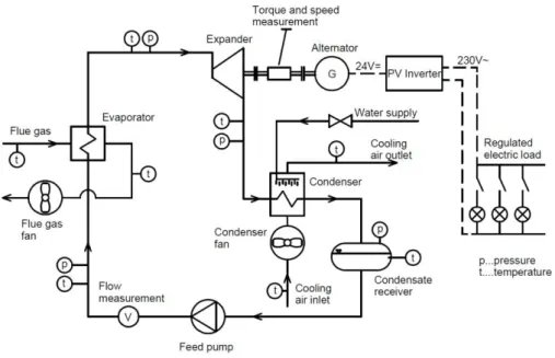
The experimental test rig with organic Rankine cycle at UCEEB is used for testing not only single components but also the whole cycle. Its scheme is shown in figure 1. ORC is designed as single-circuit. In the working fluid (MM)is dissolved about 5% of lubricating oil. Heat input to the cycle is approximately 20-23 kW. Main components are the evaporator, the expander, the condenser, the condensate receiver and the feed pump. Evaporator is a spiral tube exchanger. Flue gas from diesel burner is used as a source of heat. Flue gas inlet temperature ranges between 370 °C and 410 °C, outlet temperature is between 100°C and 130°C.
Figure 1: Scheme of the test rig
Generated vapor comes into a vane expander of own design. The expander is connected directly with the evaporator without any control valve. The expander drives a 24 VDC automotive alternator, which is connected with a common photovoltaic inverter. Bulbs with a total power consumption of 635 W are used as an electric load. Regulation step is 5 W. It is possible to connect additional load with constant power consumption as well. Condenser is similar to evaporator. It is a spiral tube exchanger designed with focus on low pressure drop. Condensation occurs inside the tubes. Condenser is air-cooled; fan speed is regulated by frequency inverter. Cooling air temperature at the inlet was about
Paper ID: 136, Page 3
30 – 35 °C. Water sprinkler that improves the cooling performance of the condenser was mounted above the condenser to decrease the condensing pressure even more. Condenser is followed by condensate receiver under which is placed a gear pump. The pump is connected with an asynchronous motor with nominal speed of 1500 RPM. Speed can be regulated with frequency inverter. Maximum flow is 8.5 l/min at nominal speed.
Position of all sensors can be seen in figure 1. The test rig allows measurement of temperatures at important points of the cycle, pressures, volumetric flow at the pump outlet, shaft speed of the expander and torque. Temperature of the flue gas at evaporator inlet and outlet and cooling air temperature at condenser inlet and outlet is also measured. Unfortunately it is not possible to measure the flow of flue gas and cooling air reliably. All the temperatures are measured with Pt100 sensors. Pressures are measured with common industrial piezoresistive pressure transducers. Turbine flow meter with pulse output is used for measurement of volumetric flow. Torque and speed is measured within one sensor – speed with pulse output, torque with bridge strain gauge with transducer. The data from the sensors are collected with common industrial PLC. Table 1 summarizes accuracy of used sensors.
Sensor Range Accuracy
Pressure - low pressure side (0-400) kPa abs. ±0.5% f.s. Pressure - high pressure side (0-1000) kPa abs. ±0.5% f.s. Temperature (-196 - +600) °C ±(0.30°C+0.005|t|)
Volumetric flow (1-10) l/min ±3% of reading
Torque (0-30) Nm ±0.2% f.s.
Speed (0-15000) RPM ±0.2% f.s.
Table 1: Range and accuracy of used sensors
Different working conditions can be reached in several ways. The shaft speed of expander can be regulated by switching the electric bulbs on and off. Decrease in the electric load results in torque reduction of alternator and shaft speed increase. Superheating of vapor can be influenced by changing the speed of pump. Lower speed leads to lower flow rate through the evaporator and larger superheating. Pressure in condenser and isentropic enthalpy gradient of expander can be influenced by changing the speed of the condenser fan and by use of the additional cooling with the water sprinkler. Performance of diesel burner slightly varied during the experiments due to decreasing of the level of fuel in a tank. Unfortunately this phenomenon cannot be controlled.
3. PROTOTYPE OF VANE EXPANDER
Expander is one of the most important components of the ORC. Its performance has significant impact on the efficiency of the whole cycle. As already written, expansion is ensured by the vane expander. This prototype was designed and built because there is no commercially available and cheap expander with a low power output of several kW. Vane expander was selected because of simple design, low manufacturing costs, reliability and possibility of reaching good thermodynamic efficiency in case of optimal design (Aoun, 2008). Design of tested expander is shown in figure 2. Expander is semi-hermetical;torque transmission is ensured by a magnetic coupling with permanent magnets. Stator is designed as a monoblock, in which a cylindrical working space, space for bearings and inlet and outlet chamber are milled. Supply and exhaust of the working fluid is radial. Rotor faces with bearings are mounted to the rotor with bolts. The bearings are placed in the stator with radial clearance, the axial movement of rotor is allowed. Rotor faces have grooves which serve for guiding the vanes during rotation. Rotor faces also create boundary of the working chambers. All the parts of the expander are made of stainless steel except the vanes, which are made of graphite. Expander has 8 working chambers with displacement of 7.66 cm3 per one chamber. Nominal built-in volumetric expansion ratio is 3. Expander is designed to produce 1 kW of mechanical power with overall efficiency of 0.41 at the nominal conditions of the cycle. Nominal shaft speed is 3020 RPM.
Paper ID: 136, Page 4
Figure 2: Design of the vane expander
It is necessary to ensure permanent contact of vanes with the inner stator surface for a proper function of the expander so that the working chambers are separated and there is no flow between adjacent chambers. Vanes are drawn out due to centrifugal force but only in case that this force is greater than a force resulting from the pressure difference above and below the vanes. Force resulting from pressure difference can be much higher than the centrifugal force especially during the initial phase of expansion. Therefore each slot for the vane in the stator has two milled grooves which connect working chamber with the space below the vane to balance the pressures. Similar solution is described by Peterson and McGahan (1972) for a vane compressor with the difference that the grooves are milled in the vanes. Another solution is to use the springs below the vanes as described e.g. by Yang
et al. (2008).
4. EXPERIMENTAL CAMPAIGN
The measured data were recorded every second during the experiments. They were evaluated always in steady states. All the recorded values were averaged at each stable state with a period of 3 to 7 minutes. 60 steady states were captured and evaluated.
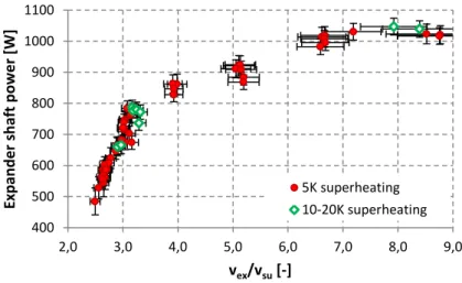
Figure 3: Measured values of expander shaft power
Admission temperature ranged from 135 to 157°C, admission pressure from 221 to 296 kPa abs., discharge pressure from 27 to 117 kPa abs. Superheating of admission vapor was maintained
400 500 600 700 800 900 1000 1100 2,0 3,0 4,0 5,0 6,0 7,0 8,0 9,0 Exp an d e r sh aft p o we r [W] vex/vsu [-] 5K superheating 10-20K superheating
Paper ID: 136, Page 5
at 5 K (±0.5K) during most of measurements. Several states were measured with the superheating of 10-20 K. Figure 3 shows dependence between expander shaft power and a ratio of specific volume of vapor at expander outlet and inlet (vex/vsu). It can be seen that the performance rises rapidly in the area where vex/vsu = 2.5-3.2.
Figure 4: Expander isentropic efficiency vs. vex/vsu
The expander isentropic efficiency defined in equation 1 is shown in figure 4.
)
(
su ex,s wf shaft sh
h
M
W
(1)Rapid increase of efficiency can be seen in the same range of values vex/vsu. The highest values of expander efficiency are at vex/vsu = 3.2. This value approximately corresponds to the built-in volumetric expansion ratio of the expander (rv,in=3). The efficiency falls in case that the value vex/vsu is higher than approximately 3.5. Performance of the expander ranged from 480 to 1050 W. Expander efficiency ranged from 0.4 to 0.58. Efficiency curve corresponds to the theoretical model. Fluctuation of values of efficiency is caused mainly because of a fluctuation of speed and, to a lesser extent, probably due to other effects. The points with superheating of 10-20 K are also highlighted in the graph in fig. 4. Only 10 stable states were measured in these conditions. It can be seen that the higher superheating mean higher efficiency in all cases. However, this fact is needed to be confirmed by further measurements. The dependence between expander efficiency and admission vapor superheating should be also measured in the future.
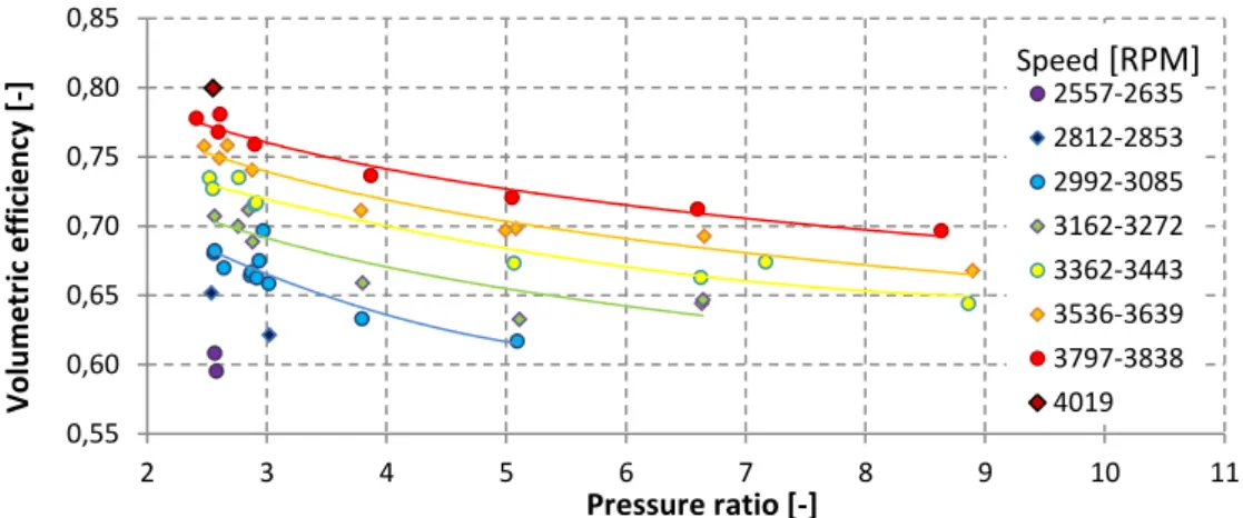
Figure 5: Volumetric efficiency vs. pressure ratio and speed, 5K superheating
0,40 0,42 0,44 0,46 0,48 0,50 0,52 0,54 0,56 0,58 0,60 2,0 3,0 4,0 5,0 6,0 7,0 8,0 9,0 Exp an d e r is e n tr o p ic e ff ic ie n cy [ -] vex/vsu [-] 5K superheating 10-20K superheating 0,55 0,60 0,65 0,70 0,75 0,80 0,85 2 3 4 5 6 7 8 9 10 11 Vo lu m e tr ic e ff ic ie n cy [ -] Pressure ratio [-] 2557-2635 2812-2853 2992-3085 3162-3272 3362-3443 3536-3639 3797-3838 4019 Speed [RPM]
Paper ID: 136, Page 6
Figure 5 shows the dependency of volumetric efficiency (which is defined by the equation 2) on pressure ratio and expander shaft speed. Shaft speed ranged from approximately 2550 to 4000 RPM.
su wf c rot vol v M V c N 60 exp ,
(2)It was difficult to maintain precise speed of expander due to characteristics of built-in regulator in alternator. For this reason the speed and the volumetric efficiency fluctuate a bit. Nevertheless it can be seen that the value of volumetric efficiency rises with the increase of speed. This is caused by rising of the overall flow through the expander when the total leakage within the expander remains almost the same. There is also declining trend of volumetric efficiency with increasing of pressure ratio within the expander. Higher pressure ratio leads to greater leakage of working fluid from the working chambers of the expander.
5. MODELING
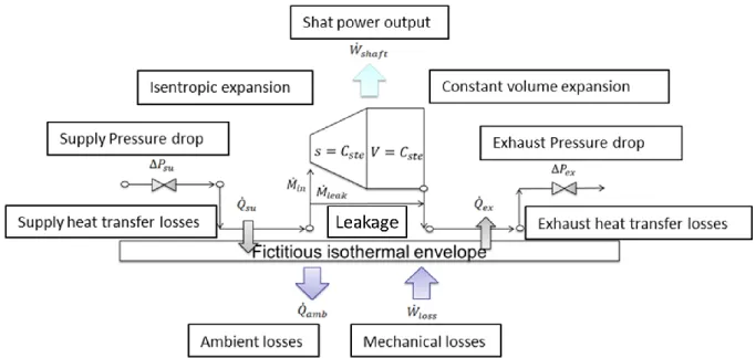
A semi-empirical model was calibrated on the base of the measured data. This lumped-parameter model takes into consideration major losses of the expander such as supply and discharge pressure losses, under and over-expansion, internal leakages and mechanical losses (figure 6). The model parameters were identified for the expander under investigation, integrated into a Rankine cycle and fed with hexamethyldisiloxane.
Figure 6: Schematic of the semi-empirical model
The parameter identification process was illustrated by Lemort (2009). The input variables of the model are the supply pressure, the supply temperature, the exhaust pressure and the rotational speed of the expander. The model then calculates the mass flow rate displaced by the expander, the delivered mechanical power and the exhaust temperature. A particular attention was dedicated to the identification of the leakage area parameter. Indeed, as it can be seen, this parameter almost evolves as the inverse of the rotational speed (figure 7). But it could also be shown that it depends on the pressure difference over the expansion machine and of the fluid inlet temperature.
Paper ID: 136, Page 7
Figure 7: Identification of the fictive flow rate area
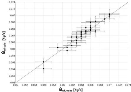
The validation of the model was realized comparing the predicted and measured values for the mass flow rate, mechanical power and the exhaust temperature of the expander. Figure 8 compares the evolutions of the mass flow rate measured and predicted by the model. It can be observed that the agreement between the measurement and the prediction by the model is very good. The maximum deviation is 3%.
Figure 8: Validation of the expander model - comparison between predicted and measured mass flow rate
The evolutions of the shaft power, measured and predicted by the model are compared in Figure 9. It can be observed that the agreement is good. The maximum deviation between the model predictions and the measurements is 8%.
Paper ID: 136, Page 8
Figure 9: Validation of the expander model - comparison between predicted and measured shaft power
The model predicts the exhaust temperature within 4 K and seems to slightly underestimate it. This could be – among other things – the result of an error in the temperatures measurements during the experimental campaign. Indeed, the energy balance over the expander revealed to be incorrect and led to negative ambient losses (see equation 3). However, the balance is very sensitive to precise temperature measurement and small errors have a great influence on the difference (hsu – hex).
0 ) ( wf su ex shaft amb M h h W Q (3)
Figure 10: Validation of the expander model - comparison between predicted and measured exhaust temperature
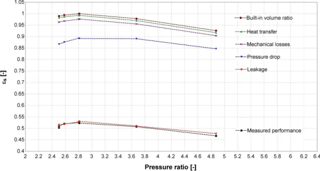
The validated model of the expander can then be used to quantify the different losses. Figure 11 shows the evolution of the overall isentropic efficiency with the pressure ratio imposed to the expander for a particular rotational speed of 3000 RPM. The evolution at the top of the figure is
Paper ID: 136, Page 9
predicted by a model that only accounts for under- and over-expansion losses. The efficiency equals 1.0 at a pressure ratio adapted to the built-in volume ratio (rv, in = 3) of the expander (top curve). For smaller and larger pressure ratios, the fluid is over-expanded and under-expanded respectively. The isentropic efficiency then decreases when accounting for the heat transfers (green curve) mainly because of the supply cooling down of the fluid. It also decreases when taking into account the mechanical losses (purple curve) mainly caused by the friction of the vanes on the stator. Introducing the supply pressure drop in the modeling largely reduces the isentropic effectiveness (blue curve). A more detailed investigation should answer the question of how to reduce this pressure drop by modifying the expander geometry. The internal leakage is responsible for the major part of the performance loss (red curve). Further work should investigate the possibility of reducing this leakage without increasing the mechanical losses of the expander.
Figure 11: Model analysis - evolution of the calculated overall isentropic effectiveness with the imposed pressure ratio for a rotational speed of 3000 RPM.
6. CONCLUSION
The paper describes experimental measurements and modeling of the vane expander prototype used in an experimental ORC which uses hexamethyldisiloxane as a working fluid. The ORC is cooled by air and uses flue gas as a source of heat. The vane expander reached the maximum shaft power of 1.05 kW with the isentropic efficiency 0.45. The maximum reached isentropic efficiency was 0.58 at 800 W of shaft power. It is obvious that highest efficiencies were obtained when the ratio vex/vsu roughly corresponds to the internal built-in volume ratio of the expander. Further attention should be paid to the optimal superheating which apparently affects the expander efficiency. Presented results of a semi-empirical model show good agreement between calculated and measured mass flow rate and shaft power respectively. The model shows that the internal leakage is responsible for the major part of performance loss. The supply pressure drop has also significant influence on the overall performance. Therefore, further work should be focused on investigation how to reduce these major losses.
NOMENCLATURE
c number of working chambers (–)
Paper ID: 136, Page 10
h specific enthalpy (J/kg)
M
mass flow rate (kg/s)Nrot rotational speed (RPM)
Q
heat transfer rate (W)rv, in internal built-in volumetric ratio (–)
s specific entropy (J/kg.K)
v specific volume (m3/kg)
V volume (m³)
Vc initial volume of working chamber (m 3 )
W
mechanical power (W) η, ε efficiency (–) Subscript amb ambient calc calculated ex exhaust exp expander in internal leak leakage loss losses meas measured s isentropic shaft shaft su supply vol volumetric wf working fluidREFERENCES
Aoun, B., 2008, Micro Combined Heat and Power Operating on Renewable Energy for Residential
Building,PhD thesis, École Nationale Supérieure des Mines de Paris, Paris, 151 p.
Cipollone, R., Contaldi, G., Bianchi, G., Murgia, S., 2014, Energy recovery using sliding vane rotary expanders, 8th International Conference on Compressors and their Systems, p.183-194.
Lemort, V., Quoilin, S., Cuevas, C., Lebrun, J., 2009, Testing and modeling a scroll expander integrated into an Organic Rankine Cycle , Applied Thermal Engineering, 29, p. 3094–3102. Mascuch, J., Dlouhy, T., 2011, Natural Gas Decentralized Micro CHP: The Czech Republic Case,
5th Annual International Travelling Conference for Young Researchers and PhD Students ERIN 2011,p. 81-86.
Peterson, C. R., McGahan, W. A., 1972, Thermodynamic and Aerodynamic Analysis Method for Oil Flooded Sliding Vane Compressor, International Compressor Engineering Conference, Purdue University, p. 1-8.
Xia, C., Zhang, W., Bu, G., Wang, Z., Shu, P., 2013, Experimental study on a sliding vane expander in the HFC410A refrigeration system for energy recovery, Applied Thermal Engineering, 59, p. 559–567.
Yang, B., Peng, X., He, Z., Guo, B., Xing, Z., 2008, Experimental investigation on the internal working process of a CO2 rotary vane expander, Applied Thermal Engineering, 29, p. 2289– 2296.
ACKNOWLEDGEMENT
This work has been supported by the European Union, OP RDI project No. CZ.1.05/2.1.00/03.0091 – University Centre for Energy Efficient Buildings and OP RDI project No. CZ.1.05/3.1.00/13.0283 – Intelligent Buildings.