HAL Id: hal-00974020
https://hal.inria.fr/hal-00974020
Submitted on 4 Apr 2014
HAL is a multi-disciplinary open access
archive for the deposit and dissemination of
sci-entific research documents, whether they are
pub-lished or not. The documents may come from
teaching and research institutions in France or
abroad, or from public or private research centers.
L’archive ouverte pluridisciplinaire HAL, est
destinée au dépôt et à la diffusion de documents
scientifiques de niveau recherche, publiés ou non,
émanant des établissements d’enseignement et de
recherche français ou étrangers, des laboratoires
publics ou privés.
Collaborative Virtual Environments for Ergonomics:
Embedding the Design Engineer Role in the Loop
Charles Pontonnier, Thierry Duval, Georges Dumont
To cite this version:
Charles Pontonnier, Thierry Duval, Georges Dumont. Collaborative Virtual Environments for
Er-gonomics: Embedding the Design Engineer Role in the Loop. 2014 International Workshop on
Collaborative Virtual Environments (3DCVE), IEEE VR, Mar 2014, Minneapolis, United States.
�hal-00974020�
DRAFT
Collaborative Virtual Environments for Ergonomics:
Embedding the Design Engineer Role in the Loop
Charles Pontonnier∗IRISA, Rennes, France Ecoles de Saint-Cyr Co ¨etquidan, Guer, France
Thierry Duval† IRISA, Rennes, France Universit ´e de Rennes 1,
Rennes, France
Georges Dumont‡ IRISA, Rennes, France ENS de Rennes, Bruz,
France
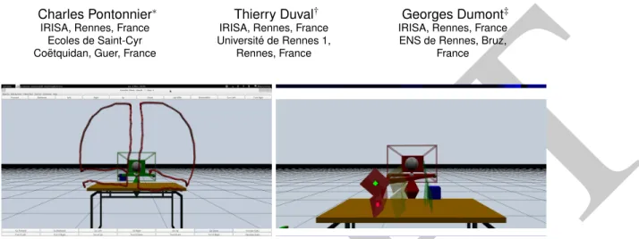
Figure 1: A user and an engineer are collaborating within a CVE through 3D annotations of the CVE. On the left is the engineer’s view of the user showing what are his maximum reachable limits. On the right is the user’s view of the the engineer placing some bounds in the CVE to show where the user cannot place a workstation element.
ABSTRACT
The aim of this paper is to define the role and duties of a design engineer involved in a collaborative ergonomic design session sup-ported by a 3D collaborative virtual environment. For example, such a session can be used to adapt the manual task an operator must achieve in the context of an industrial assembly line. We first present the interest of such collaborative sessions. Then we present a related work explaining the need of proper 3DCVE and metaphors to obtain efficient collaborative ergonomic design sessions. Then, after a short definition of the role of the engineer in such sessions, we propose a use case highlighting the type of metaphor such engi-neers need to have to be efficient in such a framework. Discussion and future works ends the paper.
Index Terms: H.5.2 [Information Interfaces and Presentation (e.g., HCI)]: User Interfaces—User-centered design; H.5.3 [In-formation Interfaces and Presentation (e.g., HCI)]: Group and Organization Interfaces—Computer-supported cooperative work; I.3.6 [Computer Graphics]: Methodology and Techniques— Ergonomics, Interaction techniques; I.3.7 [Computer Graphics]: Three-Dimensional Graphics and Realism—Virtual reality 1 INTRODUCTION
3D Collaborative Virtual Environments (3DCVE) have a great po-tential of application in the field of computer-aided design and computer-aided ergonomics [14]. Indeed, the use of virtual envi-ronments as a tool to support ergonomic assessments of worksta-tions is an old and compelling idea [22]. Wilson stated in his paper that such applications were still limited as technologies were lim-ited. Now, with regard to the rise of new technologies and mature 3DCVE, the use of such features in the early stage of workstations
∗e-mail: [email protected] †e-mail: [email protected] ‡e-mail: [email protected]
design seems natural since assessing ergonomics from the digital mock-up (DMU) is more cost-effective and convenient than doing it on a physical mock-up [6, 1]. However, many issues remain un-solved in order to generalize the use of 3DCVE as support tools for ergonomics and design of workstations. First, the reliability of the ergonomic assessment remains contrasted, as differences ex-ist in terms of motor control and sensory feedback between a real work situation and its emulation in VE [16, 14]. Then, 3DCVE will be efficient for workstation design and ergonomics only if the dif-ferent actors involved in the design process, i.e. design engineers, ergonomists and final users (industrial workers) have the opportu-nity to interact with each other and with the 3DCVE in a convenient way. It seems mandatory to allow these three actors to interact with each other. Indeed, the design engineer warrants the process con-straints to be fulfilled while the ergonomist warrants the respect of the ergonomic constraints. At last the final user warrants that the workstation is adapted to his morphological and physical fea-tures according to the task to complete. In a previous paper, we explored ways to share and bridge properly information between the ergonomist and the final user in a collaborative ergonomics de-sign session [15]. In the current contribution, our aim is to properly define the role, duties and metaphors that are mandatory to involve design engineers in such sessions. For example, these sessions can be used to adapt the manual task an operator must achieve in the context of an industrial assembly line.
In a first section, we present the current research work related to the use of virtual reality (VR) and collaborative virtual environ-ments for design and ergonomics, focusing on collaborative virtual sessions particularly. Then, the role of the design engineer in a col-laborative design session is defined. As a consequence of this role definition, needs in terms of interaction metaphors are formulated and a sample use case is proposed to illustrate the way such inter-action metaphors can be realized.
2 VR-AIDED DESIGN ANDVR-AIDED ERGONOMICS
VR-tools have been successfully used in several early-stage er-gonomic studies. For example, VR has already been used to assess different ergonomics features of manual handling opera-tions [22, 6, 20] or boxes lifting operaopera-tions [21]. In such VR-based
DRAFT
applications, the user mimics real work tasks in interaction with a virtual environment representing the workstation. Mostly, motion tracking systems and haptic interfaces are used to define the interac-tion metaphors. In most cases, the ergonomist bases his analysis on kinematical data [8, 12], since postural metrics such as the RULA score [9] are easy to derivate from motion data and are widely used in ergonomic studies. Nevertheless, all of these studies are lim-ited because of the lack of possibility given to the ergonomist to actively and remotely indicate in the virtual world which motion is problematic and how to improve the user comfort. Indeed, the analysis of the tasks is done offline or directly in the same room as the main user, and the ergonomist provide his advices directly by speaking with the user. This is very constraining because it implies that both actors of the design are at the same place at the same time. This is not efficient because the ergonomist explains indirectly his thoughts about the work tasks to the user. Moreover, the ergonomic study is not correlated with the process specifications, whereas it seems mandatory to find a compromise between process efficiency and worker integrity during the design stage.
Several VR-aided design tools have also been developed and used successfully in the industry. For example, Boeing [17], Gen-eral Motors [7], Volkswagen [3] or Caterpillar [10] have been using simulations implemented on digital mock-ups in a virtual environ-ment to reduce the number of physical prototypes they ordinary use to develop a new product or a new fabrication process.
Since the assembly process represents a significant part of the cost of a product [2], assembly tasks have been massively stud-ied with VR-aided tools. Commercial CAD softwares are typically used to simulate the assembly process by manually selecting the mating surfaces, axes and/or edges to assemble the parts. Neverthe-less these softwares do not reflect human interaction with complex parts, especially the human factors of manipulation and control in-volved in such tasks. Moreover, CAD software based systems are unable to evaluate the ergonomics of the task, e.g. to detect awk-ward postures or peaks of muscular activity reached during assem-bly operations. To circumvent this crucial issue, haptics saw an outstanding development in the past few years. by using haptics technology, engineers can interact with complex CAD parts and adopt a realistic behavior and a natural motion when performing virtualized assembly tasks [19]. From an assessment point of view, a quantitative analysis concerning the significance of haptic inter-actions in performing simulations of manual assemblies was per-formed in [18].
To our knowledge, few collaborative ergonomics design sessions combining ergonomic evaluations and interventions, realistic vir-tual environments with natural interactions, and process and design specifications have been completely designed and implemented. The french research centre CLARTE1 developed several tools to
address ergonomic and design collaborative issues. For example, IMPROOV2is a complete solution of immersive and collaborative
virtual environment for ergonomics as well as process optimisation. It includes features such as the evaluation of postures (RULA score) and a collaborative environment via a web navigator that enables an intervention of external actors in the design process. This platform still presents some limitations: the interaction modes between the actors are limited and the intervention of the ergonomist is mainly done via the auditory channel. Nevertheless, this platform has been used widely and industrially with promising results.
To our knowledge, no existing tool enables ergonomists and de-sign engineers to propose gesture improvements or DMU modifica-tions directly via the VE. This is the purpose of the 3DCVE we are currently developing, and the current paper aims at defining proper methods and metaphors of collaboration between the final user and the design engineer.
1www.clarte.asso.fr
2http://www.clarte.asso.fr/realite-virtuelle.php/improov/
3 THE ROLE OF THE ENGINEER IN A COLLABORATIVE ER
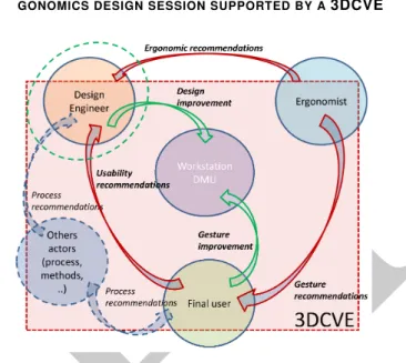
-GONOMICS DESIGN SESSION SUPPORTED BY A3DCVE Figure 2: A proposition of interaction definitions between the dif-ferent actors involved in a collaborative ergonomic design session supported by a 3DCVE with a ”direct design” operating mode. The role of the design engineer is highlighted in green. The figure is directly adapted from [15].
As shown in figure 2, a collaborative ergonomics design session consists in using a 3DCVE to simulate and evaluate the work task emulated from the digital mock-up of the workstation. The final user is asked to perform his work as he would do in real conditions. Measurements of biomechanical indicators (posture, muscle activ-ity) as well as performance indicators are used by both ergonomist and design engineers to enhance the ergonomics of the workstation and maintain its specifications with regard to the industrial process. The design engineer can have different roles, depending on the operating mode currently being used during the session. Accord-ing to the figure 2, the design engineer has to be able to take into account recommendations coming from both final user and er-gonomist, and to act on the DMU to indicate and to proceed to mod-ifications in accordance with the process specmod-ifications. In this op-erating mode, the design engineer has an active role as he is the only one allowed to modify the DMU. We can call this operating mode ”direct design” mode. In this operating mode, both ergonomist and final user need informative metaphors such as visual signals (ar-rows, spots, ...) and auditory signals (voice, bips,...) to highlight problematic parts of the workstation. Moreover, both final user and ergonomist need tools to show reachable positions and volumes to the design engineer. Then the design engineer has to be able to modify or move parts of the workstation with convenient manipu-lation techniques.
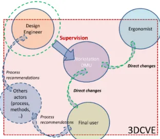
A second operating mode can be much more effective: in this case, according to figure 3, the design engineer is not acting directly on the DMU, but supervises, frames and validates with regard to its process expertise the changes made by the other actors. Here, changes are directly realized with regard to usability and ergonomic considerations, coming respectively from the final user’s experience and from the ergonomist’s analysis, and process specifications are guaranteed by the design engineer. In this operating mode, that we can call ”supervised design”, the design engineer needs tools, such as process information metaphors, to frame and indicate to the others actors if the modifications they plan to do are compatible with the process specifications. Such information metaphors will
DRAFT
Figure 3: A proposition of interaction definitions between the dif-ferent actors involved in a collaborative ergonomic design session supported by a 3DCVE with a ”supervised design” operating mode. The role of the design engineer is highlighted in green.
mostly consist in plans and volumes materializations.
The next section deals with two use cases illustrating respec-tively both ”direct design” and ”supervised design” operating modes. In the first example, the ergonomist or the final user aims at moving a specific element of the workstation and the design en-gineer indicates spatial limitations of displacement with regard to the process specifications. In the second case, the final user asks for modification of the position of an element and indicates to the design engineer a reachable volume where he can manipulate easily this element.
4 AUSE CASE: MOVING AN ELEMENT OF THE WORKSTA
-TION WITHIN INTERACTIVE SPATIAL LIMITA-TIONS
The chosen use case is a very common ergonomic intervention: an element of the workstation is not optimally placed and the final user needs to adopt uncomfortable postures to reach the element. Both ergonomist and final user request for a modification of the position of this element to the design engineer. Then all of the actors try to find a compromise between the user’s comfort and the process specifications, which consists in finding an intersection U ∩ V be-tween the reachable volume U defined by the final user (and maybe pondered by the ergonomist) and the volume defined by the design engineer with regard to the process specifications V . Figure 4 il-lustrates this use case. The use case has been implemented in the collaborative platform Collaviz3, using its distribution features [5]
and its abilities for modelling the physical spaces of the users of CVE [4].
The engineer has access to the process specifications thanks to the CAD software initially used to design the DMU. The DMU has been especially prepared to be used in a virtual environment, following the guidelines developed in [13]. In our example, the engineers knows that the left of the workbench where the element needs to be placed is already used for another process with regard to the specifications. This specification is shown in figure 5. Then the engineer is able to visualize and define a volume V compatible with the process specifications where the element can be placed. The final user does not have access to this information, to avoid confusion with the scene features he has to use when simulating the work tasks.
3Collaviz is publicly available at www.collaviz.org
Figure 4: The chosen use case aims at finding a position for an element of the workstation (in purple) satisfying both constraints: be reachable in a comfortable posture by the final user (be in volume U) and satisfying the process specifications (be in volume V ).
Figure 5: On the left: the DMU as defined in the CAD software. On the right: the definition of volume V specified by the design engineer after analysis of the DMU.
4.1 Direct design mode
In this case, when he wants to place the element of the workstation, the engineer has to follow the recommendations from the user or from the ergonomist. For example, the user or the ergonomist can express these recommendations through 3D annotations such as de-scribing the volume that can be easily reached by the user, which volume can be reached with more efforts, and what are the ultimate reachable limits. We have implemented a first tool enabling a user to express these three different kinds of bounds, as illustrated in fig-ure 6. The metaphor consists in a 3D pencil allowing the main user or the ergonomist to draw limits of a reachable volume. Extruded 3D objects are materializing these limits. The 3D objects can be drawn in 3 different colors, manually chosen by the main user to indicate the kind of bound he is drawing - green = easy, yellow = difficult, red = ultimate.
4.2 Supervised design mode
In this case the engineer has to propose limits to the positions pro-posed by the user or by the ergonomist.
For example, the user or the ergonomist can propose a new posi-tion for the the element of the workstaposi-tion, while the engineer can express recommendations through other kinds of 3D annotations, expressing if the modification has a low, medium or high impact on the global design of the workstation.
Here again, we have implemented some tools enabling an engi-neer to express these three different level impacts. A first metaphor is illustrated in figure 7: it consists in the manipulation and the fix-ing of translucent planes manually colored with a green-to-red color scale indicating the impact of the use of these bounds on the whole process. After having deposed such planes, the engineer can chose
DRAFT
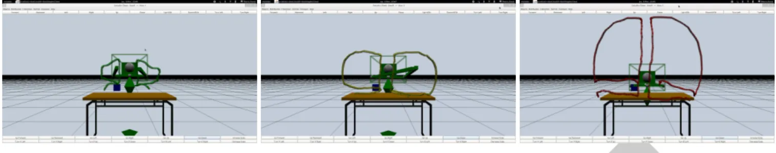
Figure 6: Engineer’s points of view in direct design mode while the user is indicating the whole area that he can reach easily (image on the left), with little difficulty (image at the center) and with efforts (image on the right)
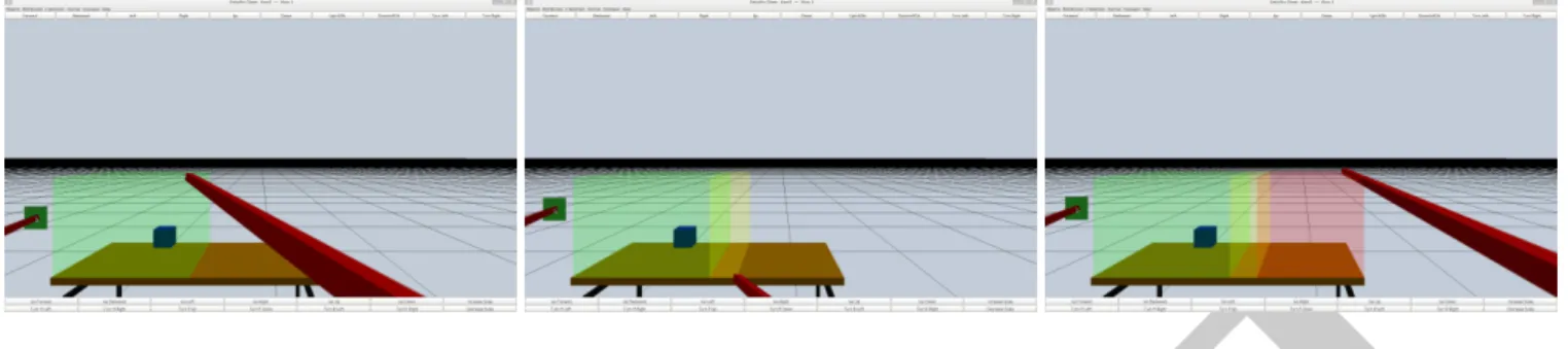
Figure 7: User’s point of view in supervised design mode: the engineer has indicated in green some safe limits to the main user (image on the left), then he has added some further limits in yellow that he would not like to be trespassed (image at the center), and last he has added in red the ultimate limits (image on the right).
to change their position or orientation, he can also remove them. This first metaphor is mainly dedicated to show dynamically these bounds to the user and to the ergonomist.
A second metaphor is illustrated in figure 8: this time it consists in the creation of translucent volumes with the same color-scale convention indicating the impact of the use of these bounds on the whole process. The engineer can use this second metaphor dynam-ically during the user’s interaction, and he can also create these bounds prior to the interaction of the user and the ergonomist in order to prepare the virtual environment.
The Engineer can control two different tools with his two hands: they can be of the same kind (two volume delimiters based either both on portion of planes or based both on bounding boxes) or of different kinds (each hand controlling a different metaphor). This choice is up to the engineer because he can switch from one tool to another one whenever he wants.
5 CONCLUSION AND FUTURE WORKS
This paper aimed at introducing two operating modes and their cor-responding interaction metaphors to allow a design engineer to in-tervene in a collaborative ergonomics design session supported by a 3DCVE. We presented two operating modes respectively called ”direct design” and ”supervised design mode”.
In ”direct design” mode, the design engineer needs a good in-terpretation of the 3D scene to fully understand the volumes the final user is drawing. Currently, our solution consists in a draw-ing of consecutive extruded volumes. It makes a good delimitation of the volume possible, but a great improvement of this metaphor consists in filling with transparency the volume to help the other users to better apprehend the final user’s reachable zone. Moreover, the way the final user is drawing the volumes can be improved by standardizing the drawing procedure. For example, the front reach-able zone (a quarter sphere) can be easily drawn in four steps as shown in figure 9. At last, this mode could be enhanced by the intervention of the ergonomist. Currently, the final user chooses
manually a color -green, yellow and red- to indicate if the volume he draws is respectively easily reachable, moderately reachable or hardly reachable. We can think that in a near future, reachable vol-umes can be colored automatically on the basis of postural scores as they are calculated in [15] with a green-to-red color scale, indicat-ing automatically which part of the reachable volume is the most comfortable for the final user. The ergonomist can then use this information with regard to all the available specifications on the process and the workstation, in order to help the engineer to make a decision about the final position of the workstation’s element. For example he could use arrows or light metaphors [11] to highlight the most appropriate zones.
Figure 9: Drawing procedure for the front reachable volume. The subject begins with a T-pose and follows the four steps described in the figure to draw a quarter sphere.
In ”supervised design” mode, the design engineer needs an ac-curate manipulation of the plans and volumes to properly put them
DRAFT
Figure 8: Engineer’s point of view in supervised design mode: the engineer has indicated in green some safe bounds to the main user (image on the left), then he has added some further bounds in yellow that he would not like to be trespassed (image at the center), and last he has added in red the bounds that must absolutely not be reached (image on the right).
down in the 3D scene. Currently, no additional feature helps the engineer to do so. We are trying to solve this issue and a solution could be to associate visual guides with the plans and volumes in order to align them with the geometrical shapes of the workstation (e.g. a table edge, a work plan surface, a wall). In other words, when the plan or the volume is close enough to a recognized shape, it can be put down in alignment with this shape automatically. In a similar way to the automatic coloration of the reachable volumes, we also think about choosing automatically the color of the plans and volumes on the basis of their distance with the process bounds. The current paper is a work in progress, and additional work is needed to fully develop and validate these operating modes and metaphors. We plan to validate and compare the operating modes and metaphors with a simple experimental protocol, asking two subjects to solve the use case with all the possible combinations. With a sufficient pool of subject and a sufficient amount of trials, we should be able to determine which operating mode is the most efficient one.
REFERENCES
[1] G. Backstrand, D. Hogberg, L. J. D. Vin, K. Case, and P. Piamonte. Ergonomics analysis in a virtual environment. International Journal of Manufacturing Research, 2:198–208, 2007.
[2] G. Boothroyd and P. Dewhurst. Product design for assembly. McGraw-Hill, New York, 1989.
[3] F. Dai, W. Felger, T. Fr¨uhauf, M. G¨obel, D. Reiners, and G. Zach-mann. Virtual prototyping examples for automotive industries. In Virtual Reality World, 1996.
[4] C. Fleury, A. Chauffaut, T. Duval, V. Gouranton, and B. Arnaldi. A generic model for embedding users’ physical workspaces into multi-scale collaborative virtual environments. ”ICAT 2010 (20th Interna-tional Conference on Artificial Reality and Telexistence)”, 2010. [5] C. Fleury, T. Duval, V. Gouranton, and B. Arnaldi. A New Adaptive
Data Distribution Model for Consistency Maintenance in Collabora-tive Virtual Environments. In JVRC 2010 (2010 Joint Virtual Real-ity Conference of EuroVR - EGVE - VEC), Fellbach, Germany, Sept. 2010.
[6] U. Jayaram, S. Jayaram, I. Shaikh, Y. Kim, and C. Palmer. Introduc-ing quantitative analysis methods into virtual environments for real-time and continuous ergonomic evaluations. Computers in Industry, 57(3):283 – 296, 2006.
[7] G. Kobe. Virtual interiors. Automotive Industries, 175(5):52–54, 1995.
[8] D. Mavrikios, M. Pappas, M. Kotsonis, V. Karabatsou, and G. Chrys-solouris. Digital humans for virtual assembly evaluation. In Digital Human Modeling, Lecture Notes in Computer Science, pages 939– 948. 2007.
[9] L. McAtamney and E. N. Corlett. RULA : A survey method for the investigation of work-related upper limb disorders. Applied Er-gonomics, 24(2):91–99, 1993.
[10] M. M¨uller, J. Dorsey, L. McMillan, R. Jagnow, and B. Cutler. Sta-ble real-time deformations. In Proceedings of the 2002 ACM SIG-GRAPH/Eurographics symposium on Computer animation, pages 49– 54. ACM, 2002.
[11] T. T. H. Nguyen, T. Duval, and C. Fleury. Guiding Techniques for Col-laborative Exploration in Multi-Scale Shared Virtual Environments. In Proceedings of GRAPP International Conference on Computer Graphics Theory and Applications, pages 327–336, Barcelona, Spain, february 2013.
[12] M. Pappas, V. Karabatsou, D. Mavrikios, and G. Chryssolouris. Er-gonomic evaluation of virtual assembly tasks. In Digital Enterprise Technology, pages 511–518. 2007.
[13] C. Pontonnier, G. Dumont., A. Samani, P. Madeleine, and M. Badawi. Designing and evaluating a workstation in real and virtual environ-ment: from digital mock-up to realization. In 3rd IEEE International Conference on Cognitive Infocommunications (CogInfoCom 2012), 2012.
[14] C. Pontonnier, G. Dumont, A. Samani, P. Madeleine, and M. Badawi. Designing and evaluating a workstation in real and virtual environ-ment: toward virtual reality based ergonomic design sessions. Journal on Multimodal User Interfaces, pages 1–10, 2013.
[15] C. Pontonnier, T. Duval, and G. Dumont. Sharing and bridging in-formation in a collaborative virtual environment: Application to er-gonomics. In 4th IEEE International Conference on Cognitive Info-communications (CogInfoCom 2013), 2013.
[16] C. Pontonnier, A. Samani, M. Badawi, P. Madeleine, and G. Dumont. Assessing the ability of a vr-based assembly task simulation to evalu-ate physical risk factors. IEEE transactions on visualization and com-puter graphics, In Press, 2013.
[17] B. Schmitz. Great expectations-the future of virtual design. Computer-Aided Engineering, 14(10):68, 1995.
[18] D. M. Vo, J. M. Vance, and M. G. Marasinghe. Assessment of haptics-based interaction for assembly tasks in virtual reality. World Haptics Conference, pages 494–499, 2009.
[19] S. Volkov and J. M. Vance. Effectiveness of haptic sensation for the evaluation of virtual prototypes. ASME Journal of Computing and Information Sciences in Engineering, 1(2):123–128, 2001.
[20] Y. Wang, K. Liao, Y. Guo, Y. Zhang, W. Zhang, and S. Wu. De-velopment and application of integrated human machine interaction simulation system. Journal of System Simulation, 19(11):2492–2495, 2007.
[21] L. E. Whitman, M. Jorgensen, K. Hathiyari, and D. Malzahn. Vir-tual reality: its usefulness for ergonomic analysis. In Proceedings of the 36th conference on Winter simulation, pages 1740–1745. Winter Simulation Conference, 2004.
[22] J. R. Wilson. Virtual environments applications and applied er-gonomics. Applied Ergonomics, 30(1):3 – 9, 1999.