HAL Id: hal-00145163
https://hal.archives-ouvertes.fr/hal-00145163
Submitted on 8 May 2007HAL is a multi-disciplinary open access archive for the deposit and dissemination of sci-entific research documents, whether they are pub-lished or not. The documents may come from teaching and research institutions in France or abroad, or from public or private research centers.
L’archive ouverte pluridisciplinaire HAL, est destinée au dépôt et à la diffusion de documents scientifiques de niveau recherche, publiés ou non, émanant des établissements d’enseignement et de recherche français ou étrangers, des laboratoires publics ou privés.
Kinematic Calibration of the Orthoglide-Type
Mechanisms
Anatol Pashkevich, Damien Chablat, Philippe Wenger
To cite this version:
Anatol Pashkevich, Damien Chablat, Philippe Wenger. Kinematic Calibration of the Orthoglide-Type Mechanisms. 2006, Saint Etienne, France. pp.1-6. �hal-00145163�
KINEMATIC CALIBRATION OF ORTHOGLIDE-TYPE MECHANISMS Anatoly Pashkevich1,2, Damien Chablat2
, Philippe Wenger2
1
Robotic Laboratory, Department of Automatic Control Belarusian State University of Informatics and Radioelectronics 6 P.Brovka St., Minsk 220027, Belarus, e-mail: pap@bsuir.unibel.by
2
Institut de Recherche en Communications et Cybernétique de Nantes 1, rue de la Noë B.P. 6597, 44321 Nantes Cedex 3, France e-mals: {Damien.Chablat, Philippe.Wenger }@irccyn.ec-nantes.fr
Abstract: The paper proposes a novel calibration approach for the Orthoglide-type
mechanisms based on observations of the manipulator leg parallelism during mo-tions between the prespecified test postures. It employs a low-cost measuring system composed of standard comparator indicators attached to the universal magnetic stands. They are sequentially used for measuring the deviation of the relevant leg location while the manipulator moves the TCP along the Cartesian axes. Using the measured differences, the developed algorithm estimates the joint offsets that are treated as the most essential parameters to be adjusted. The sensitivity of the meas-urement methods and the calibration accuracy are also studied. Experimental re-sults are presented that demonstrate validity of the proposed calibration technique.
Keywords: parallel robots, kinematic calibration, model identification, joint offsets, and error compensation.
1. INTRODUCTION
Parallel kinematic machines (PKM) are commonly claimed to offer several advantages over serial ma-nipulators, like high structural rigidity, better pay-load-to-weight ratio, high dynamic capacities and high accuracy (Merlet, 2000; Tlusty, et al., 1999). As stated by a number of authors (Tsai, 1999; Wenger,
et al., 1999), the conventional serial kinematic
struc-tures have already achieved their performance limits, which are bounded by high component stiffness re-quired to support sequential joints, links and actua-tors. Thus, the PKM are prudently considered as promising alternatives to their serial counterparts that offer faster, more flexible, more accurate and less costly solutions.
However, while the PKM usually demonstrate a much better repeatability compared to serial mecha-nisms, they may not necessarily posses a better accu-racy, which is limited by manufacturing/assembling errors in numerous links and passive joints (Wang, and Masory, 1993). Besides, for the non-Cartesian parallel architectures, some kinematic parameters (such as the encoder offsets) cannot be determined by direct measurement. These motivate intensive re-search on PKM calibration.
Similar to the serial manipulators, the PKM calibra-tion procedures are based on the minimisacalibra-tion of a parameter-dependent error function, which incorpo-rates residuals of the kinematic equations. For the parallel manipulators, the inverse kinematic
equa-tions are considered computationally more efficient, since the most of the PKM admits a closed-form so-lution of the inverse kinematics (Innocenti, 1995; Iurascu, and Park, 2003; Huang, et al., 2005). But the main difficulty with the inverse-kinematics-based calibration is the full-pose measurement requirement, which is very hard to implement accurately (Jeong,
et al., 2004.
Recently, several hybrid calibration methods were proposed that utilize intrinsic properties of a particu-lar parallel machine allowing to extract the full set of the model parameters (or the most essential of them) from a minimum set of the pose error measurements. An innovative approach for the I4 parallel mecha-nism has been developed by Renaud et al (2004, 2006) who applied vision to perform measurement on manipulator legs, which connect the end-effector to the base-mounted linear actuators.
This paper focuses on the Orthoglide-type mecha-nisms, which kinematic architecture admits parallel leg motions (along the longitudinal axis). From ob-servations the leg parallelism at prespecified pos-tures, the proposed calibration algorithm estimates the joint offsets that are treated as the most essential parameters to be adjusted. The main advantage of this approach is the simplicity and low cost of the measuring system composed of standard comparator indicators attached to the universal magnetic stands. They are sequentially used for measuring the devia-tion of the relevant leg locadevia-tion while the manipula-tor moves the TCP along the Cartesian axes.
The remainder of the paper is organised as follows. Section 2 describes the manipulator geometry, its inverse and direct kinematics, and also contains the sensitivity analysis of the leg parallelism at the ex-amined postures with respect to the joint offsets. Sec-tion 3 focuses on the measurements and parameter identification. Section 4 contains experimental re-sults and their discussion, while Section 5 summa-rises the main results.
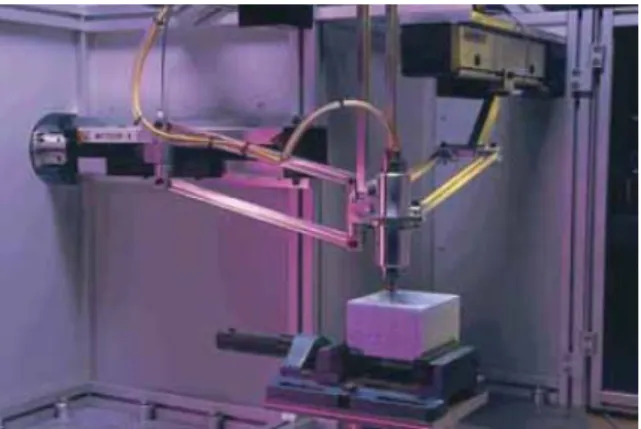
Fig. 1. The Orthoglide mechanism
2. KINEMATIC MODEL
2.1 Manipulator geometry
The Orthoglide is a three degree-of-freedom mecha-nism actuated by three linear drives with mutually orthogonal axes (Chablat and Wenger, 2003). Its kinematic architecture is presented in Fig. 1 and in-cludes three identical parallel chains that are formally described as PRPaR, where P, R and Pa denote the prismatic, revolute, and parallelogram joints.
The mechanism input is made up by three actuated orthogonal prismatic joints. The output machinery (with a tool mounting flange) is connected to the prismatic joints through a set of three kinematic chains that further referred as manipulator “legs”. The legs are made with articulated parallelograms that are oriented in a manner that the output body is restricted to the translational movements only. A specific feature of the Orthoglide mechanism, which will be further used for the calibration, is dis-played during the end-effector motions along the Cartesian axes. For example, for the x-axis motion in the Cartesian space, the sides of the x-leg parallelo-gram must also retain strictly parallel to the x-axis. Hence, the observed deviation of the mentioned par-allelism may be used as the data source for calibra-tion algorithms.
2.2 Modelling assumptions
Following previous studies on the parallel mecha-nism accuracy (Wang, and Massory, 1995, Renaud,
et al., 2004; Caro, et al., 2006), the influence of the
joint/link defects is assumed negligible compared to the joint positioning errors mainly caused by the en-coder offsets. This validates the following modelling assumptions:
(i) the manipulator parts are supposed to be rigid-bodies connected by perfect joints;
(ii) the articulated parallelograms are assumed to be identical and perfect, which insure that their sides stay parallel in pares for any motions; (iii) the manipulator legs (composed of one
pris-matic joint, one parallelogram, and three revo-lute joints) are identical and generate a five-DOF motion each;
(iv) the linear actuator axes are considered mutually orthogonal and intersected in a single point to insure a translational three-DOF movement of the end-effector.
The actuator encoders are assumed to be perfect but their location (zero position) is defined with some errors that are treated as the offsets to be estimated. Using these assumptions, there will be developed a convenient calibration methodology based on the observation of the parallel gel motions.
2.3 Basic equations
Under the above assumptions, the Orthoglide can be presented by a simplified model, which consists of three rod-links connected by spherical joints to the tool centre point (TCP) at one side and to the corre-sponding prismatic joints at another side. Thus, if the origin of a reference frame is located at the intersec-tion of the prismatic joint axes and the x, y, z-axes are directed along them, the manipulator geometry may be described by the equations
[
]
2 2 2 2 ) ( p p L px− ρx+Δρ + y+ z =[
]
2 2 2 2 ) ( p L p px+ y− ρy+Δρy + z = (1)[
]
2 2 2 2 p p ( ) L px+ y+ z− ρz+Δρz =where p = (px, py, pz) is the output position vector,
ρ = (ρx, ρy, ρz) is the input vector of the joints
vari-ables, Δρ = (Δρx, Δρy, Δρz) is the encoder offset
vec-tor, and L is the length of the parallelogram principal links. Hence, within the adopted model, four parame-ters (Δρx, Δρy, Δρz, L) define the manipulator
geome-try, but because of the rather tough manufacturing tolerances, the leg length is assumed to be known and only the joint offsets (Δρx, Δρy, Δρz) are in the
focus of the proposed calibration technique.
It should be noted that for the nominal ‘‘mechanical-zero’’ posture corresponding to the joints variables ρ0 = (L, L, L), the x-, y- and z-legs are oriented
strictly parallel to the relevant Cartesian axes. But the joint offsets cause the deviation of the “zero” location and corresponding deviation of the leg par-allelism with respect to the manipulator base surface. The latter may be (i) measured and (ii) computed applying the direct kinematic algorithm for the joint variables ρ = (L+Δρx, L+Δρy, L+Δρz). However, the
capability of this simple technique is limited by evaluating the offset of the z-axis encoder only, since the Orthoglide mechanical design does not allow making similar measurements for the remaining pairs of the legs, with respect to the xz- and yz-planes.
2.4 Inverse and direct kinematics
To derive calibration equations, first let us expand some previous results on the Orthoglide kinematics (Pashkevich et al., 2005) taking into account the en-coder offsets. The inverse kinematic relations are derived from the equations (1) in a straightforward way and only slightly differ from the “nominal” case
x z y x x x= p +s L −p − p −Δρ ρ 2 2 2 y z x y y y =p +s L −p −p −Δρ ρ 2 2 2 (2) z y x z z z =p +s L −p −p −Δρ ρ 2 2 2
where sx, sy, sz ∈ { ±1} are the configuration indices
defined for the “nominal” manipulator as signs of
(ρx –px), (ρy –py), and (ρz –pz) respectively. It is
ob-vious that expressions (2) define eight different solu-tions to the inverse kinematics, however the Or-thoglide assembling and joint limits reduce this set for a single case corresponding to the sx=sy=sz=1.
For the direct kinematics, the equations (1) can be subtracted pair-to-pair that gives the following ex-pression for the unknowns px, py, pz
} , , { ; 2 i x y z t p i i i i i +ρ +Δρ ∈ ρ Δ + ρ = (3)
where t is an auxiliary scalar variable. This reduces the direct kinematics to the solution of a quadratic equation at2+bt+c=0 with the coefficients
; ) )( (
∏
≠ ρ Δ + ρ ρ Δ + ρ = j i j j i i a =∏
ρ +Δρ i i i b ( )2; ; 4 ) ( 2 2∑
ρ +Δρ − = i i i L c i,j∈{x,y,z}From two possible solutions that give the quadratic formula, the Orthoglide prototype (see Fig. 1) admits only one expressing as t= − +( b m b2−4ac) / 2a.
2.5 Sensitivity analysis
To evaluate the encoder offset influence on the legs parallelism with respect to the Cartesian planes XY,
YZ, and YZ, let us derive the differential relations for
the TCP deviation for three types of the Orthoglide postures: mechanical zero” posture and
“maxi-mum/minimum displacement” postures for the
direc-tions x, y, z. These postures are of particular interest for the calibration since in the “nominal” case (no encoder offsets) at least one leg is parallel to the cor-responding pair of the Cartesian planes.
The desired differential relations may be derived from the Orthoglide Jacobian, the inverse of which is obtained from (1) as 1 1 ( , ) 1 1 y z x x x x x z y y y y y x z z z z p p p p p p p p p p p p ρ ρ ρ ρ ρ ρ − ⎡ ⎤ ⎢ ⎥ − − ⎢ ⎥ ⎢ ⎥ ⎢ ⎥ = − − ⎢ ⎥ ⎢ ⎥ ⎢ ⎥ ⎢ − − ⎥ ⎣ ⎦ J p ρ (4)
For the “mechanical zero” posture, the differential relations are derived in the neighbourhood of the point p0 = (0, 0, 0) and ρ0 = (L, L, L), which gives the
identity Jacobian matrix J p ρ( 0, 0)=I3 3× . Hence, in this case the TCP displacement is related to the joint offsets by trivial equations Δpi=Δρi; i∈{x,y,z}. Taking into the account the Orthoglide geometry, this deviation may be estimated by evaluating parallelism of the legs with respect to the Cartesian planes.
How-ever, as mentioned in sub-section 2.3, this technique is feasible for z-direction only and may produce es-timation of Δρz merely.
For the “maximum displacement” posture in the x-direction, the differential relations are derived in the neighbourhood of the point p= L( sinα,0,0) and
) , , ( + α α α = L LS LC LC ρ
, where, α is the angle be-tween the y-, z-legs and corresponding Cartesian axes, and Sα=sinα; Cα=cosα. This gives the
in-verse Jacobian as a lower triangle matrix 1 0 0 ( , ) 1 0 0 1 T T α α ⎡ ⎤ ⎢ ⎥ = ⎢ ⎥ ⎢ ⎥ ⎣ ⎦ J p ρ (5)
where Tα=tanα. Hence, the differential equations for the TCP displacement may be written as
; ; ; z x z y x y x x T p T p p ρ Δ + ρ Δ = Δ ρ Δ + ρ Δ = Δ ρ Δ = Δ α α (6)
and the joint offset influences on the TCP deviation is estimated by factors 1.0 and Tα. It is also worth
mentioning that measurement of the x-leg parallelism with respect to the XY-plane gives an equation for estimating the offset Δρx (provided that the offset Δρz
has been obtained from the “mechanical zero”). Similar results are valid for the “maximum
displace-ment” postures in the y- and z-directions (differing by
the indices only), and also for the “minimum
dis-placement” postures. In the latter case, the angle α
should be computed as α=asin(ρmin L). Hence, the leg parallelism is rather sensitive to the joint offsets and relevant deviations Δpx, Δpy, Δpz, and may be
used for the offset identification.
3. CALIBRATION METHODOLOGY
3.1 Measurement technique
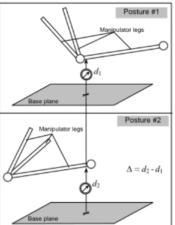
To identify the model parameters, we propose a sin-gle-sensor measurement techniques for the leg/surface parallelism (Fig. 2). It is based on fixed location of the measuring device for two distinct leg postures corresponding to the minimum/maximum of the joint coordinates. Relevant calibration experi-ment consists of the following steps:
Step 1. Move the manipulator to the “mechanical zero”; locate two gauges in the middle of the X-leg
(parallel to the axes Y and Z); get their readings.
Step 2. Move the manipulator to the “X-maximum”
and “X-minimum” postures, get the gauge readings, and compute differences Δy+x,Δz+x,Δyx−,Δz−x.
Step 3+. Repeat steps 1, 2 for the Y- and Z-legs and
compute corresponding differences.
Manipulator legs d1 Δ = d2 -d1 Manipulator legs d2 Base plane Base plane Posture #1 Posture #2
Fig. 2. Measuring the leg/surface parallelism
3.2 Calibration equations
The calibration equations can be derived using ex-pressions from sub-section 2.5. First, it is required to define the gauge initial location. For the X-leg, it is the midpoint of the line segment bounded by the TCP (Δρx, Δρy, Δρz) and the centre of the X- joint
(L+Δρx, 0, 0). This yields the following expression
for the X-leg midpoint: (L 2+ Δρx; Δρy 2; Δρz 2). For the “X-maximum” posture, the X-leg location is also defined by same two points, but their coordi-nates are (LSα+Δρx;TαΔρx+Δρy;TαΔρx+Δρz) and
) 0 ; 0 ;
(L+LSα+Δρx respectively. Then, it may be written the equations of a straight-line passing along the X-leg and computed the point corresponding to
x
L
x= 2+Δρ . Hence, finally, the deviations of the X-leg measurements may be expressed as
z x x y x x S T S z S T S y ρ Δ + ρ Δ + = Δ ρ Δ + ρ Δ + = Δ α α α + α α α + ) 5 . 0 ( ; ) 5 . 0 ( (7) Similar approach may be applied to the “X-minimum” posture, as well as to the equivalent post-ures for the Y- and Z-legs. This gives the system of twelve linear equations in three unknowns
⎥ ⎥ ⎥ ⎥ ⎥ ⎥ ⎥ ⎥ ⎥ ⎥ ⎥ ⎥ ⎥ ⎥ ⎥ ⎥ ⎥ ⎦ ⎤ ⎢ ⎢ ⎢ ⎢ ⎢ ⎢ ⎢ ⎢ ⎢ ⎢ ⎢ ⎢ ⎢ ⎢ ⎢ ⎢ ⎢ ⎣ ⎡ Δ Δ Δ Δ Δ Δ Δ Δ Δ Δ Δ Δ = ⎥ ⎥ ⎦ ⎤ ⎢ ⎢ ⎣ ⎡ ρ Δ ρ Δρ Δ ⋅ ⎥ ⎥ ⎥ ⎥ ⎥ ⎥ ⎥ ⎥ ⎥ ⎥ ⎥ ⎥ ⎥ ⎦ ⎤ ⎢ ⎢ ⎢ ⎢ ⎢ ⎢ ⎢ ⎢ ⎢ ⎢ ⎢ ⎢ ⎢ ⎣ ⎡ − − + + − − + + + − + + x z x z y z y z x y x y z y x z x z x z y z y y x y x b c c b b c c b b c c b b c c b b c c b b c c b 2 2 2 2 1 1 1 1 2 2 2 2 1 1 1 1 2 2 2 2 1 1 1 1 0 0 0 0 0 0 0 0 0 0 0 0 (8)
where bi =sinαi; ci =(0.5 sin+ αi) tanαi and the angles α1, α2 are computed for the maximum and
minimum postures respectively. The reduced version of this system may be obtained if to assess the leg/plane parallelism by the difference between the “maximum” and “minimum” postures. The latter leads to the system of six linear equations in three unknowns.
4. EXPERIMENTAL RESULTS
3.1 Experimental setup
The measuring system is composed of standard com-parator indicators attached to the universal magnetic stands allowing fixing them on the manipulator bases. The indicators have resolution of 10 μm and are sequentially used for measuring the X-, Y-, and Z-leg parallelism while the manipulator moves be-tween the Max, Min and Zero postures. For each measurement, the indicators are located on the me-chanism base in such manner that a corresponding leg is admissible for the gauge contact for all inter-mediate posters (Fig. 3).
For each leg, the measurements were repeated three times for the following sequence of motions: Ze-ro → Max → Min → ZeZe-ro→ …. Then, the results were averaged and used for the parameter identifica-tion. It should be noted that measurements demon-strated very high repeatability (about 0.02 mm).
4.2 Calibration results
The first calibration experiment produced rather high parallelism deviation, up to 2.37 mm, which in the frames of the adopted kinematic model was expected to be reduced down to 1.07 mm only (Table 1). The corresponding residual norm was also rather high and yielded unrealistic estimate of the measurement noise parameter σ ≈ 1.0 mm. It impels to conclude that the mechanism mechanics requires more careful tuning. Consequently, the location of the joint axes was adjusted mechanically to ensure the leg paral-lelism for the Zero posture.
Fig. 3. Experimental Setup
The second calibration experiment (after mechanical tuning) yielded lower parallelism deviations, less than 0.70 mm. For these data, the developed calibra-tion algorithm yielded the joint offsets that are ex-pected to reduce the deviation down to 0.28 mm. Besides, the estimated value of σ ≈ 0.28 mm is rather realistic taking into account both the measurement accuracy and the manufacturing/assembling toler-ances. Accordingly, the identified vales of the joint offsets were input into the control software.
The third experiment (validation of the identified parameters) demonstrated good agreement with the expected results. In particular, the maximum paral-lelism deviation reduced down to 0.34 mm (expected 0.28 mm), while its root-mean-square decreased down to 0.21 mm (expected 0.20 mm). On the other hand, further adjusting of the kinematic model to the new experimental data gives both negligible im-provement of the r.m.s. and rather small alteration of the model parameters. It is evident that further reduc-tion of the parallelism deviareduc-tion is bounded by the manufacturing and assembling errors.
Hence, the calibration results confirm validity of the proposed identification technique and its ability to tune the joint offsets from observations of the leg parallelism.
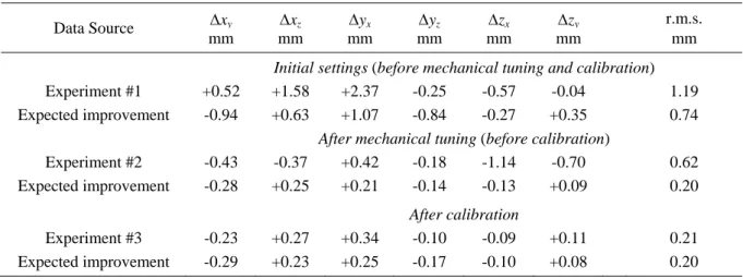
Table 1. Experimental data and expected improvements of accuracy (model-based)
Data Source Δxy Δxz Δyx Δyz Δzx Δzy r.m.s.
mm mm mm mm mm mm mm
Initial settings (before mechanical tuning and calibration)
Experiment #1 +0.52 +1.58 +2.37 -0.25 -0.57 -0.04 1.19 Expected improvement -0.94 +0.63 +1.07 -0.84 -0.27 +0.35 0.74
After mechanical tuning (before calibration)
Experiment #2 -0.43 -0.37 +0.42 -0.18 -1.14 -0.70 0.62 Expected improvement -0.28 +0.25 +0.21 -0.14 -0.13 +0.09 0.20
After calibration
Experiment #3 -0.23 +0.27 +0.34 -0.10 -0.09 +0.11 0.21 Expected improvement -0.29 +0.23 +0.25 -0.17 -0.10 +0.08 0.20
5. CONCLUSIONS
This paper proposes a novel calibration approach for the parallel manipulators, which is based on observa-tions of manipulator leg parallelism with respect to some predefined planes. Presented for the Orthog-lide-type mechanisms, this approach may be also applied to other manipulator architectures that admit parallel leg motions along the longitudinal axis. The proposed calibration technique employs a simple and low-cost measuring system composed of stan-dard comparator indicators attached to the universal magnetic stands. They are sequentially used for mea-suring the deviation of the relevant leg location while the manipulator moves the TCP along the Cartesian axes. From the measured differences, the calibration algorithm estimates the joint offsets that are treated as the most essential parameters to be tuned. The validity of the proposed approach and efficiency of the developed numerical algorithm were confirmed by the calibration experiments with the Orthoglide prototype, which allowed reducing the residual r.m.s. by three times.
To increase the calibration precision, future work will focus on the development of the specific assem-bling fixture ensuring proper location of the linear actuators and also on the essential theoretical issues such as calibration experiment planning, expanding the set of the identified model parameters and their identifiably analysis, and compensation of the non-geometric errors non detected within the frames of the adopted kinematic model.
REFERENCES
Caro, S., Ph. Wenger, F. Bennis, and D. Chablat (2006). Sensitivity Analysis of the Orthoglide, a 3-DOF Translational Parallel Kinematic Ma-chine, ASME Journal of Mechanical Design (in print).
Chablat, D. and Ph. Wenger (2003). Architecture Optimization of a 3-DOF Parallel Mechanism for Machining Applications, the Orthoglide,
IEEE Transactions On Robotics and Automa-tion, Vol. 19 (3), pp. 403-410.
Huang, T., D.G. Chetwynd, D.J. Whitehouse, and J. Wang (2005). A general and novel approach
for parameter identification of 6-dof parallel ki-nematic machines. Mechanism and Machine
Theory, Vol. 40 (2), pp. 219-239.
Innocenti, C. (1995). Algorithms for kinematic cali-bration of fully-parallel manipulators. In:
Com-putational Kinematics, Kluwer Academic
Pub-lishers, pp. 241-250.
Iurascu, C.C. and F.C. Park (2003). Geometric algo-rithm for kinematic calibration of robots contain-ing closed loops. ASME Journal of Mechanical
Design, Vol. 125(1), pp. 23-32.
Jeong J., D. Kang, Y.M. Cho, and J. Kim (2004). Kinematic calibration of redundantly actuated parallel mechanisms. ASME Journal of
Mechan-ical Design, Vol. 126 (2), pp. 307-318.
Merlet, J.-P. (2000). Parallel Robots, Kluwer Aca-demic Publishers, Dordrecht, 2000.
Pashkevich A., Wenger P. and Chablat D. (2005). Design Strategies for the Geometric Synthesis of Orthoglide-type Mechanisms. Journal of
Me-chanism and Machine Theory, Vol. 40 (8), pp.
907-930.
Renaud, P., N. Andreff, F. Pierrot and P. Martinet (2004). Combining end-effector and legs obser-vation for kinematic calibration of parallel me-chanisms. IEEE International Conference on
Robotics and Automation (ICRA’2004),
New-Orleans, USA, pp. 4116-4121.
Renaud, P., N. Andreff, G. Gogu and P. Martinet (2006). Kinematic calibration of parallel me-chanisms: a novel approach using legs observa-tion, IEEE Transactions on Robotics (in print). Tlusty, J., J.C. Ziegert and S. Ridgeway (1999).
Fundamental Comparison of the Use of Serial and Parallel Kinematics for Machine Tools.
CIRP Annals, Vol. 48 (1), pp. 351-356.
Tsai, L.W. (1999). Robot Analysis: the Mechanics of
Serial and Parallel Manipulators; John Wiley &
Sons, New York.
Wang, J. and O. Masory (1993). On the accuracy of a Stewart platform - Part I: The effect of manufac-turing tolerances. IEEE International
Confe-rence on Robotics and Automation (ICRA’93),
Atlanta, Georgia, pp. 114–120.
Wenger, P., C. Gosselin and B. Maille (1999). A comparative study of serial and parallel mechan-ism topologies for machine tools. In: