UNIVERSITÉ DE MONTRÉAL
DEVELOPMENT OF POLYMER NANOCOMPOSITES FROM RENEWABLE CELLULOSE NANOCRYSTALS
DAVOOD BAGHERIASL
DÉPARTEMENT DE GÉNIE CHIMIQUE ÉCOLE POLYTECHNIQUE DE MONTRÉAL
THÈSE PRÉSENTÉE EN VUE DE L’OBTENTION DU DIPLÔME DE PHILOSOPHIAE DOCTOR
(GÉNIE CHIMIQUE) JANVIER 2016
UNIVERSITÉ DE MONTRÉAL
ÉCOLE POLYTECHNIQUE DE MONTRÉAL
Cette thèse intitulée:
DEVELOPMENT OF POLYMER NANOCOMPOSITES FROM RENEWABLE CELLULOSE NANOCRYSTALS
présentée par : BAGHERIASL Davood
en vue de l’obtention du diplôme de : Philosophiae Doctor a été dûment acceptée par le jury d’examen constitué de : M. TAVARES Jason-Robert., Ph. D., président
M. CARREAU Pierre, Ph. D., membre et directeur de recherche M. DUBOIS Charles, Ph. D., membre et codirecteur de recherche M. RIEDL Bernard, Ph. D., membre et codirecteur de recherche M. AJJI Abdellah, Ph. D., membre
DEDICATION
ACKNOWLEDGEMENTS
I would like to express my deep gratitude to my supervisor, Professor Pierre J. Carreau, and my co-supervisors, Professors Charles Dubois and Bernard Riedl. Success of this project was impossible without their extensive supports, encouragements, knowledge, patience and experiences.
Besides my supervisors, I would like to thank the rest of my thesis committee, namely Professor Abdellah Ajji, Professor Michel Huneault and Professor Jason-Robert Tavares for accepting to evaluate my thesis.
A sincere appreciation goes to Professor Marie-Claude Heuzey and Dr. Wadood Y. Hamad, and all the student members of the Rheology Group who have generously shared their knowledge and experiences with me during the productive discussions.
I acknowledge the help and kind cooperation of technical and administrative staffs of Chemical Engineering Department of Polytechnique Montréal during my PhD, especially Mélina Hamdine, Guillaume Lessard, Martine Lamarche, Gino Robin and Valerie Baudart.
I would like to thank Mrs. Mounia Arkoun for her kind help in translating abstract of this thesis to French.
I would like to thank Professor Hossein Nazockdast, my supervisor in Amirkabir University of Technology (Tehran Polytechnic), who taught me great scientific and life lessons.
I would like to convey my heartfelt thanks to all my friends and colleagues who have supported and helped me during my PhD studies and my life in Montréal.
Definitely, my accomplishments throughout my life would not have been possible without unconditional love and support of my beloved parents and brothers.
Finally, my deepest gratitude goes to my lovely spouse, Fatemeh. There will never be a right word to express my feeling of appreciation for everything she has done. With all my heart, I would like to express my undying gratitude and love to her for the overwhelming support she has provided and for sacrifices she has made throughout the past eight years of my life. Thank you for being my best friend. I owe you everything.
RÉSUMÉ
L'utilisation de la cellulose nanocristalline (CNC) comme agent de renfort dans les polymères est en croissance; toutefois, cela reste limité à quelques polymères hydrosolubles ou sous forme de latex. La plupart des polymères industriels communs étant insolubles dans l'eau, par conséquent, la CNC hydrophile ne peut être dispersée dans des matrices polymères hydrophobes. Une compatibilisation ou une modification de surface sont donc nécessaires pour obtenir une bonne dispersion et, de ce fait, améliorer les propriétés des polymères.
Dans ce projet de recherche, notre objectif était de développer des nanocomposites polymère-CNC avec une structure bien dispersée et des propriétés améliorées, comparativement aux polymères non modifiés ou avec de faibles charges de CNC. À cet effet, nous avons choisi le polypropylène (PP), une des polyoléfines les plus communément utilisées dans l'industrie, et le polylactide (PLA), le biopolymère ayant suscité le plus d’intérêt dans l'industrie. Par conséquent, notre étude a été divisée en deux grandes parties.
La première phase du projet portait sur le développement des nanocomposites PP-CNC. Pour favoriser une meilleure dispersion et mouillage des CNC hydrophiles dans la matrice de PP hydrophobe, un poly(éthylène-co-vinyle alcool) a été utilisé comme compatibilisant via une méthode de préparation d’un mélange maître (masterbatch). Deux mélanges maîtres différents ont été préparés, l’un en solution et l'autre à l'état fondu, avec un rapport CNC/compatibilisant de 1/3. Les nanocomposites ont été ensuite préparés par homogénéisation à l'état fondu des mélanges maîtres avec le PP, et avec une teneur en CNC de 5% en poids. Un mélangeur interne a été utilisé à cet effet. Pour des fins de comparaison, du PP contenant 15% en poids d'agent compatibilisant et du PP contenant 5% en poids de CNC ont également été préparés par mélange direct à l'état fondu.
Par la suite, l'effet de la CNC sur les propriétés rhéologiques, mécaniques et thermiques du PP a été étudié. Les observations en microscopie électronique à balayage ont montré la disparition de gros agglomérats après ajout du compatibilisant. La viscosité complexe et le module de conservation des échantillons nanocomposites compatibilisés et obtenus avec la méthode en solution ont été augmentés à basses fréquences, comparativement aux nanocomposites non compatibilisés. De plus, un maximum suivi d’une décroissance (overshoot) prononcé de la viscosité transitoire, dans un test de croissance de la contrainte en cisaillement a été observé pour
le nanocomposite compatibilisé. Le module d'Young a augmenté jusqu'à près de 47% par rapport au PP seul; la résistance à la rupture en traction est restée inchangée et l’allongement à la rupture a diminué pour le nanocomposite compatibilisé. Le module de conservation du PP à température ambiante dans une analyse thermique mécanique dynamique (DMTA) a augmenté jusqu'à près de 60%, quand une bonne dispersion a été atteinte en utilisant l'agent compatibilisant. L'effet de nucléation de la CNC sur la cristallisation du PP a été confirmé par l’augmentation de la cristallinité du nanocomposite PP et par l’augmentation de la température de cristallisation après l’ajout du compatibilisant. Ces observations ont été attribuées à l'efficacité du poly(éthylène-co-vinyle alcool) comme un agent de compatibilisation et ce, en particulier lorsque le mélange maître a été préparé en solution.
La deuxième phase du projet a focalisé sur le développement de bio-nanocomposites PLA-CNC à haute performance. Une simple et nouvelle méthode de coulée utilisant un solvant polaire (N,N-diméthylformamide) a été utilisée pour favoriser une bonne dispersion de la CNC hydrophile dans une matrice PLA à différentes charges de CNC, sans toutefois la nécessité de modifier la CNC ni d’utiliser un compatibilisant. Par la suite, l'effet de la CNC sur les propriétés du PLA a été étudié à l’état fondu et à l’état solide. La microscopie électronique à transmission a révélé l'existence d'une structure bien dispersée de la CNC dans la matrice de PLA. La viscosité complexe et les modules de conservation et de perte ont augmenté de manière significative par l'incorporation de 1% en poids et plus de CNC, en particulier à basses fréquences. Ces améliorations ont été attribuées à la formation d'un réseau interconnecté de la CNC dans la matrice PLA. Le seuil de percolation rhéologique a été établi à 0,68% en poids de CNC. En outre, la viscosité en régime permanent, la contrainte de cisaillement et la première différence des contraintes normales ont augmentés. Le seuil apparent des contraintes a également augmenté avec la teneur en CNC, aussi bien en SAOS qu’en cisaillement en régime permanent. La règle de Cox-Merz n’était pas valable pour les nanocomposites PLA-CNC; Toutefois, pour les nanocomposites à contenu élevé en CNC, la règle de Cox-Merz étendue était applicable. Des maxima prononcés suivis d’une décroissance (overshoots) ont été observés en cisaillement transitoire et pour des écoulements dans un sens et le sens inverse. Ces maxima suivis d’une décroissance (overshoots) ainsi que la reprise de structure suite à des pré-cisaillements ont été expliqués par la formation d’un réseau et par le rôle important du mouvement Brownien pour
rétablir la structure. Les nanocomposites moins concentrés pré-cisaillés à des taux plus élevés ont nécessité des temps plus longs pour rétablir leur structure initiale, après l’arrêt du cisaillement. Les propriétés rhéologiques ont démontré l'efficacité de la sonication pour disperser la CNC et par conséquent, pour former un réseau interconnecté de CNC dans la matrice PLA. Le module d'Young des nanocomposites a augmenté jusqu'à environ 23% comparativement au PLA seul; cependant, la déformation à la rupture a légèrement diminué et la contrainte en traction quant à elle est demeurée inchangée. En DMTA, le module de conservation des nanocomposites PLA-CNC a augmenté jusqu'à près de 74% dans la région vitreuse et jusqu'à près de 490% dans la région caoutchoutique. L’augmentation de la cristallinité du PLA dans les nanocomposites et le déplacement de la température de cristallisation vers des valeurs plus élevées ont été attribués à l'effet de nucléation de la CNC sur la cristallisation du PLA.
A notre connaissance, il s’agit de la première fois qu’une aussi bonne dispersion de la CNC dans un polymère non hydrosoluble est obtenue et que de telles améliorations dans les propriétés des nanocomposites à l'état solide et fondu sont atteintes, sans aucun changement dans la structure morphologique de la CNC ou l'utilisation de compatibilisants. En outre, au meilleur de notre connaissance, ceci est la première étude fondamentale du comportement rhéologique des nanocomposites PLA-CNC dans différents modes d'écoulement en cisaillement.
ABSTRACT
The application of cellulose nanocrystals (CNCs) as reinforcing agents in polymers have grown, but limited to a few water-soluble polymers or polymers in latex form. However, most of the common polymers in industry are non water-soluble. Therefore, the hydrophilic CNCs cannot be dispersed in hydrophobic polymer matrices and surface modification or compatibilization are necessary to achieve a good dispersion and, consequently, to enhance the properties of polymers. In this research project our objective was to develop polymer-CNC nanocomposites with a dispersed structure and enhanced properties, relative to the neat polymers, at low CNC loadings. To this end, we selected as matrices polypropylene (PP), which is one the most commonly polyolefins, and polylactide (PLA), which has attracted the largest interest among the biopolymers in industry. The research project was conducted in two phases.
The first phase of the project dealt with the development of the PP-CNC nanocomposite. To favor a better dispersion and wetting of hydrophilic CNCs within the hydrophobic PP matrix a poly(ethylene-co-vinyl alcohol) was used as a compatibilizer via a masterbatch preparation method. Two different masterbatches were prepared, one in solution and the other in molten state, with the CNC to compatibilizer ratio of 1/3. Then, the nanocomposites were prepared by melt-mixing of the masterbatches with PP using an internal mixer at a CNC content of 5 wt%. For sake of comparison, PP containing 15 wt% compatibilizer and PP containing 5 wt% CNCs were also prepared via direct melt mixing. Then, the effect of the CNCs on the rheological, mechanical and thermal properties of PP was investigated. Scanning electron microscopy showed the disappearance of large agglomerates when the compatibilizer was employed. The complex viscosity and storage modulus of the nanocomposite sample containing the compatibilizer prepared by a solution method were increased at low frequencies, compared to those of the non-compatibilized nanocomposite samples. Moreover, a pronounced overshoot for the transient viscosity in a shear stress growth experiment was observed for the compatibilized nanocomposite. The Young modulus was enhanced, up to ca. 47 % compared to the neat PP; the tensile strength remained unchanged and strain at break was decreased for the compatibilized nanocomposite. The storage modulus of the PP at room temperature in dynamic mechanical thermal analysis (DMTA) was increased up to ca. 60% when a good state of dispersion was achieved using the compatibilizer. The nucleation effect of the CNCs on the crystallization of the
PP was confirmed by the enhanced crystalline content of the PP nanocomposites and increased crystallization temperature using the compatibilizer. These observations were ascribed to the efficiency of the poly(ethylene-co-vinyl alcohol) as a compatibilizer, especially when the masterbatch was prepared in solution.
The second phase focused on the development of high performance PLA-CNC bionanocomposites. A simple and novel solution casting method with a polar solvent (i.e. N,N-dimethylformamide) was used to favor a good dispersion of hydrophilic CNCs within a PLA matrix at different CNC loadings without the need of CNC modification or use of any compatibilizer. Then, the effect of the CNCs on the properties of the PLA for both molten and solid states was investigated. Transmission electron microscopy revealed the existence of well-dispersed structure of CNCs within the PLA matrix. The complex viscosity and the storage and loss moduli were increased significantly, especially at low frequencies, by the incorporation of 1 wt% CNCs and larger contents. These enhancements were ascribed to the formation of an interconnected network of CNCs within the PLA matrix. The rheological percolation threshold was determined to be 0.68 wt% CNC. Furthermore, the steady-state viscosity, shear stress and first normal stress difference were increased. The apparent yield stress increased with CNC content, for both SAOS and steady-shear experiments. The Cox-Merz rule was not valid for the PLA-CNC nanocomposites; however, for nanocomposites at large CNC contents the extended Cox-Merz rule was applicable. Pronounced overshoots in transient shear for forward and reverse flows and the structure build-up of samples after pre-shearing were explained by a network formation and the important role of the Brownian motion for structure recovery. The less concentrated nanocomposites pre-sheared at larger rates needed longer times after the cessation of the shear flow to recover their initial structure.
The rheological properties demonstrated the efficiency of the sonicator in solution mixing to disperse the CNCs with the consequent formation of an interconnected network of CNCs within the PLA matrix. The Young modulus of the nanocomposites increased up to ca. 23% compared to the neat PLA; however, the strain at break slightly decreased and tensile strength remained unchanged. In DMTA, the storage modulus of the PLA-CNC naonocomposites increased up to ca. 74% in glassy region and up to ca. 490% in the rubbery region. The observation of increased crystalline content of the PLA in the nanocomposites and shift in the crystallization temperature
towards higher temperatures, were attributed to the nucleation effect of the CNCs on the crystallization of PLA.
To our knowledge, this is the first time that a very good dispersion of CNCs in a non-hydrosoluble polymer together with huge increases in the properties of the corresponding solid and molten state nanocomposite is achieved, without any change in the morphological structure of the CNCs or use of any compatibilizer. Moreover, to the best of our knowledge, this is the first systematic investigation of the rheological behavior of PLA-CNC nanocomposites in different shear flow fields.
TABLE OF CONTENTS
DEDICATION ... III ACKNOWLEDGEMENTS ... IV RÉSUMÉ ... V ABSTRACT ... VIII TABLE OF CONTENTS ... XI LIST OF TABLES ... XV LIST OF FIGURES ... XVICHAPTER 1 INTRODUCTION ... 1
CHAPTER 2 LITERATURE REVIEW ... 3
2.1 Overview ... 3
2.2 CNCs: Preparation and Structure ... 3
2.3 Polylactide (PLA) ... 5 2.3.1 PLA structure ... 5 2.4 Polypropylene (PP) ... 7 2.5 CNC Treatments ... 8 2.6 PP-CNC (nano)composites ... 10 2.7 PLA-CNC (nano)composites ... 19
2.8 Rheological behavior of polymer nanocomposites ... 25
2.8.1 SAOS ... 26
2.8.2 Steady-shear tests ... 27
2.8.3 Transient tests ... 28
2.8.4 Structure build-up tests ... 29
CHAPTER 3 OBJECTIVES ... 32
CHAPTER 4 ORGANIZATION OF THE ARTICLES ... 33
CHAPTER 5 ARTICLE 1 : PROPERTIES OF POLYPROPYLENE AND POLYPROPYLENE/POLY(ETHYLENE-CO-VINYL ALCOHOL) BLEND/CNC NANOCOMPOSITES ... 34 5.1 Introduction ... 35 5.2 Experimental ... 37 5.2.1 Materials ... 37 5.2.2 Sample preparation ... 38 5.2.3 Characterization ... 38
5.3 Results and discussion ... 39
5.3.1 SEM analysis ... 39
5.3.2 Rheology ... 40
5.3.3 Mechanical and thermal properties ... 42
5.4 Conclusion ... 47
5.5 Acknowledgments ... 47
5.6 Supplementary Information ... 48
5.7 References ... 49
CHAPTER 6 ARTICLE 2 : SHEAR RHEOLOGY OF POLYLACTIDE (PLA)-CELLULOSE NANOCRYSTAL (CNC) NANOCOMPOSITES ... 54
6.1 Introduction ... 55
6.2 Experimental Section ... 57
6.2.1 Materials ... 57
6.2.2 Sample Preparation ... 57
6.3 Results and discussion ... 59 6.3.1 Microscopy ... 59 6.3.2 Rheology ... 60 6.4 Concluding remarks ... 71 6.5 Acknowledgments ... 72 6.6 References ... 72
CHAPTER 7 ARTICLE 3 : ENHANCED PROPERTIES OF POLYLACTIDE BY INCORPORATING CELLULOSE NANOCRYSTALS ... 77
7.1 Introduction ... 78
7.2 Experimental Section ... 80
7.2.1 Materials ... 80
7.2.2 Sample Preparation ... 80
7.2.3 Characterization ... 81
7.3 Results and discussion ... 82
7.3.1 Microscopy ... 82
7.3.2 Rheology ... 84
7.3.3 Mechanical and thermal properties ... 85
7.4 Concluding remarks ... 91
7.5 Acknowledgments ... 91
7.6 References ... 91
CHAPTER 8 GENERAL DISCUSSION ... 97
CHAPTER 9 CONCLUSIONS AND RECOMMENDATIONS... 100
9.1 Conclusions ... 100
9.2 Original Contributions ... 101
LIST OF REFERENCES ... 104
LIST OF TABLES
Table 2.1: Dimensions of cellulose nanocrystals from various sources obtained by different techniques (adapted from Ref. [17]) ... 4 Table 2.2: Effects of stereochemistry and annealing on mechanical properties of polylactides (adapted from Ref. [23]) ... 7 Table 2.3: Tensile properties of neat PP, PP and PP-g-MA blends, and filled blends (adapted from Ref. [41]) ... 15 Table 2.4: Young modulus of the samples prepared with different compatibilizers and CNC to compatibilizer ratios. The concentration of CNC is fixed at 1 wt% (adapted from Ref. [42]) ... 16 Table 2.5: Thermal parameters of PLLA and PLLA containing partially silylated (SCNCs) and unmodified CNCs with final concentrations of 1 and 2 wt%. Data derived from the heating DSC scans (adapted from Ref. [45]) ... 23 Table 2.6: Tensile properties of PLLA and PLLA-CNC composite films at room temperature (adapted from Ref. [45]) ... 23 Table 2.7: Tensile properties of PLA and PLA containing surface modified (s-CNCs) and unmodified CNCs. The numbers in the formulation represent the concentration of CNCs in the systems, namely 1 and 3 wt% (adapted from Ref. [46]) ... 23 Table 2.8: Storage modulus, E’, of annealed PLA and PLA filled with silane-surface modified CNCs (adapted from Ref. [13]) ... 24 Table 6.1: Yield stress and melt flow index of the nanocomposites using the Herschel-Bulkley model (Eq. 6.4) and the modified Herschel-Bulkley model (Eqs. 6.1 and 6.2) ... 64
LIST OF FIGURES
Figure 2.1: Cellulose from plants to molecular structure (from Ref. [20]) ... 5 Figure 2.2: Stereoisomers of lactide (from Ref. [22]) ... 6 Figure 2.3: Different types of polylactides (from Ref. [22]) ... 7 Figure 2.4: Schematic of the polymerization of polypropylene from propylene monomer in the presence of catalyst (from Ref. [24]) ... 8 Figure 2.5: Different tacticities of polypropylene. R indicates methyl groups ... 8 Figure 2.6: SEM micrographs of aPP composite films reinforced with 6 wt % (a) surface modified CNCs (SUCNC), (b) compatibilized CNCs (GRCNC), and (c) unmodified CNCs (AGCNC) (from Ref. [39]) ... 11 Figure 2.7: Storage modulus vs temperature from DMTA tests comparing (a) neat aPP and (b) neat iPP with composites reinforced with 6 wt% unmodified CNCs (AGCNC), surface modified CNCs (SUCNC), and compatibilized CNCs (GRCNC) (adapted from Ref. [39, 40]) ... 12 Figure 2.8: Stress vs strain curves for (a) neat aPP and (b) neat iPP and composites reinforced with 6 wt% AGCNC, SUCNC, and GRCNC (adapted from Ref. [39, 40]) ... 12 Figure 2.9: Tensile strength of: (a) neat PP, PP with 0.8 wt% MA, and PP with 2 wt%
PP-g-MA; (b) PP-PP-g-MA blend with 0.8 wt% PP-g-MA and different CNC contents (from Ref. [41]) ... 15 Figure 2.10: SEM images of: (a) spray-freeze dried CNC obtained from 1 wt% CNC aqueous suspension (CNCSFD1), (b) spray-freeze dried CNC obtained from 2 wt% CNC aqueous suspension (CNCSFD), (c, e) PP containing 5 wt% CNCSFD1 and (d, f) PP containing 5 wt% CNCSFD2 at (c, d) low and (e, f) high magnification (from Ref. [43]) ... 16 Figure 2.11: Plots of (a,b) complex viscosity vs angular frequency for (a) PP, PP with 5 wt% spray-dried (CNCSD) and freeze-dried (CNCFD) CNC, and (b) PP and PP containing CNCSFD1 agglomerates, and (c) storage and loss moduli vs angular frequency of samples. The insets show SEM images of dried (CNCSD), freeze-dried (CNCFD), and spray-freeze-dried (CNCSFD) CNC agglomerates (adapted from Ref. [43]) ... 18
Figure 2.12: Storage modulus vs temperature for PP and PP containing 5 wt% CNCSD, CNCSFD1, and CNCSFD2 (from Ref. [43]) ... 19 Figure 2.13: SEM micrographs of PLA containing 7 wt% of (a) spray dried CNC (CNCSD) and spray-freeze dried CNC (CNCSFD) (Scale bars: 10 μm) (from Ref. [44]) ... 20 Figure 2.14: Complex viscosity, storage and loss moduli vs frequency for PLA and PLA-CNC nanocomposites. The initial concentration of CNC in the aqueous suspensions was 3 wt% prior to spray-freeze drying (adapted from Ref. [44]) ... 21 Figure 2.15: The DMTA data for neat PLA and PLA-CNC nanocomposites with 1.5, 3 and 7 wt% spray-freeze dried CNCs: (a) storage modulus and (b) tan δ vs temperature (from Ref. [44]) ... 21 Figure 2.16: DSC runs in cooling cycles for PLLA and PLLA containing partially silylated (SCNC) and unmodified CNCs with final concentration of 1 and 2 wt% (from Ref. [45]) .. 22 Figure 2.17: Effect of PEO as a compatibilizer on CNC dispersion in a PLA matrix: (a)
PLA-CNC prepared via direct melt mixing (scale bar: 10 μm), (b) and (c) PLA containing PEO-CNC masterbatch with high molecular weight PEO and PEO/PEO-CNC: 0.25 and 1 (scale bars: 10 (a,b) and 1 μm for (c)), respectively. All samples contain 3 wt% CNC (adapted from Ref. [47]) ... 25 Figure 2.18: Plots of the complex viscosity vs complex modulus for polycarbonate-CNT nanocomposites at 230 °C (from Ref. [48]) ... 27 Figure 2.19: Storage modulus as a function of the nanotube loading for PC-CNT nanocomposites at 230 °C (1 rad.s-1 data). The line is a fit with the power-law expression (Eq. 2-2) (from
Ref. [48]) ... 27 Figure 2.20: Steady-shear viscosity for EVA28-nanoclay nanocomposites as a function of shear rate at 130 °C (from Ref. [50]) ... 28 Figure 2.21: (a) Shear stress growth as a function of strain for PP/PP-g-MA/Cloisite 20A (80/15/5) at T = 180 °C and shear rate of 0.1 s-1 for: (a) repeated forward flow tests and (b)
reverse flow tests after various rest times. The rest times of the legend correspond to those for the reverse transient experiments (adapted from Ref. [51]) ... 29
Figure 2.22: Structure changes under preconditioning: (a) steady viscosity vs shear rate and (b) evolution of the storage modulus in time sweep tests at a frequency of 125.6 rad.s−1 right
after cessation of the steady-shear test carried out in (a). Symbols correspond to the values of the initial shear rates (from Ref. [52]) ... 30 Figure 5.1: SEM micrographs of two different locations of PP/5CNC (a) and (b), and PP/15SCO/5CNC (c) and (d) ... 40 Figure 5.2: Complex viscosity (a) and storage modulus (b) versus frequency of the neat PP, PP containing 15 wt% compatibilizer and nanocomposites in SAOS at 195 °C (strain = 5 %) . 41 Figure 5.3: Variations of the transient viscosity with time for a shear stress growth experiment at = 0.02 s−1 and T = 195 °C ... 42 Figure 5.4: Comparison of the tensile properties: Young modulus (a), tensile strength (b) and tensile strain at break (c) of the samples. The numbers above the bars represent the changes in percent with respect to the neat PP ... 43 Figure 5.5: DMTA data for the various samples over a large range of temperature, from −70 to 140 °C: (a) tan δ (the numbers in the legend of the figure represent the area under the Tg
peak observed for each sample divided by that of the neat PP); (b) storage modulus ... 45 Figure 5.6: Crystalline content of the samples (a), calculated based on the data obtained in the heating cycle using Eq. 1, and comparison of on-set temperature of the crystallization peak of the samples (b), occurring in the cooling cycle ... 46 Figure 6.1: TEM image of CNCs taken from an aqueous suspension of 0.5 wt% CNC (a), SEM micrograph (b), and TEM images (c) and (d) of PLA4CNC from two different locations of the sample ... 60 Figure 6.2: Complex viscosity, η* (a) and storage modulus, G' (b) vs frequency,, of the neat PLA and PLA-CNC nanocomposites at 170 °C (strain = 5%) ... 61 Figure 6.3: Comparison of η* (a) and G (b) vs of PLA2CNC prepared via solution (S) and melt (M) method ... 62 Figure 6.4: Complex viscosity, η*, vs the complex modulus, G*, of the neat PLA and PLA-CNC nanocomposites. The lines are the fits of the modified Herschel-Bulkley model (Eq. 6.1) .. 63
Figure 6.5: Storage modulus of the PLA-CNC nanocomposites as a function of the CNC loading obtained at 170 °C and = 0.1 rad.s-1. The line is a fit with the power-law expression of Eq.
6.3. Note that the value of the neat PLA was obtained after extrapolation to = 0.1 rad.s-1 65
Figure 6.6: Variation of the steady-state viscosity vs shear rate of the neat PLA and nanocomposite samples; (a) filled symbols represent the experiments performed from high-to-low shear rates while the open symbols show the results of measurements from low-to-high on the same samples. (b) The two consecutive experiments were both conducted from high-to-low shear rates; open symbols: first test: filled symbols, second test ... 66 Figure 6.7: Steady-state stress data for the PLA-CNC nanocomposites from high-to-low shear rate measurements; (a) Shear stress vs shear rate. The lines are fits of the Herschel-Bulkley model (Eq. 6.4). (b) First normal stress difference vs shear rate ... 67 Figure 6.8: Variation of the steady-state and complex viscosities of the neat PLA and nanocomposite samples versus (a) shear rate and frequency, and (b) shear rate and 𝛾0𝜔, respectively ... 68 Figure 6.9: Variations of the shear stress growth coefficient,, of the PLA and PLA-CNC nanocomposites as functions of time for an imposed shear rate 𝛾 = 5 s-1 in forward (a) and
reversed flow after 0, 200 and 1000 s (b) ... 69 Figure 6.10: Structure evolution of PLA-CNC nanocomposites with time right after the cessation of shear flow at 𝛾 = 5 s-1 (a) (the inset shows a magnified part of Fig. 10a); structure
development of the PLA4CNC nanocomposite sample not pre-sheared and pre-sheared at 𝛾 of 0.05, 0.5 and 5 s-1 (b). G measured at a frequency of 1 rad.s-1 and fits using Eq. 6 (dashed lines) ... 71 Figure 7.1: TEM image of CNC aqueous suspension (0.5 wt%) (a), SEM micrograph (b) and TEM image (c) of PLA4CNC ... 83 Figure 7.2: SAOS data for the neat PLA and PLA-CNC nanocomposites at 170 °C (strain = 0.05): 𝐺˝, filled symbols, and 𝐺′, open symbols, (a) and tan 𝛿 (b) vs ... 85
Figure 7.3: Comparison of the tensile properties of the samples: Young modulus (a), tensile strength (b) and strain at break (c). The numbers above the bars represent the changes in percentage with respect to the neat PLA ... 86 Figure 7.4: Comparison of the predictions of the Halpin-Tsai model (Eq. 7.1) with experimental data of the Young modulus for the PLA/CNC nanocomposites ... 87 Figure 7.5: DMTA data for the various samples over a wide range of temperature: storage modulus (a) and tan δ (b) ... 88 Figure 7.6: Comparison of the storage modulus of the neat PLA and PLA-CNC nanocomposites with different CNC loadings in the glassy and rubbery regions ... 89 Figure 7.7: Crystalline contents of the samples calculated based on the data obtained in the heating and cooling cycles (Eqs. 7.3 and 7.4), and comparison of the onset of crystallization temperature of the samples during cooling cycles ... 90
CHAPTER 1
INTRODUCTION
Cellulose nanocrystals (CNCs) are rod-like nanoparticles that are obtained by acid hydrolysis of cellulose from cell walls of different plants, some sea animals, for example tunicin, cotton and bacteria. CNCs provide several interesting properties such as low density, abundance in nature, renewability, biodegradability, high reactivity, very large surface area per unit weight and very high strength and modulus. CNC was discovered in 1949; however, it did not attract huge attention at that time. In 1992, colloidal suspensions of CNCs showed liquid crystalline properties. A few years after, the high strength and stiffness of CNCs created a great interest for their potential use as reinforcing agents in polymers. In 1995, the first use of the CNCs as reinforcing agents in polymer composites was reported by Favier et al. [1] who could enhance the mechanical properties of solution-cast films of poly(styrene-co-butyl acrylate) latex. In the past decade there has been a great interest and need to lower the CO2 emission by substituting the
petroleum-based products with the bio-based materials. Following this thought, employing the renewable and bio-based CNC as a proper alternative for inorganic and non-renewable counterparts used as reinforcing agents in the preparation of composite materials would be a great success [2].
Recently, there has been increasing interest to incorporate CNCs into biopolymers to expand their applications by improving their mechanical and thermal properties over wide range of temperature. Among different biopolymers, polylactide (PLA) is already commercialized and finds applications in numerous fields (e.g. medical, packaging and automotive industries). The incorporation of CNCs can improve the mechanical and thermal properties of PLA while maintaining its unique properties such as biocompatibility, biodegradability and transparency. This would create fully biobased, biocompatible and biodegradable composite materials that can replace petroleum-based polymeric products, especially in packaging and automotive industries. The combination of such features opens wide application prospects and, for these reasons, CNCs have attracted significant interest from both academic and industrial investigators. However, strong hydrogen bonds between the CNC particles result in to the formation of big agglomerates when they are introduced to non water-soluble polymers. Consequently, the use of CNCs, in their pristine form, to enhance the properties of polymers has grown, but it nevertheless remains
limited to a few water-soluble polymers and polymers in latex form [1, 3-8]. However, most of the common polymers in industry, such as polypropylene (PP), polyethylene (PE), polystyrene (PS), polyethylene terephthalate (PET) and recently PLA, are non water-soluble. Therefore, in most cases either surface modification or compatibilization are necessary to achieve a good dispersion of CNCs, and minimum requirement to achieve a significant enhancement of the properties of polymers [9-15]. In some instances, in spite of having good dispersion, mechanical property enhancement has not been observed due to the plasticization effect of the modifiers or compatibilizers. The formation of an interconnected network of particles plays an important role on both melt and solid properties of nanocomposites. Therefore, in this research we tried to find an efficient preparation method to incorporate CNCs in PP or PLA, which both have considerable interests for many applications.
The main contributions of this research are found in three scientific articles; the first has been published in the journal of Composite Science and Technology, the second and third have been submitted to the journal of Cellulose.
This thesis consists of the following chapters: • Chapter 1: Introduction
• Chapter 2: Literature review • Chapter 3: Objectives
• Chapter 4: Organization of the articles
• Chapters 5 to 7: The three articles reporting the main results of this project • Chapter 8: General discussion
CHAPTER 2
LITERATURE REVIEW
2.1 Overview
The term “biocomposite” refers to composite materials made of a matrix and a biobased reinforcing agent. The matrix can also be biobased, which results in completely biobased composites called green composites. Therefore, the combination of both polypropylene (PP) and polylactide (PLA) with CNCs would fall into the category of biocomposites and when a nano-dispersed structure is achieved the term “bionanocomposite” can be used to describe the systems. The combination of biopolymers like PLA and polyhydroxyalcanoates (PHAs) and synthetic fibers also come under biocomposites.
For many years glass fibers were the first choice as a reinforcing agent in polymer composite industry, especially for PP. However, natural reinforcements have emerged as lightweight, low cost and environmentally superior alternatives to glass fibers, mainly due to lower greenhouse gas emissions, less environmental impacts, reduced dependence on non-renewable energy/materials and lower pollutant emissions in production phase. Moreover, the use of natural reinforcements improves fuel efficiency due to the lightweight products in the end use phase, compared to glass fiber. The recovered energy and carbon credits in incineration of the end of life phase can be another advantage of using natural reinforcements. Such superior environmental performances offered by biocomposites are convincing enough for changing the trend of the market towards the use of the natural reinforcements and biocomposites, especially for automotive applications [16]. In this research project we investigated the possibility of employing CNCs as the finest natural reinforcing agents to enhance the properties of commonly used polymers such as PP and PLA.
2.2 CNCs: Preparation and Structure
Cellulose nanocrystals (CNCs) can be extracted from different organic sources from wood and pulp to sea animals, tunicate, etc., by acid hydrolysis, usually sulfuric acid. Depending on the cellulose source, the dimensions of the CNCs will be different. Table 2.1 shows the diversity of CNC’s aspect ratios obtained from different cellulose sources [17]. CNCs are 3-50 nm in diameter and 50 nm to few μm in length, which result in a range of aspect ratio from 2 to 167.
Figure 2.1 schematically illustrates the molecular structure of the smallest part of plants cell walls. Cellulose fibers consist of many cellulose fibrils, each containing many sequential crystalline and amorphous parts. After acid hydrolysis the crystals can be separated from the amorphous parts to yield the CNCs. In the molecular structure of cellulose, there are many hydroxymethyl groups, which are considered more reactive than the hydroxyl groups in conjunction with the cycle of the β(1-->4) linked D-glucose units. Strong hydrogen bonding between the hydroxyl groups is responsible for interesting properties such as very high crystallinity and mechanical strength of CNC particles. Also, hydroxymethyl groups are generally the first sites that can be attacked by the chemical reagents.
Table 2.1: Dimensions of cellulose nanocrystals from various sources obtained by different techniques (adapted from Ref. [17])
Cellulose source L (nm) W (nm) Aspect ratio (L/w) Technique
Bacterial 100-1000 10-50 2-100 TEM Cotton 100-150 5-10 10-30 TEM 150-210 5-11 15-42 E-SEM MCC ~500 10 50 AFM Ramie 50-150 5-10 5-30 TEM Sisal 100-500 3-5 20-167 TEM Tunicate 1160 16 73 DDLS 100-several 1000 15-30 3-67 TEM Valonia >1000 10-20 50-100 TEM Wood 100-300 3-5 20-100 AFM
The specific area of CNCs is estimated to be 250-260 m2/g, approximately, via AFM dimension
measurements [18]. However, a more precise specific area, closer to reality, can be obtained by the maximal adsorption of Congo red using UV measurements [19]. The specific surface area, then, can be calculated by the following equation
𝑆𝑆𝐴 =𝐴𝑚𝑎𝑥× 𝑁 × 𝑆𝐴
𝑀𝑤 × 1021 (2.1)
where Amax, N, SA and MW are the maximum absorbed amount, Avogadro’s constant, surface area of a single dye molecule (1.73 nm2), and molecular weight of Congo red (696 g/mol), respectively [19]. The specific surface area together with the number of hydroxyl groups per gram of CNCs are among the most important parameters affecting the amount of chemical reagents that should be used for surface treatment.
Figure 2.1: Cellulose from plants to molecular structure (from Ref. [20])
2.3
Polylactide (PLA)
The term PLA stands for both polylactide, which is the product of the ring opening polymerization of lactide monomer, and poly lactic acid, that is polymerized from the polycondensation of lactic acid. PLA now commercialized for commodity applications is from lactide. In this dissertation, we refer to polylactide when the term PLA is mentioned. PLA is a biobased, biocompatible and biodegradable aliphatic thermoplastic polyester with interesting properties such as high modulus, and strength at moderate temperature range (sub-zero up to 40-60 °C depending on the glass transition temperature (Tg)) and good clarity. Therefore, it has been
emerging as a potential replacement of petroleum-based polymers. However, slow crystallization rate and poor thermal resistance are limiting its applications [21].
2.3.1 PLA structure
Figure 2.2 presents different stereoisomers of lactide. Lactide can be found in two main diastereomeric forms: meso-lactide and D,L-lactide, that is also called rac-lactide. D-lactide is
more expensive than the other forms and that is the main reason the commercially available PLA grades are usually made from L-lactide or meso-lactide monomers. Depending on the type of
monomer, initiator and catalyst employed for polymerization reaction polylactides exhibit different microstructures, namely isotactic, syndiotactic and heterotactic. Isotactic PLA constitutes sequential stereocenters of the D- or L-lactide monomers, and poly(L-lactide) and
poly(D-lactide) belong to this category. Syndiotactic PLA or poly(meso-lactide) is obtained by the
sequential stereocenters of the opposite relative configuration. The alternative structure of D- and L-lactide units produces heterotactic PLA and, finally, the random structure of D- and L-lactide
units leads to atactic PLA, which is basically an amorphous polymer [22]. Figure 2.3 presents different structures of polylactide. The physical properties of polylactides such as melting point, crystalline content and glass transition temperature strongly depend on their stereochemical composition. For example, if pure poly(L-lactide), a highly crystalline material with a Tm around
180 °C, is contaminated with meso-lactide, the crystallinity and melting point decrease [22]. As mentioned earlier, PLA suffers from slow crystallization rate; however, by annealing or changing the stereochemical composition the degree of crystallinity and, consequently, properties of PLA may significantly change. Table 2.2 reports the effects of stereochemistry and crystallinity on the properties of polylactides [23]. When, pure poly(L-lactide) is annealed its mechanical properties
are enhanced; however, by the addition of meso structure, they are deteriorated.
Figure 2.3: Different types of polylactides (from Ref. [22])
Table 2.2: Effects of stereochemistry and annealing on mechanical properties of polylactides (adapted from Ref. [23])
Property L-PLA Annealed L-PLA D,L-PLA
Tensile strength (MPa) 59 66 44
Elongation at break (%) 7.0 4.0 5.4
Tensile Modulus (MPa) 3750 4150 3900
Yield strength (MPa) 70 70 53
Flexural strength (MPa) 106 119 88
Unnotched Izod impact (J/m) 195 350 150
Notched Izod impact (J/m) 26 66 18
Rockwell hardness 88 88 76
Heat deflection temperature (⁰C) 55 61 50
Vicat penetration (⁰C) 59 165 52
2.4 Polypropylene (PP)
PP was discovered in the early 1950s by Giulio Natta. Figure 2.4 schematically presents the polymerization of propylene, which is a gaseous by-product of petroleum refining, in presence of a catalyst under careful control on temperature. Propylene is an unsaturated hydrocarbon, composed of only carbon and hydrogen atoms. Depending on the catalyst and the polymerization method employed, three different stereochemical configurations can be produced, namely atactic, isotactic and syndiotactic PP. Figure 2.5 illustrates different configurations of PP. The
development of the Ziegler-Natta catalyst, in the 1950s, made the formation of the isotactic configuration possible with a high level of crystallinity and a wide range of molecular weight [24]. Nowadays, isotactic polypropylene (iPP) is one of the most commonly used polymers in many applications due to its interesting properties, such as low cost, easy processing, good mechanical properties and heat resistance, chemical stability and non-toxicity. Commercially available grades of PP usually show a very high fraction of isotacticity [24]. Isotactic PP has a Tg
in the range of −10 to 0 °C, melting point of 165-170 °C and heat deflection temperature (HDT) of 80-90 °C.
Figure 2.4: Schematic of the polymerization of polypropylene from propylene monomer in the presence of catalyst (from Ref. [24])
Figure 2.5: Different tacticities of polypropylene. R indicates methyl groups
2.5 CNC Treatments
Apart from interesting properties of CNCs, their application for polymer nanocomposites is limited to only a few hydrophilic polymers such as polyvinyl alcohol (PVOH) [3-5] and polyethylene oxide (PEO) [6] and hydrophobic polymers in latex form [7, 8]. This is due to strong hydrophilicity of CNCs and, consequently, lack of compatibility with more interesting
polymers such as hydrophobic polyolefins, PLA and other hydrophobic polymers. Thus, compatibilization is required to achieve enhanced mechanical properties together with good dispersion of CNCs into polymer matrices [10-14, 25]. To this end, CNC treatments to make it more hydrophobic, functionalization of polymer matrix to make it more hydrophilic or use of compatibilizers needs to be considered. CNC surface treatments can be conducted via a wide variety of plasma [26] and corona [27] treatments and chemical modifications, such as acetylation or esterification [28], tempo-mediated oxidation [29, 30], grafting [11, 12, 15, 31, 32] and cationization [18, 30]. TEMPO-mediated oxidation, acetylation and esterification methods are among the most promising treatments for cellulose nanofibrils (CNFs). By substituting a part of hydroxyl groups on the surface of CNCs these methods can be used to decrease the hydrophilicity of the CNCs. However, due to the lack of sufficient physical or chemical interactions with polymer matrices, for CNCs these methods need to be followed by a post treatment reaction. Therefore, to graft a long hydrophobic chain a grafting agent, usually a surfactant [33, 34], should attach to the carboxylate or carboxylic groups created from the first treatment reaction. This can make the whole process of treatment quite expensive, time consuming and difficult to control, with many sequential steps of washing and re-dispersion in acidic or alkali media. Moreover, there are not many commercially available long chain hydrophobic chemicals that can be grafted to CNCs in the post treatment process. Also, their length are not sufficient to create entanglements with polymer matrix chains and, as a result, these will act as plasticizers when incorporated into the polymer matrix. Coupling agents and compatibilizers have also been used to increase the compatibility between CNCs and polymer matrices. Coupling agents are chemical reagents that can create covalent or hydrogen bonds between the matrix and the dispersed particles. Following an appropriate modification the hydrophilicity of the CNCs becomes lower and the compatibility between CNCs and non polar polymer matrices will increase. This will happen only when long chains are grafted to the surface of CNCs. The use of coupling agents, namely organosilanes and titanates, usually can improve the dispersion of hydrophilic CNCs within hydrophobic matrices [35-37]; however, as short chains are grafted on the surface of CNCs their plasticization effect compromises the reinforcing effect of the CNCs. Thus, among all methods, in-situ polymerization and use of functionalized polymers/copolymers may result in increasing the compatibility of CNCs with PP and PLA and, consequently, enhancing the mechanical properties of the nanocomposites. However, in-situ
polymerization is also costly, time consuming and usually does not provide control over the grafting density and length of grafted chains [12, 38].
2.6 PP-CNC (nano)composites
In order to increase the mechanical properties of atactic PP (aPP), which shows very weak properties, Ljungberg et al. [39] utilized tunicin CNCs with an aspect ratio of 67 and diameter of 10-20 nm. To do that, they employed two different modifications; surface modification of CNCs with a phosphoric ester of polyoxyethylene (9) nonylphenyl ether at a weight ratio of BNA/CNC: 4:1, and grafting of maleated PP (PP-g-MA) (Epolene E43 with Mn: 3,900 g/mol and Mw: 9,100
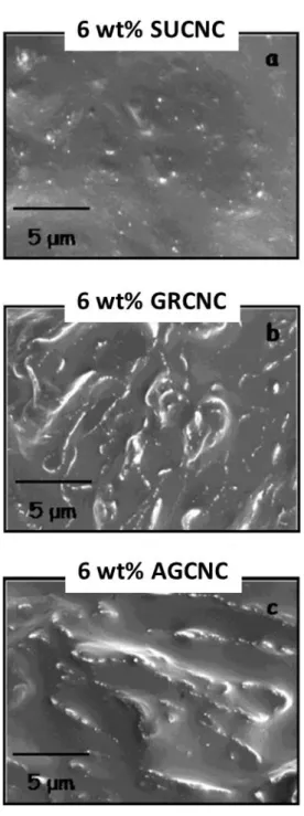
g/mol) onto the CNC, referred to as compatibilized CNC. They prepared the composites via a solvent casting method with toluene as solvent. Figure 2.6 presents SEM micrographs of surface modified (SUCNC), compatibilized (GRCNC) and unmodified CNCs (AGCNC) in aPP. Obviously, there are much finer agglomerates in the surface modified system. However, grafting of PP-g-MA to CNCs seems not to be effective to favor a better dispersion and distribution of CNCs within aPP.
Figure 2.7 reports the storage modulus of the samples for DMTA tests. As expected, unfilled aPP shows very low modulus above Tg, almost 3 orders of magnitude lower than that of iPP. By
incorporating 6 wt% surface modified, compatibilized and unmodified CNCs the rubbery-region storage modulus of iPP is enhanced by 1 order of magnitude at room temperature, i.e. 25 °C. However, the addition of unmodified CNCs results in better enhancement compared to the surface modified and compatibilized CNCs (Figure 2.7a). The possible reason could be the plasticization effect of the surfactant and compatibilizer materials on the properties of aPP. The same observations were reported for tensile properties of the samples. Figure 2.8 presents the stress-strain behavior of the samples in tensile tests. Higher Young modulus and tensile strength, but reduced strain at break, are obtained for the aPP-CNC samples (Figure 2.8a). The use of surfactant and compatibilizer does not show any improvement of the mechanical properties of aPP containing unmodified CNCs. In another work they employed the same types of CNCs to enhance the mechanical properties of isotactic PP (iPP) [40]. For iPP-CNC samples, a decrease in the crystalline content of iPP was reported by incorporating 6 wt% of unmodified, surface modified and compatibilized CNC [40].
Figure 2.6: SEM micrographs of aPP composite films reinforced with 6 wt % (a) surface modified CNCs (SUCNC), (b) compatibilized CNCs (GRCNC), and (c) unmodified CNCs (AGCNC) (from Ref. [39])
In DMTA tests, the storage moduli for the samples filled with unmodified and surface modified CNCs were identical and higher than those of iPP and iPP filled with compatibilized CNCs in the rubbery region (i.e. temperatures higher than Tg) (Figure 2.7b). However, in the glassy region (i.e.
temperatures lower than Tg), only surface modified CNCs could increase the storage modulus of
PP; the other filled samples showed lower storage modulus (Figure 7b). In tensile tests, iPP filled with unmodified CNCs showed a decreased tensile strength, relative to the neat iPP; however, by incorporating compatibilized CNCs into iPP the tensile strength was enhanced, compared to the neat iPP. Better enhancement was observed for iPP filled with surface modified CNCs (Figure 2.8b).
Figure 2.7: Storage modulus vs temperature from DMTA tests comparing (a) neat aPP and (b) neat iPP with composites reinforced with 6 wt% unmodified CNCs (AGCNC), surface modified CNCs (SUCNC), and compatibilized CNCs (GRCNC) (adapted from Ref. [39, 40])
Figure 2.8: Stress vs strain curves for (a) neat aPP and (b) neat iPP and composites reinforced with 6 wt% AGCNC, SUCNC, and GRCNC (adapted from Ref. [39, 40])
Bahar et al. [41] employed the same solvent casting method to prepare PP-CNC composites compatibilized with PP-g-MA (Epolen E 43-Wax, softening point 158 °C, 8 wt% MA, molecular weight Mw: 15,789 and Mn: 7,105). To do that, two different polymer solutions, namely PP in
toluene and PP-g-MA in toluene, were prepared at 105-110 °C. Then, the desired amount of CNCs were added into the solution of PP-g-MA and sonication together with stirring applied for 2 h before the addition of this mixture to the solution of PP in toluene. The final mixture was stirred for another 15 min and poured into petri dishes for solvent evaporation, conducted in oven at 90 °C for 24 h. The samples for testing were prepared by compression at 135 °C. The concentration of CNCs in final composites was 5, 10 and 15 wt%. Two sets of samples compatibilized with different contents of PP-g-MA (0.8 and 2 wt% of the systems) were compared in terms of their crystallinity and tensile properties. Figure 2.9 compares the tensile strength of the samples. By incorporating 0.8 wt% PP-g-MA the tensile strength of PP composite increased. However, adding 2 wt% PP-g-MA into PP resulted in to smaller increase (Figure 2.9a). The addition of 5 and 10 wt% CNCs did not enhance the tensile strength of the blends, while for 15 wt% CNCs enhanced tensile strength as shown in Figure 2.9b. The main reason behind this trend is probably the change in the crystalline content of the composites. A reduced crystalline content for filled blend with 5 wt% CNCs, no significant changes for 10 wt% CNCs and ca. 50% increase in crystalline content at 15 wt% CNCs are reported, relative to the value of the PP and PP-g-MA blend. A better comparison is possible via Table 2.3. For all of the filled blends, a reduced tensile modulus is observed, compared to the unfilled blends. Interestingly, the strain at break for the blends is increased by the addition of CNCs, although compared to the neat PP it is reduced. The results do not show the efficiency of PP-g-MA as a compatibilizer except for the system containing 15 wt% CNCs. This contrasts the advantage of nanocomposites as usually a concentration of less than 10 wt% is desired. Moreover, the results of uncompatibilized systems were not presented in the work of Bahar et al. [41] to check the efficiency of the compatibilizer.
Hassanabadi et al. [42] designed more systematic experiments to investigate the effect of five different PP-g-MA compatibilizers1, varying in acid number and molecular weight, on the
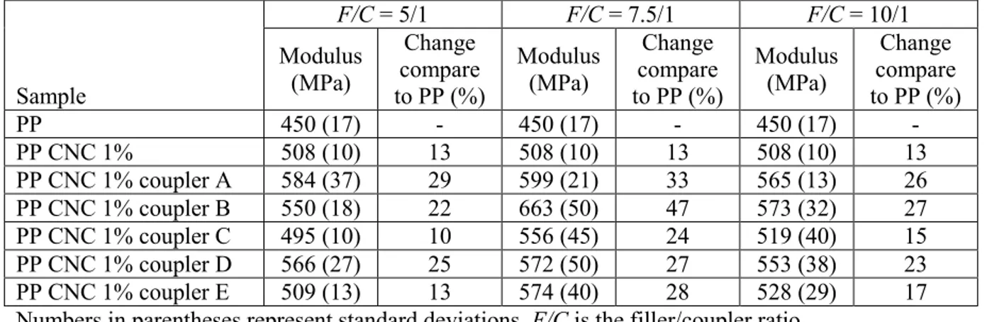
mechanical properties of PP through a melt preparation method. The composites were prepared via a twin screw extruder and direct melt mixing. The PP and PP-g-MA compatibilizers were dry mixed and introduced from the first feeder; CNC powder was added through a second feeder to reach the final concentration of 1 wt% CNCs with different CNC to compatibilizer ratios. The product was pelletized and introduced into the extruder for a second run. The samples were characterized by tensile, impact and flexural tests. For all of the compatibilizers the optimum ratio of CNC to compatibilizer was determined at 7.5/1, regardless of the molecular weight and acid number. Table 2.4 reports the Young modulus of the samples with different compatibilizers and CNC to compatibilizer ratios. The highest Young modulus improvement (47% compared to the neat PP) was achieved for the compatibilizer with Mw: 15 kDa, acid number of 41 mg
KOH/g; the highest flexural modulus enhancement (32% relative to the neat PP) was obtained for the compatibilizer with Mw: 51 kDa and acid number of 15 mg KOH/g. However, the impact
strength slightly decreased for all samples. Therefore, they concluded that the most important parameter when using PP-g-MA as a compatibilizer is the CNC/compatibilizer ratio. However, the results of PP filled with uncompatibilized CNC were not reported and all compatibilizers had different values of molecular weight and acid number making the comparison difficult; but the acid number seemed to be more effective than the molecular weight to enhance the mechanical properties. A higher acid number value would favor better wetting of CNCs by the compatibilizer and a higher value of molecular weight would lead to stronger entanglements with PP matrix, although for both parameters there are optimum values.
Khoshkava and Kamal [43] determined the effects of CNC drying process, initial concentration of the CNC aqueous suspensions and final concentration in the nanocomposites on the properties of PP-CNC systems. They obtained a porous morphology for the CNC agglomerates by employing a spray-freeze drying process, which led to property enhancements of PP without the need of a third component. Figure 2.10 presents the SEM micrographs of spray-freeze dried CNCs (CNCSFD) with different initial concentrations in water and final concentrations in PP. Figure 2.10a,b show agglomerates obtained after spray-freeze drying process of aqueous suspensions of CNCs with different concentrations prior to the drying process. Large agglomerates with a very porous structure and low strength are obtained that can be broken down easily when introduced into PP at molten state thereafter. Also there is high potential for PP melt infiltration into these porous agglomerates. Therefore, a uniform dispersion of the CNCs into PP
was achieved (Figure 2.10c,d). The small holes in Figure 2.10c−e are considered spray-freeze dried CNCs that were pulled out during sample preparation for SEM by microtoming. However, the holes could be micro-voids caused by partial polymer melt infiltration into the porous structure of the CNC agglomerates. It seems that a lower initial concentration, i.e. 1 wt%, by providing a more open structure, resulted in easier polymer melt infiltration and, consequently, more dispersed CNCs into PP.
Figure 2.9: Tensile strength of: (a) neat PP, PP with 0.8 wt% MA, and PP with 2 wt% PP-g-MA; (b) PP-PP-g-MA blend with 0.8 wt% PP-g-MA and different CNC contents (from Ref. [41]) Table 2.3: Tensile properties of neat PP, PP and PP-g-MA blends, and filled blends (adapted from Ref. [41])
Sample Tensile strength (MPa) Elongation at break (%) Modulus (MPa)
PP reference 25.7 24.9 1258.5 08 ma* reference 41.6 5.2 1534.0 08 ma 5 CNC 39.5 5.5 1498.2 08 ma 10 CNC 41.1 9.76 990.0 08 ma 15 CNC 44.4 7.38 1258.4 08 ma 15 CNC 30 son 40.9 5.61 1129.7 08 ma 15 CNC 60 hyd 46.6 7.4 1295.6 2 ma reference 33.5 2.17 1777.4 2 ma 5 CNC 32.8 4.3 1417.5 2 ma 10 CNC 36.4 5.4 1013.5 2 ma 15 CNC 39.0 4.8 1336.1
Table 2.4: Young modulus of the samples prepared with different compatibilizers and CNC to compatibilizer ratios. The concentration of CNC is fixed at 1 wt% (adapted from Ref. [42])
Sample F/C = 5/1 F/C = 7.5/1 F/C = 10/1 Modulus (MPa) Change compare to PP (%) Modulus (MPa) Change compare to PP (%) Modulus (MPa) Change compare to PP (%) PP 450 (17) - 450 (17) - 450 (17) - PP CNC 1% 508 (10) 13 508 (10) 13 508 (10) 13 PP CNC 1% coupler A 584 (37) 29 599 (21) 33 565 (13) 26 PP CNC 1% coupler B 550 (18) 22 663 (50) 47 573 (32) 27 PP CNC 1% coupler C 495 (10) 10 556 (45) 24 519 (40) 15 PP CNC 1% coupler D 566 (27) 25 572 (50) 27 553 (38) 23 PP CNC 1% coupler E 509 (13) 13 574 (40) 28 528 (29) 17 Numbers in parentheses represent standard deviations. F/C is the filler/coupler ratio.
Figure 2.10: SEM images of: (a) spray-freeze dried CNC obtained from 1 wt% CNC aqueous suspension (CNCSFD1), (b) spray-freeze dried CNC obtained from 2 wt% CNC aqueous suspension (CNCSFD), (c, e) PP containing 5 wt% CNCSFD1 and (d, f) PP containing 5 wt% CNCSFD2 at (c, d) low and (e, f) high magnification (from Ref. [43])
The rheological behavior in small-amplitude oscillatory shear (SAOS) was also investigated. Figure 2.11 presents the complex viscosity, storage and loss moduli versus frequency in SAOS tests for PP filled with spray dried, freeze dried and spray-freeze dried CNCs. It seems that almost insignificant polymer melt infiltration took place within the compact structures of CNC agglomerates, obtained from spray and freeze drying; that resulted into no rheological property increases (Figure 2.11a). However, with the porous structure of spray-freeze dried CNCs polymer melt infiltration happened and, as a result, the complex viscosity and storage and loss moduli increased, especially at low frequencies (Figure 2.11b,c). Observation of a high shear-thinning behavior for the complex viscosity and frequency-independency behavior for the storage and loss moduli at low frequencies are ascribed to a CNC network formation. With further rheological characterization, a value of 2.5 wt% was reported as the rheological percolation threshold in the best case, i.e. when the initial concentration of CNCs in the aqueous suspension was 1 wt% prior to spray-freeze drying [43].
To compare the mechanical performance of PP and PP filled with spray died and spray-freeze dried CNCs, DMTA data for the samples were presented [43]. Figure 2.12 reports the variation of storage modulus for a wide range of temperature. The addition of spray dried CNC decreased the storage modulus of PP for the whole range of temperature due to poor dispersion and existence of large agglomerates. However, by incorporating 5 wt% spray-freeze dried CNCs enhanced storage modulus, up to ca. 60% at room temperature, is observed. The nanoparticles were less efficient to improve the properties when the initial concentration of CNC was larger, i.e. at 2 wt% compared to 1 wt%.
Figure 2.11: Plots of (a,b) complex viscosity vs angular frequency for (a) PP, PP with 5 wt% spray-dried (CNCSD) and freeze-dried (CNCFD) CNC, and (b) PP and PP containing CNCSFD1 agglomerates, and (c) storage and loss moduli vs angular frequency of samples. The insets show SEM images of spray-dried (CNCSD), freeze-dried (CNCFD), and spray-freeze-dried (CNCSFD) CNC agglomerates (adapted from Ref. [43])
Figure 2.12: Storage modulus vs temperature for PP and PP containing 5 wt% CNCSD, CNCSFD1, and CNCSFD2 (from Ref. [43])
2.7 PLA-CNC (nano)composites
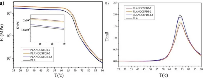
Kamal and Khoshkava [44] used the same idea of spray-freeze drying employed for PP-CNC systems [43] to prepare PLA-CNC nanocomposites with a dispersed structure and enhanced properties. Figure 2.13 illustrate the quality of the dispersion when 7 wt% of spray dried CNCs (CNCSDs) and spray-freeze dried CNCs (CNCSFDs) were melt-compounded with molten PLA via an internal mixer. Very large agglomerates were formed with poor dispersion and distribution for PLA filled with CNCSDs (Figure 2.13a), while a uniform and dispersed structure was obtained when CNCSFDs were added to PLA (Figure 2.13b). Figure 2.14 presents the complex viscosity, storage and loss moduli versus frequency for PLA and PLA-CNC nanocomposites with different CNC contents. Significant increases of the complex viscosity, storage and loss moduli for PLA containing spray-freeze dried CNCs at concentration of 3 wt% and larger are observed, relative to the neat PLA. As discussed earlier, the formation of a CNC network within the PLA is responsible for this huge increase in rheological properties. Moreover, Kamal and Khoshkava [44] performed DMTA tests to compare the mechanical properties of the samples. Figure 2.15 illustrates the variations of the storage modulus and tan δ over a wide range of temperature. The storage modulus is increased up to ca. 27% in the glassy region and up to ca. 20% in the rubbery
region for PLA containing 7 wt% CNCs (Figure 2.15a). Figure 2.15b reports a reduction in the area under tan δ peak, which is usually ascribed to the restriction effect of the CNCs on the segmental motion of the polymer chains at Tg. These observations clearly demonstrate the
reinforcing effect of the CNCs on the properties of PLA. Again, there would be a concern that the holes observed in Figure 2.13b are micro-voids rather than pulled out CNCs.
Figure 2.13: SEM micrographs of PLA containing 7 wt% of (a) spray dried CNC (CNCSD) and spray-freeze dried CNC (CNCSFD) (Scale bars: 10 μm) (from Ref. [44])
Pei et al. [45] extracted CNCs from cotton and partially modified them with a silane coupling agent, namely n-dodecyldimethylchlorosilane, in a toluene medium. Partially silylated CNCs could form stable suspensions in tetrahydrofuran and chloroform revealing the hydrophobic surface of silylated CNCs. PLA-CNC films were prepared via a solvent casting method in a chloroform medium. For the sake of comparison PLA films with unmodified CNCs were also prepared. Figure 2.16 reports DSC data from cooling cycle for the samples at a rate of 10 °C/min.
Figure 2.14: Complex viscosity, storage and loss moduli vs frequency for PLA and PLA-CNC nanocomposites. The initial concentration of CNC in the aqueous suspensions was 3 wt% prior to spray-freeze drying (adapted from Ref. [44])
Figure 2.15: The DMTA data for neat PLA and PLA-CNC nanocomposites with 1.5, 3 and 7 wt% spray-freeze dried CNCs: (a) storage modulus and (b) tan δ vs temperature (from Ref. [44])
One of the main industrial problems of PLA is its slow crystallization. Therefore, under fast and even moderate cooling rates PLA does not undergo crystallization. The incorporation of unmodified CNCs did not solve the problem. However, by the addition of silylated CNCs the crystallization took place.
Table 2.5 provides details from heating cycles. The addition of 1 wt% modified CNCs resulted into the highest crystalline content, almost 100% increase relative to the neat PLA and PLA filled with unmodified CNCs. However, by the addition of more modified CNCs, a lower enhancement in the total crystalline content of PLA was achieved. Moreover, they reported reduced half-time of crystallization for PLA samples filled with modified CNCs, especially when isothermal crystallization took place at higher temperatures. These observations definitely confirm the nucleation effect of the CNCs on the crystallization of PLA and the efficiency of the silane coupling agent to yield a better wetting of CNCs with the PLA matrix.
Table 2.6 reports the tensile properties of the PLA and PLA-CNC samples. The Young modulus and tensile strength were increased by ca. 27 and 21%, respectively, by incorporating 1 wt% of silylated CNCs. The main reason for these enhancements was ascribed to the increases in the crystalline content of PLA for modified CNC-filled samples. However, the strain at break significantly decreased by more than 70 % relative to the neat PLA. The addition of larger content of silane modified CNCs resulted in to lower enhancements, probably due to the plasticization effect of the silane modifier.
Figure 2.16: DSC runs in cooling cycles for PLLA and PLLA containing partially silylated (SCNC) and unmodified CNCs with final concentration of 1 and 2 wt% (from Ref. [45])
Fortunati et al. [46] investigated the effect of unmodified and surface modified CNCs, with an acid phosphate ester of ethoxylatednonylphenol, on the tensile properties of PLA. The composites were prepared by a solvent casting process in a chloroform medium. Table 2.7 reports
the tensile properties of the samples. By the addition of unmodified CNCs the tensile strength was increased. However, by surface modification the properties were decreased compared to the unmodified systems due to the plasticization effect of the surfactant on the properties of PLA, although it might favor a better dispersion of the particles within PLA matrix. However, the reported values are not typical of PLA, especially elongation at break which has been extensively reported smaller than 10%.
Table 2.5: Thermal parameters of PLLA and PLLA containing partially silylated (SCNCs) and unmodified CNCs with final concentrations of 1 and 2 wt%. Data derived from the heating DSC scans (adapted from Ref. [45])
Sample 𝑇𝑚 (⁰C) ∆𝐻𝑚 (J/g)a ∆𝐻𝑐𝑐 (J/g)a 𝑋𝑐 (%) PLLA 171.4 25.8 12.5 14.3 PLLA-CNC-1 171.4 28.2 12.9 16.4 PLLA-CNC-2 171.8 30.3 16.0 15.0 PLLA-SCNC-1 171.8 32.3 4.0 30.4 PLLA-SCNC-2 171.4 29.4 10.1 20.7 a Data corrected for the percentage of PLLA in the nanocomposites.
Table 2.6: Tensile properties of PLLA and PLLA-CNC composite films at room temperature (adapted from Ref. [45])
Sample Tensile modulus (GPa) Tensile strength (MPa) Elongation at break (%)
PLLA 1.1 ± 0.01 48.3 ± 2.9 31.1 ± 3.0
PLLA-CNC-1 1.0 ± 0.02 49.2 ± 0.4 10.5 ± 2.0
PLLA-CNC-2 1.2 ± 0.03 48.3 ± 0.4 12.2 ± 0.2
PLLA-SCNC-1 1.4 ± 0.08 58.6 ± 3.1 8.3 ± 0.6
PLLA-SCNC-2 1.4 ± 0.04 53.8 ± 2.1 7.1 ± 1.8
Table 2.7: Tensile properties of PLA and PLA containing surface modified (s-CNCs) and unmodified CNCs. The numbers in the formulation represent the concentration of CNCs in the systems, namely 1 and 3 wt% (adapted from Ref. [46])
Sample Yield stress (MPa) Elongation at yield (%) Tensile strength (MPa) Elongation at break (%) Young modulus (MPa) PLA 14.7 ± 5.1 2.3 ± 0.5 16.5 ± 3.1 277.9 ± 33.6 1205 ± 100 PLA-1CNC 31.3 ± 1.6 3.0 ± 0.5 27.1 ± 6.3 200.1 ± 53.3 1330 ± 90 PLA-1s-CNC 22.9 ± 4.2 2.6 ± 0.6 22.9 ± 1.2 286.1 ± 25.2 993 ± 190 PLA-3CNC 42.1 ± 2.0 2.7 ± 0.6 21.9 ± 3.5 100.9 ± 27.9 1930 ± 170 PLA-3s-CNC 25.7 ± 4.8 3.1 ± 0.1 20.2 ± 1.9 210.4 ± 48.1 800 ± 100