UNIVERSITÉ DE MONTRÉAL
MACHINABILITY OF TITANIUM METAL MATRIX COMPOSITES
(Ti-MMCs)
MARYAM ARAMESH
DÉPARTEMENT DE GÉNIE MÉCANIQUE ÉCOLE POLYTECHNIQUE DE MONTRÉAL
THÈSE PRÉSENTÉE EN VUE DE L’OBTENTION DU DIPLÔME DE PHILOSOPHIAE DOCTOR
(GÉNIE MÉCANIQUE) JUIN 2015
UNIVERSITÉ DE MONTRÉAL
ÉCOLE POLYTECHNIQUE DE MONTRÉAL
Cette thèse intitulée :
MACHINABILITY OF TITANIUM METAL MATRIX COMPOSITES
(Ti-MMCs)
présentée par: ARAMESH Maryam
en vue de l’obtention du diplôme de : Philosophiae Doctor été dûment acceptée par le jury d’examen constitué de: M. LAKIS Aouni A., Ph. D., président
M. BALAZINSKI Marek, Docteur ès sciences, membre et directeur de recherche M. ATTIA Helmi, Ph. D., membre et codirecteur de recherche
M. KISHAWY Hossam A., Ph. D., membre et codirecteur de recherche M. VADEAN Aurelian, Doctorat, membre
DEDICATION
I would like to dedicate my thesis to my dearest parents Parvin and Mehdi, beloved husband Ali and wonderful brother Nima.
ACKNOWLEDGEMENTS
I would like to express my profoundest gratitude to my supervisor Prof. Marek Balazinski, for his invaluable guidance, advice and support whilst encouraging me to peruse my own ideas throughout all these years. He has always been an inspiration to me in all aspects of my life for his wisdom, kindness and trust.
I would also like to thank sincerely my co-supervisors Profs. Helmi Attia and Hossam Kishawy for their continuous guidance, help and support. This work would not succeed without their precious advice.
I acknowledge the NSERC Canadian Network for Research and Innovation in Machining Technology (CANRIMT) for their financial support.
I would like to thank the aerospace structures, materials and manufacturing laboratory of the National Research Council Canada (NRC) for hosting me as a guest worker and providing me with their facilities. My deepest special thanks goes to Prof. Attia and his team for their endless support which is priceless.
I would like to thank my colleagues and office-mates Mehrdad Givi, Paul Provencher, Anna Los and Xavier Rimpault for their help and support. I also wish to thank my dear friends Shagha Rouzmeh, Shagha Attar and Mojdeh Tirehdast for their friendship, kindness and encouragements during all these years.
My sincere thanks goes to my family and my husband Ali Alem for their love, support and continuous encouragements.
RÉSUMÉ
Les composites à matrices métalliques de titane (Ti-MMCs), en tant que nouvelle génération de matériaux, ont plusieurs applications potentielles dans les domaines industriels de l’aérospatiale, et l’automobile. La présence de particules de céramique améliore les propriétés mécaniques et physiques de la matrice. Cependant, ces particules sont dures et abrasives par leur nature, ce qui cause de multiples difficultés pour leur usinabilité. L’usure sévère des outils ainsi que la vie utile très brève de ceux-ci représentent les inconvénients les plus importants de leur usinabilité. La littérature indique très peu d’études concernant leur usinabilité, en particulier pour l’estimation de la durée de vie utile et de l’usure des outils de coupe. Les outils de diamant polycristallin (PCD) semblent être le meilleur choix pour usiner les MMCs du point de vue des chercheurs. Malgré ceci, en raison de leur coût élevé, des alternatives abordables sont fort souhaitables. Les plaquettes de nitrure de bore cubique (CBN) demeurent les outils les plus durs après celles de PCD, démontrent d’excellentes qualités dont une grande résistance à l’usure, une bonne dureté à température élevée, un bas coefficient de friction et une température de fusion élevée. Toutefois, les outils de CBN n’ont pas encore été étudiés dans le contexte de l’usinage des Ti-MMCs. La présente étude élabore en profondeur les mécanismes d’usure des plaquettes de CBN durant le tournage des Ti-MMCs. La morphologie unique des faces usées des outils a été étudiée pour la première fois, menant à une nouvelle compréhension dans l’identification des mécanismes d’usure chimiques durant l’usinage des Ti-MMCs. De plus, la pleine exploitation de la vie utile des outils de coupe est critique en raison des dépenses importantes liées au remplacement non-optimal des outils de coupe. Ceci encourage fortement le développement d’une modèle fiable pour l’estimation de la vie utile pour toutes conditions de coupe. Cette étude élabore une nouvelle méthode découlant de la méthodologie d’analyse de survie (survival analysis) pour estimer les états d’usures successives des outils pour toutes conditions d’usinage des Ti-MMCs. Ce modèle statistique prend en compte la durée de l’usinage en plus des effets des paramètres de coupe. De cette manière, les résultats obtenus ont démontré un excellent accord avec les résultats expérimentaux. De surcroît, un modèle plus avancé a été développé en rajoutant l’usure des outils comme variable au modèle précédent. Il en sort un nouveau modèle proposé pour estimer la durée de vie utile restante des plaquettes usées pour des conditions d’usinage variables, en incluant l’usure actuelle des outils dans les données d’entrée. Les résultats de ce modèle ont été validés par expérimentation et le modèle concorde très bien avec les essais expérimentaux.
ABSTRACT
Titanium metal matrix composites (Ti-MMCs), as a new generation of materials, have various potential applications in aerospace and automotive industries. The presence of ceramic particles enhances the physical and mechanical properties of the alloy matrix. However, the hard and abrasive nature of these particles causes various issues in the field of their machinability. Severe tool wear and short tool life are the most important drawbacks of machining this class of materials. There is very limited work in the literature regarding the machinability of this class of materials especially in the area of tool life estimation and tool wear.
By far, polycrystalline diamond (PCD) tools appear to be the best choice for machining MMCs from researchers’ point of view. However, due to their high cost, economical alternatives are sought. Cubic boron nitride (CBN) inserts, as the second hardest available tools, show superior characteristics such as great wear resistance, high hardness at elevated temperatures, a low coefficient of friction and a high melting point. Yet, so far CBN tools have not been studied during machining of Ti-MMCs. In this study, a comprehensive study has been performed to explore the tool wear mechanisms of CBN inserts during turning of Ti-MMCs. The unique morphology of the worn faces of the tools was investigated for the first time, which led to new insights in the identification of chemical wear mechanisms during machining of Ti-MMCs. Utilizing the full tool life capacity of cutting tools is also very crucial, due to the considerable costs associated with suboptimal replacement of tools. This strongly motivates development of a reliable model for tool life estimation under any cutting conditions. In this study, a novel model based on the survival analysis methodology is developed to estimate the progressive states of tool wear under any cutting conditions during machining of Ti-MMCs. This statistical model takes into account the machining time in addition to the effect of cutting parameters. Thus, promising results were obtained which showed a very good agreement with the experimental results.
Moreover, a more advanced model was constructed, by adding the tool wear as another variable to the previous model. Therefore, a new model was proposed for estimating the remaining life of worn inserts under different cutting conditions, using the current tool wear data as an input. The results of this model were validated with the experimental results. The estimated results were well consistent with the results obtained from the experiments.
TABLE OF CONTENTS
DEDICATION ... III ACKNOWLEDGEMENTS ... IV RÉSUMÉ ... V ABSTRACT ... VI TABLE OF CONTENTS ... VII LIST OF TABLES ... XII LIST OF FIGURES ... XIII
INTRODUCTION ... 1 Problem definition ... 2 Research objectives ... 3 Main objective ... 3 Specific objectives ... 3 Hypotheses ... 4 THESIS ORGANIZATION ... 5
General technical overview ... 5
Chapters’ contents ... 6
LITERATURE REVIEW ... 9
Chapter 1 1.1 Introduction ... 9
1.2 Metal matrix composites (MMCs) ... 9
1.2.1 Titanium Metal Matrix Composites (Ti-MMCs) ... 10
1.3 Chip morphology ... 13
1.5 Cutting tools for machining MMCs ... 16
1.5.1 Tool wear mechanisms of CBN inserts ... 18
1.6 Tool life estimation ... 21
1.7 Conclusions of the literature review ... 24
ARTICLE 1: TOOL WEAR MECHANISMS OF CBN INSERTS DURING Chapter 2 TURNING OF TITANIUM METAL MATRIX COMPOSITES (TI-MMCS) ... 26
ABSTRACT ... 26
2.1 Introduction ... 27
2.2 Experimental set up ... 28
2.3 Methodology ... 29
2.4 Results and discussion ... 30
2.4.1 Wet machining ... 30
2.4.2 Dry machining ... 38
2.4.3 Titanium embrittlement during machining of Ti-MMCs and the effect on the surface integrity ... 42
2.5 Conclusions ... 44
2.6 Acknowledgement ... 45
2.7 References ... 45
ARTICLE 2: SURVIVAL LIFE ANALYSIS OF THE CUTTING TOOLS Chapter 3 DURING TURNING TITANIUM METAL MATRIX COMPOSITES (TI-MMCS) ... 49
ABSTRACT ... 49
3.1 Introduction ... 49
3.2 Experiment set up ... 51
3.3 Methodology ... 52
3.4.1 Fitting the reliability model ... 55
3.4.2 Transition time between states ... 55
3.4.3 Sojourn time ... 56
3.5 Conclusions ... 57
3.6 Acknowledgement ... 58
3.7 References ... 58
ARTICLE 3: SURVIVAL LIFE ANALYSIS APPLIED TO TOOL LIFE Chapter 4 ESTIMATION WITH VARIABLE CUTTING CONDITIONS WHEN MACHINING TITANIUM METAL MATRIX COMPOSITES (TI-MMCS) ... 60
ABSTRACT ... 60 4.1 Introduction ... 60 4.2 Experiment set up ... 63 4.3 Methodology ... 63 4.3.1 Experimental Procedure ... 64 4.3.2 Statistical procedure ... 65
4.4 Results and discussions ... 68
4.4.1 The total time to reach the end of the third state ... 70
4.4.2 Between-state transition times ... 72
4.5 Conclusions ... 77
4.6 Acknowledgement ... 77
4.7 References ... 78
ARTICLE 4: ESTIMATING THE REMAINING USEFUL TOOL LIFE OF WORN Chapter 5 TOOLS UNDER DIFFERENT CUTTING CONDITIONS: A SURVIVAL LIFE ANALYSIS DURING TURNING OF TITANIUM METAL MATRIX COMPOSITES (TI-MMCS) ... 81
5.1 Introduction ... 81
5.2 Experiment set up ... 83
5.3 Methodology ... 83
5.3.1 Experimental procedure ... 85
5.3.2 Statistical Procedure ... 87
5.4 Results and discussions ... 89
5.5 Conclusions ... 97
5.6 Acknowledgement ... 97
5.7 References ... 98
ARTICLE 5: META-MODELING OPTIMIZATION OF THE CUTTING Chapter 6 PROCESS DURING TURNING TITANIUM METAL MATRIX COMPOSITES (TI-MMCS) 102 ABSTRACT ... 102 6.1 Introduction ... 103 6.2 Experiment set up ... 104 6.3 Methodology ... 105 6.3.1 Optimization algorithm ... 106 6.4 Conclusions ... 114 6.5 Acknowledgment ... 114 6.6 References ... 114 GENERAL DISCUSSION ... 116 Chapter 7 7.1 Originality of the work and contribution to knowledge ... 120
GENERAL CONCLUSIONS ... 122
Chapter 8 8.1 Recommendations for Future Research Work ... 125
LIST OF TABLES
Table 1-1: Mechanical properties of Ti-MMC used in this study (Dynamet Technology, Inc.) ... 11
Table 3-1: Cutting parameters ... 52
Table 3-2: Time to failure for different states ... 54
Table 3-3: Weibull distribution parameters and MTTF for each case ... 55
Table 3-4: time to different transition points from tr=50s ... 56
Table 3-5: Sojourn time obtained from the statistical model and the experiment results ... 57
Table 4-1: Cutting independent variables and their values ... 64
Table 4-2: Cutting parameters for each experimental run ... 64
Table 4-3: Time the transition point in addition to the total time to the end of the third state for the fourth run (V=80 m/min, f=0.35 mm/rev, ap=0.2 mm) ... 65
Table 4-4: Parameters of the PH model corresponding to each criterion ... 69
Table 4-5: Designed experimental runs for the model validation ... 72
Table 4-6: Estimated total time to the end of the third state calculated from the model vs the average value obtained from the experiments for the validation runs ... 72
Table 4-7: Estimated transition times from state 2 to 3 calculated from the model vs the average values obtained from experiments for the validation runs ... 73
Table 4-8: Estimated transition times from state 1 to 2 calculated from the model vs the average values obtained from experiments for the validation runs ... 74
Table 5-1: Cutting parameters for each experimental run ... 85
Table 5-2: Basic data layout for the survival analysis (Kleinbaum et al., 1996) ... 86
Table 5-3: Parameters of the PH model ... 94
Table 5-4: Experimental runs for the model validation ... 96
LIST OF FIGURES
Figure 1: Research outline ... 8 Figure 1-1: Schematic of CHIP process used for production of near-net shape components (Dynamet Technology, Inc.) ... 11 Figure 1-2: Some applications of metal matrix composites such as turbine engine blades, space shuttle struts, F-16 landing gear, automotive engine components, and diesel engine pistons ... 12 Figure 1-3: The effect of tool wear on the surface roughness (W. Grzesik, 2010) ... 15 Figure 2-1: SEM image of the worn surface of a) CBN rake face b) CBN flank face under through-coolant turning with v=250 m/min, f=0.1 mm/rev and ap= 0.15mm, machining time
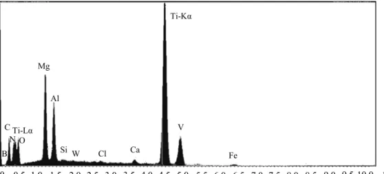
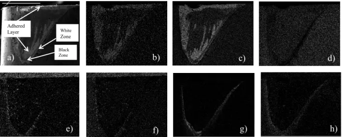
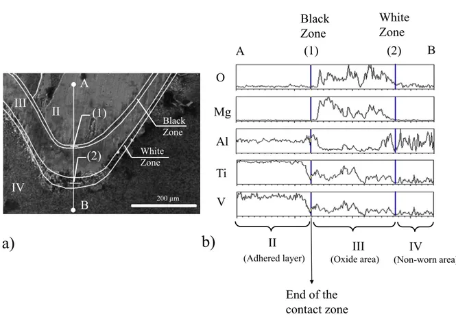
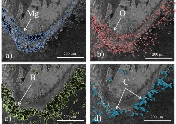
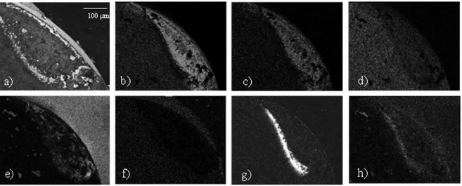
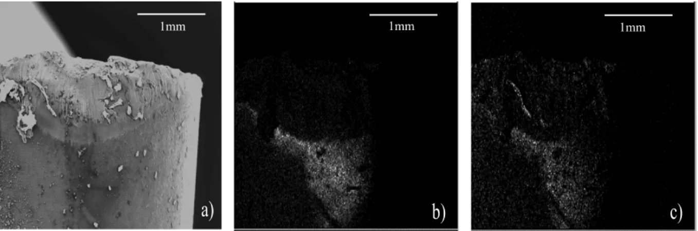
55 second ... 30 Figure 2-2: EDS result of the entire wear zone ... 31 Figure 2-3: a) SEM of entire flank worn area, Elemental maps of b) Titanium (Ti-Kα), c) Vanadium, d) Aluminum, e) Carbon, f) Boron, g) Magnesium and h) Oxygen (for the conditions given in Figure 2-1) ... 32 Figure 2-4: SEM images of increasing magnification (clockwise from a) of the CBN flank face showing the formation of a discontinuity between the adhered materials on the black zone (for the conditions given in Figure 2-1) ... 33 Figure 2-5: a) SEM image of the tool flank face b) EDS line scan of the tool flank face ... 34 Figure 2-6: SEM image of the flank face showing the different affected areas: abrasion in the contact area, oxidation outside the contact area, and abrasion plus oxidation in between .... 35 Figure 2-7: a) Elemental maps of a) Magnesium b) Oxygen, c) Boron and d) Carbon superimposed on the SEM image of tool flank worn area ... 36 Figure 2-8: a) SEM of entire rake worn area, Elemental maps of b) Titanium (Ti-Kα), c) Vanadium, d) Aluminum, e) Carbon, f) Boron, g) Magnesium and h) Oxygen (for the conditions given in Figure 2-1) ... 38
Figure 2-9: a) SEM image of the tool flank face after dry machining with v=300 m/min, f=0.1 mm/rev and ap= 0.15mm, machining time 40 seconds, b) oxygen map, c) magnesium map 38
Figure 2-10: a) SEM image of the entire rake worn area, and elemental maps of b) Titanium (Ti-Kα), c) Vanadium, d) Aluminum, e) Carbon, f) Boron g) Magnesium and h) Oxygen, after
dry machining with v=350 m/min, f=0.1 mm/rev and ap= 0.15mm ... 39
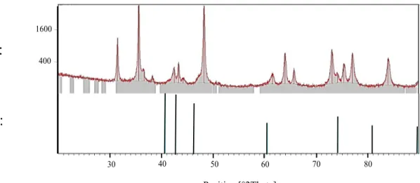
Figure 2-11: Comparison between the diffraction patterns of CBN after dry machining with HBN pattern (pdf no. 260773) ... 40
Figure 2-12: a) SEM of the flank face of a carbide insert (TH1000) after dry machining of Ti-MMC with v=80 m/min, f=0.1 mm/rev and ap= 0.15mm, b) oxygen map, c) magnesium map ... 41
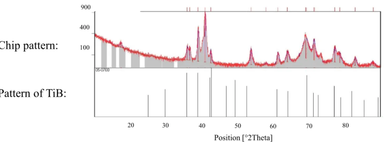
Figure 2-13: Comparison between the diffraction pattern of generated chips and the pattern of TiB (pdf no. 050700) ... 43
Figure 2-14: Generated machined surface ... 43
Figure 2-15: SEM image showing the fracture and crack initiation on the machined part ... 44
Figure 3-1: The tool wear curve ... 50
Figure 3-2: The experiment set up ... 51
Figure 3-3: Tool wear curve for 6 inserts ... 54
Figure 4-1: Tool life curves for v=80 m/min, f=0.35 mm/rev and ap= 0.2 mm ... 68
Figure 4-2: Points 1, 3 and 5 correspond to the greatest decrease in slope along the tool wear curves, indicating the first transition points; Points 2, 4 and 6 correspond to the greatest slope increase, indicating the second transition points for replications # 1, #2 and #4 respectively. The corresponding tool wear values are presented in the attached table. ... 69
Figure 4-3: Reliability functions for v=60 m/min and f=0.25 mm/rev obtained from the Weibull model vs PHM ... 70
Figure 4-4: Reliability functions for v=80 m/min and f=0.15 mm/rev from the Weibull model vs PHM ... 71
Figure 4-5: For each run of Table 4-2, the center bar of each run shows the estimated tool life calculated from the model. The 95% confidence limits are shown to each side of each center
bar ... 71
Figure 4-6: 3D plot of estimated total time to the end of the third state for different cutting speeds and feed rates ... 75
Figure 4-7: 3D plot of estimated time to the second transition point for different cutting speeds and feed rates ... 75
Figure 4-8: 3D plot of estimated time to the first transition point for different cutting speeds and feed rates ... 76
Figure 5-1: Sequence of steps required for calculating the remaining tool life via PHM ... 84
Figure 5-2: Tool wear curves and defined failure criterion for the cutting conditions: ... 89
Figure 5-3: a) SEM image of the tool flank face after machining of Ti-MMCs at V= 80 m/min, 91 Figure 5-4: SEM image of the tool flank face, showing the holes and vertical scratches as the result of two body and three body abrasion wear mechanisms occurred during machining of Ti-MMCs at V= 60 m/min, f= 0.15, ap= 0.2, with carbide tool (Seco TH1000) ... 91
Figure 5-5: Tool life curve for different replications of Run # 4 ... 92
Figure 5-6: Calculated tool lives associated with different tool wear levels in addition to the time to failure, for the 1st replication of Run #4 ... 93
Figure 5-7: Event status for different observations of the Run #4 at the first level of tool wear 7- b) Event status for different observations of the Run #4 at the second level of tool wear .... 94
Figure 5-8: Remaining tool life versus cutting conditions calculated for cutting inserts with: ... 95
Figure 5-9: Estimated remaining tool life calculated from the model vs the data obtained from the experiments for the validations runs 6 (a) to run 9 (d) ... 96
Figure 6-1: The experiment set up ... 104
Figure 6-2: An example showing the trade-off line ... 106
Figure 6-3: Three trade-off zones in cutting parameters space ... 107
Figure 6-5: The trade-off zones in cutting parameters space from another perspective ... 108 Figure 6-6: Three-dimensional plots of (a) the tool wear/MRR, and (b) the surface roughness (for zone 1 at feed rate= 0.2 mm/rev) ... 109 Figure 6-7: Contours of (a) the tool wear/MRR, and (b) the surface roughness (for zone 1, at feed rate= 0.2 mm/rev) ... 110 Figure 6-8: Contours of (a) the tool wear/MRR, and (b) the surface roughness (for zone 2, at feed rate= 0.15 mm/rev) ... 111 Figure 6-9: Grooves and scratches generated on (a) the tool flank face and (b) the workpiece surface during turning Ti-MMCs at v=100 (m/min), f= 0.15 (mm/ rev) and ap= 1 (mm) ... 112
Figure 6-10: Contours of tool wear/MRR, and (b) Contours of surface roughness (zone 3, for depth of cut = 0.8 mm) ... 113
INTRODUCTION
Metal matrix composites (MMCs) offer such an outstanding combination of preferred characteristics that cannot be excluded from our daily life anymore. In order to achieve a valuable modification in various properties of materials, metallic matrices are reinforced with additional phases upon extra requirements on chemical and/or physical properties. The resultant custom-made materials offer desired characteristics such as light weight, high wear resistance, high physical, thermal and mechanical properties. Thus, they demonstrate various potentials in different industries such as aerospace, transportation and automotive (Kainer, 2006).
Titanium metal matrix composites (Ti-MMCs) benefit from both desired characteristics of the titanium alloy matrix such as light weight, high temperature and wear resistance, in addition to high toughness provided by the TiC reinforcing particles (Pramanik et al., 2008). Thus, they exhibit a combination of preferable mechanical and physical properties. Despite all these brilliant characteristics, these materials suffer from poor machinability mostly due to the presence of extremely hard and abrasive reinforcements. The interaction between the tool and reinforcing particles induces a complex deformation behavior in MMC structures, resulting in propagation of cracks and voids on the surface of the material and consequent low accuracy and poor surface finish. In addition, low thermal conductivity, low modulus of elasticity and chemical reactivity of titanium alloys rise additional challenges in the field of their machinability (Davim, 2008; Hosseini & Kishawy, 2014).
Severe tool wear and very short tool life are technically the most important drawbacks of machining of Ti-MMCs. Thus, analyses of tool life and tool wear could be considered as one of the most important criteria for their machinability. Polycrystalline diamond (PCD) tools have been introduced as the most effective tools for machining MMCs (Heath, 2001). However, their high cost strongly motivates seeking out more cost effective alternatives. Cubic boron nitride (CBN) inserts, as the second hardest available tools, show potentials as an alternative for machining of MMCs. Yet, there is no literature regarding the tool wear mechanisms of these inserts during machining of Ti-MMCs.
Huge costs associated with sub-optimal tool replacements are a call for the development of a reliable model for estimating the remaining life of inserts under different cutting conditions. This is
even more crucial for machining Ti-MMCs, where severe tool wear results in a very short life. Moreover, non-homogeneous distribution of reinforcing particles results in considerable variability of the tool wear data. Therefore, developing a model based on the theory of probability appears to be the best option for modelling the progressive states of tool wear for this class of materials. Reliable and safe reuse of worn inserts would not be possible without an accurate estimation of their remaining lives till failure. Yet, so far no model has been proposed for predicting the remaining life of worn inserts, using the tool wear data as the input. Development of a model capable of fulfilling this task significantly contributes in cost reduction and productivity increase in machining processes.
Problem definition
High tool wear, short tool life and poor surface quality are the most important issues which are of concern during machining of Ti-MMCs. Hard and abrasive nature of the reinforcing particles are responsible for severe abrasive tool wear. Two-body abrasion wear takes over when the reinforcing particles abrade the cutting tool material while they are tightly confined in the matrix material. Whereas in three-body abrasion, tool wear could also occur when the debonded particles from the matrix roll between the tool and the workpiece. Consequently holes and cavities are generated on the tool surface (H. A. Kishawy et al., 2005). Also, debonding, fracture and cracking of particles would cause voids and cavities on the surface of the workpiece which will highly affect the surface integrity and result in poor surface finish.
Titanium alloy matrix also rises its own machining challenges, mainly due to its thermal and chemical characteristics such as poor thermal conductivity and chemical reactivity at elevated temperatures (Hosseini, Kishawy, et al., 2014).
Due to a very low thermal conductivity of the titanium alloy matrix, extremely high local temperatures are generated in a very small area around the cutting edge. The extremely high contact temperature will result in high tool wear rates during their machining operations. Moreover, oxidation and other chemical wear mechanisms will be involved and further reduce the tool life.
During machining of Ti MMCs, segmented chips are produced that can induce force fluctuations and tool wear variations leading to lack of accuracy. Serrated chips on the trailing edge and
material side flow are also two phenomena which occur during machining MMCs and result in surface deterioration.
Research objectives
Main objective
There is a significant lack of data in the field of machinability analysis of Ti-MMCs. The main objective of this study is to perform a comprehensive study for tool wear and tool life estimation during machining of Ti-MMCs, since these studies are considered as the most important criteria in any machinability analysis.
Specific objectives
• A comprehensive study on the tool wear mechanisms of CBN inserts during turning of
Ti-MMCs.
Tool wear mechanisms of CBN inserts, as the second candidate for machining of MMCs, during turning of titanium metal matrix composites (Ti-MMCs) were investigated. Adhesion, abrasion, chemical interactions and their effects on the wear surface morphology were investigated in detail.
• Estimating the progressive states of tool wear for machining of Ti-MMCs with
variable cutting conditions.
A novel model based on the survival analysis methodology is developed for estimating the progressive states of tool wear under different cutting conditions during machining of Ti-MMCs. The model accounts for the machining time in addition to the effect of cutting variables, thus it delivers accurate results.
• Estimating the remaining useful tool life of worn tools under different cutting
conditions.
Another more advanced survival model is developed for estimating the remaining life of worn inserts under different cutting conditions. The data regarding the tool wear itself was added as a variable into the model, in addition to the cutting parameters. Thus, the new model was capable of predicting the remaining life of worn inserts, using the current tool wear value as the input data.
Hypotheses
• Maximum flank wear length, VBBmax, is an accepted measure for quantification of the tool life.
VBBmax is often used for tool life analysis, since it is easy to quantify and also due to its influence
on the accuracy and surface integrity of the machined part (Davim & Astakhov, 2008)
• Maximum flank wear length, VBBmax, at the second transition point of the tool wear curve is considered as the tool failure criterion in machinability analyses
Severe vibration, temperature and cutting forces are induced at the third state of tool wear curve. Thus, during any machining process, entering this state should be avoided in order to prevent any serious detriments to the tool and machined surface. The tool wear associated with the transition between the second and third state is often regarded as the tool life criterion (Astakhov, 2013).
• Tool life and tool wear are affected by the cutting conditions
Several factors could affect the tool life and tool wear. Yet, cutting conditions specially the cutting speed are of prime concerns, due to their significant effect on the tool wear and consequently the tool life (Astakhov, 2013).
THESIS ORGANIZATION
General technical overview
For the purpose of clarifying the thesis organization, the following provides a general technical overview of the thesis.
This study contains two major phases. In the first phase (Chapter 2), the tool wear mechanisms of CBN inserts, as the second potential alternative tools for machining of Ti-MMCs, were discussed in detail.
In the second phase, the tool life estimation was performed, using survival analysis methodology. The second phase include three steps:
At the first step (Chapter 3), a fixed cutting condition was adopted and only the effect of aging was considered in the Weibull model. The time to reach each state of tool wear and the total sojourn time spent in each state was calculated.
At the second step (Chapter 4), a proportional hazards model with a Weibull baseline was developed. Thus, the effect of cutting conditions in addition to the effect of aging were reflected in the model. Therefore, the time to reach each state under variable cutting conditions were obtained. In the third step (Chapter 5), tool wear was also added to the previous model. Thus, the remaining life of worn cutting inserts under different cutting conditions was calculated. Due to the importance of the second tool wear transition point, this point was used as the failure criterion for the last model.
At the end (Chapter 6), a complementary analysis was also performed to find the optimum cutting conditions during machining of Ti-MMCs.
Each chapter stated above contains a journal paper corresponding to the mentioned topic.
Following the aforementioned steps and the objectives of this study, more details regarding the chapters’ contents are provided below.
Chapters’ contents
1- Chapter 1 provides the literature review on the most important aspects of the machinability of MMCs including the chip shape, surface integrity and tooling. A comprehensive literature review is provided on the tool selection for machining of MMCs and the previous researches performed on the CBN inserts for machining of MMCs. Moreover, the current proposed methods for tool life estimations are discussed in this section. This study provides insight into the existing research, the existing problems and missing links thereof which should be addressed.
2- Chapter 2 provides the results of the comprehensive study on the tool wear mechanisms of CBN inserts during turning of Ti-MMCs. Various tool wear mechanisms, including adhesion, abrasion and chemical wear mechanisms were investigated and their effects on the unique wear morphology of the inserts were discussed. Furthermore, for the first time, the embrittlement of titanium alloys during machining of Ti-MMCs was studied. The root causes were investigated and the effect on the wear surface morphology and also on the machined surface was investigated.
3- Chapter 3 provides the steps required to estimate the progressive states of tool wear for a constant cutting condition. The condition used is typical for this tool and material, based on the recommendation of the tool supplier. Thus, only the effect of aging (t) is reflected in the Weibull model used in this study. The mean residual life (MRL) function is also introduced. The procedure for estimating the transition time between each state of tool wear, in addition to the total sojourn time spent in each state are explained.
4- Chapter 4 introduces the novel method for estimating the progressive states of tool wear of new inserts for any cutting conditions using a proportional hazards model (PHM) with a Weibull baseline. Applying the PHM as the predictive model, the effect of cutting conditions and aging are taken into account. Thus, an accurate model is developed for estimating the transition time between each state of tool wear under different cutting conditions. It should be mentioned that since Ti-MMCs are produced near net shape, usually only semi-finishing tests are required for the final product. Thus, only cutting speed (V) and feed rate (f) are considered as the controllable variables of this study.
5- Chapter 5 introduces a more advanced novel method for estimating the remaining useful life of worn cutting inserts under different cutting conditions during turning of Ti-MMCs, using the current tool wear value (VB) of the worn tool as the input data. Tool wear at the transition point between the second and third states of tool wear is considered as the failure criterion. Tool wear data is added as another variable (monitoring variable) to the PH model (explained in chapter 4) in addition to cutting conditions. Thus, the valuable information regarding the remaining life of worn inserts under different cutting conditions are obtained.
6- Chapter 6 presents the results of a complementary research performed in collaboration with Dr. Ashraf at American University of Cairo. Optimization of cutting conditions is also considered as a very important piece of data which complements the machinability analysis. Furthermore, there is no data regarding the multi-objective optimization of cutting conditions during machining of Ti-MMCs. Multi objective optimization has been performed to find the cutting conditions that result in minimum tool wear and surface roughness, while preserving the highest productivity. For this study, cutting speed (V), feed rate (f) and depth of cut (ap) were considered as variables; and surface roughness (Ra) and
tool wear (VB) were selected as the response parameters.
7- General discussions including the originality of the work and contributions to the knowledge are provided in chapter 7.
8- In chapter 8, the general conclusions of the present work, list of publications as well as suggestions for the future works are presented.
In order to better visualize the different phases of this study and to illustrate the different variables and methodologies involved in each phase, the outline of this research is summarized in Figure 1.
Figure 1: Research outline Exp er ime ntal An aly sis CBN Insert Chips SEM Analysis EDS Analysis XRD Analysis
Tool Wear Mechanism of CBN inserts (Ch. 2) Variables/ Samples Methodology/ Analysis Results Analy tic al An aly sis PH Model PH Model Multi-objective Optimization
Tool Life Estimation Variable Cutting Cond.
New Tools (Ch. 4) Tool Life Estimation Variable cutting Cond.
Worn Tools (Ch. 5) Optimization of Cutting Conditions (Ch. 6) ap V f VB t Weibull Model
Tool Life Estimation Fixed Cutting Cond. (Ch. 3)
LITERATURE REVIEW
Chapter 1
1.1 Introduction
It is reported that the first research on machinability of metal matrix composites goes back to 1985, on the investigation of wear mechanisms during machining of aluminum metal matrix composite, performed by Burn et al. (Brun et al., 1985). In 1990s deep investigation on the machining of MMCs started (Davim, Pramanik, et al., 2008; Songmene et al., 1999). However, most of the research efforts regarding the machinability of the MMCs are focused on aluminum MMCs and there is a significant lack of data regarding the machinability analysis of Ti-MMCs. In the upcoming section, the contributions on the most important parameters of machinability of MMCs in the open literature are discussed. Chip shape, surface integrity, tool wear and tool life estimation which are considered as the main concerns of any machinability analysis, are covered in the literature review.
1.2 Metal matrix composites (MMCs)
Metal matrix composites (MMCs) are composed of non-metallic reinforcements in metal matrices, and show higher properties in comparison to the monolithic materials. MMCs can be either reinforced with particles, continuous long fibers or discontinuous ones in the form of whiskers. The most commonly used materials for reinforcing the metal matrix composites are ceramic fibers which inherit superior stiffness, strength and temperature stability (Seshan et al., 1996). Yet, production process of particulate composites is simpler and more cost effective than that of fiber reinforced composites. In comparison to whiskers, particles can be merged together more efficiently and with a higher volume percentage. No health concern has been reported yet in applying micrometer particles. Furthermore, applying them yields in less breakage of reinforcements in comparison to whiskers (Srivatsan et al., 2006).
Particles can be in any size, shape or configuration. They can have random or preferred orientations. Mostly the particles are distributed randomly, thus particulate composites show isotropic characteristics.
In general, particles are employed as reinforcements in composites in order to improve material properties such as stiffness, resistance to abrasion at elevated temperatures, and decrease of shrinkage (Berthelot, 1999). Improvement in the mechanical properties of the material via reinforcing the matrix with particles can be attributed to dispersion strengthening and blocking of the dislocation movements (Seshan et al., 1996). Blocking the dislocation motion means lower plastic deformation and consequently higher strength. Sometimes they are employed in the material just as a filler and in order to minimize the cost while maintaining the characteristics. Generally, particles are chosen as reinforcements based on the desired properties which are expected. For example ductile materials are often reinforced with brittle metals such as tungsten and molybdenum in order to improve their temperature behavior while maintaining the ductility at room temperature (Berthelot, 1999).
Regarding the application of MMCs, their application in aeronautic and aerospace industries comes back to 1970s. At 1980 they were utilized in the automotive industry (Paulo Davim et al., 2000). Nowadays they are widely used in different industries due to their superior characteristics over monolithic materials. Examples of their applications in various industries are listed below (Heath, 2001):
• Automotive: engine-connecting rods, propeller shaft and brake disk. • Aerospace: blade sleeves, fuel access and door covers
• Turbine-compressor engineering
• Leisure industry: tennis racquet and bicycle frames
• Thermal and electric transportation: cooking wave and heat sinks
1.2.1 Titanium Metal Matrix Composites (Ti-MMCs)
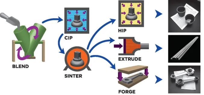
Ti-MMCs used in this study are produced by Dynamet Technology, Inc., and are made of Ti-6Al-4V alloy matrix reinforced with 10-12% volume fraction of TiC particles with irregular shapes and 10-20 µm size. They are usually made near net shape through a process known as CHIP (Cold and Hot Pressing).
The process includes: blending of raw material powders; CIP (Cold Isostatic Pressing), applying a high hydrostatic pressure at room temperature to compact the blended powders in a tool; vacuum sintering at high temperature in vacuum below the melting point to densify the material
and diffuse the powders to form the alloy or MMC; followed by HIP (Hot Isostatic Pressing) which is used to close the small residual porosities and improve the mechanical properties of the products via applying a combination of moderate temperature and hot argon gas pressure.Other traditional metal working processes such as extrusion could be also performed on the CHIP process materials to form the final product.A schematic of the process is shown in Figure 1-1.
Figure 1-1: Schematic of CHIP process used for production of near-net shape components (Dynamet Technology, Inc.)
The mechanical properties of the Ti-MMC used in this study is provided in Table 1-1. Table 1-1: Mechanical properties of Ti-MMC used in this study (Dynamet Technology, Inc.)
Yield Strength Tensile Strength Elastic Modulus Shear Modulus Thermal Conductivity Specific Heat Density 1014 MPa 1082 MPa 135 GPa 51.7 MPa 5.8 W/mK 610 J/kgK 4500
kg/m3 Titanium Alloy reinforced with TiC particles take the advantage of both titanium and ceramics, thus possess superior characteristics such as high strength, high temperature resistance of titanium with an increase in stiffness provided by the ceramic reinforcement (Pramanik et al., 2008). Thus, they are considered as viable materials in various industries
such as aerospace and automotive. Some applications of titanium metal matrix composites are listed below and shown in Figure 1-2:
• Manufacturing structural components of the F-16 jet’s landing gear
• Turbine engine components (fan blades, actuator pistons, synchronization rings, connecting links, shafts, discs)
• Automotive engine components • Drive train parts
• General machine components
Figure 1-2: Some applications of metal matrix composites such as turbine engine blades, space shuttle struts, F-16 landing gear, automotive engine components, and diesel engine pistons Though Ti-MMCs are produced near net shape, finish machining is required to obtain the acceptable surface quality of the parts. However, these materials suffer from poor machinability due to the hard and abrasive nature of the reinforcing particles, in addition to the low thermal conductivity, low elastic modulus and high chemical reactivity of titanium alloy matrix (S Kannan et al., 2006; Nikham, 2014). Severe tool wear and poor surface finish are considered as the most important drawbacks of machining MMCs.
1.3 Chip morphology
The study of chip morphology goes back to the beginning of the 20th century and the investigations of Mallock (Mallock, 1881) and Taylor (Taylor, 1906). Since then chip morphology analysis has been always of interest due to its importance and its influence on the other machining parameters. This study will provide us with the sufficient knowledge of cutting forces, tool wear and surface integrity; therefore, it can be beneficial in optimizing cutting conditions in order to get better surface finish and longer tool life.
Different properties of the workpiece material such as its yield strength, strain hardening, ductility and hardness are responsible for formation of different chip types. For example during machining materials with very high ductility, due to the severe plastic deformation of the chips, long and continuous chips are generated. Whereas in brittle materials such as gray cast iron, lack of ductility, hence insufficient plastic deformation results in the generation of discontinuous or segmented chips (Miracle et al.). Different cutting parameters also affect the formation of chips. Changes in the crack initiation and propagation as well as changes in the shear localization can lead to different chip formation under different cutting conditions. For example during cutting of titanium alloys different chip formation has been observed as continuous chips at low speeds around 50 m/min, segmented chips at speeds around 100 m/min, and shear localized chips at speed of 125 m/min and above (Daymi et al., 2009). Segmented (saw-toothed) chips are generated during turning of titanium metal matrix composites, which belong to the category of cyclic (serrated) chips (R Bejjani et al., 2011). Cyclic chips are defined as “continuous chips with a periodic variation in thickness” and can be classified into four types of wavy chips, segmented chips, catastrophic shear chips, and discontinuous chips (H. A. Kishawy, M. A. Elbestawi, 1997). Segmented chips will affect the surface integrity, it may cause tool wear on the trailing edge of the tool and also it affects the accuracy of machining and the variability of the tool wear data, due to the force fluctuations which are induced (H. A. Kishawy, M. A. Elbestawi, 1997). Brittleness of the workpiece material, instability of the cutting process, periodic crack generation and catastrophic shear instability can be counted as the root cause of the generation of saw-toothed chips (Komanduri et al., 1981; Komanduri et al., 1984; Recht, 1964; M. C. Shaw et al., 1993). During machining MMCs due to the high induced strain rates, creation of adiabatic shear bands is also responsible for the generation of segmented chips.
Adiabatic shear bands are formed as a result of microscopic failure of materials especially for the materials that are exposed to high strain rates. At high strain rates, a change in the homogeneous plastic deformation pattern into inhomogeneous one, induces extensive local heating and as a result material softening. This phenomenon leads to the generation of the localized deformations (Dai et al., 2004). Particles have an important role in generation of adiabatic shear bands. Plastic deformation takes place only in the matrix and the reinforced particles only deform elastically. The smaller particle spacing as a result of the smaller particle size induces higher strain gradient. As mentioned before, strain gradients strongly affect shear banding generation and higher strain gradients lead to the generation of adiabatic shear bands (Rittel, 2009).
1.4 Surface roughness
Surface roughness is one of the most important components of surface integrity. The selection of optimum cutting parameters in order to achieve the required surface quality has been always a challenging matter among researchers. Different factors affect the surface roughness during machining. Cutting conditions, tool characteristics and the workpiece material are among the most important factors.
Tool-particle interactions during machining of MMCs significantly influence the surface roughness of the workpiece material due to the generation of voids and cavities as a result of particle fracture and/or debonding. This interaction is mainly affected by the variation of the feed. If during machining of MMCs the feed is set approximately equal to the particle size, severe surface deterioration will take place due to the particle fracture, particle debonding and particle pull out phenomena (Davim, 2008).
The influence of the feed rate on the surface roughness is reported to be greater than that of cutting speed and volume fraction of particles in machining MMCs (Bhushan et al., 2010). Besides, contradictory effects of feed on the surface roughness have been observed which should be considered. Decreasing the feed can result in better surface finish due to the generation of smaller feed marks. On the other hand severe plastic deformation and probability of material side flow are the consequences of decreasing feed which would lead to the inferior surface finish. This opposing manner has been also reported in increasing the feed during machining of MMCs
showing declining of the surface finish by increasing the feed in to a specific value and then increasing with further raising of the feed (Pramanik et al., 2008).
Cutting speed also has a significant effect on the surface roughness. Better surface finish has been reported during machining of MMCs with higher cutting speeds due to the facile removal of the hard reinforcement particles (Bhushan et al., 2010).
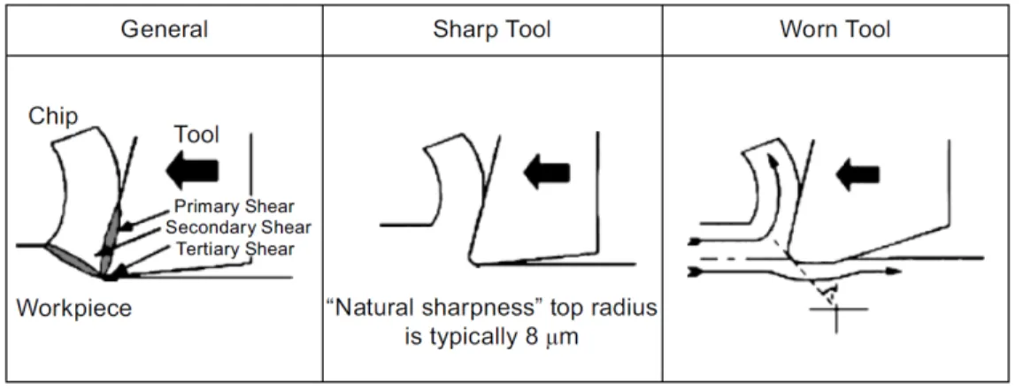
Tool wear during machining also affects the surface roughness. By an increase in tool wear and consequently by an increase in the tool-edge radius, a flat area will be formed along the clearance face. This will in one hand; increase the tool-workpiece contact area and on the other hand; generate high temperatures which both will result in deterioration of surface performance. This effect has been demonstrated in the Figure 1-3 (W. Grzesik, 2010).
Figure 1-3: The effect of tool wear on the surface roughness (W. Grzesik, 2010)
Adhesion property of the tool is also an important factor which affects the surface roughness and should be considered (Bhushan et al., 2010).
Zhang et al. noticed an acceptable surface finish during machining of Al-MMC under a specific feed rate and depth of cut. They also revealed that a further increase in the feed rate and the depth of cut would result in the micro-cracks initiation in the interface of the SiC particles and the aluminum matrix and then gradual formation of macro-cracks on the machined surface. This will result in the deterioration of the surface finish. They also found the SiC grains to be responsible in preventing the dislocation movements and as a result, the macro deformation and dislocation pile-up at the matrix-particle interface (Zhang et al., 2009).
Improvement of mechanical properties of the workpiece material can contribute to better surface finish and surface quality due to declining the plastic deformation and chip bonding (Zhang et al., 2009). MMCs show lower strength in comparison to monolithic materials at all the machining conditions. It can be addressed to the generation of cracks as a result of the presence of particles in the shear plane and tool-chip interface (Pramanik et al., 2008). Strengthening behavior of the MMCs is dependent on the particle size showing higher flow stress with smaller reinforcing particles. This higher strengthening effect can be explained by the higher strain gradient with a smaller particle size (Dai et al., 2004). Strength of the workpiece material in the deformation zones can be affected by the cutting speed and feed via changes in the temperature, strain and strain rate. The reason can be explained by the reduction of work hardening of the MMCs with the temperature raise and its augmentation with the increase of strain rate (Davim, Pramanik, et al., 2008).
1.5 Cutting tools for machining MMCs
Tool life and tool wear tests are regarded as one of the most commonly used criteria for evaluating the machinability. The study will not only reveal the performance of the tool but also the evaluation of the workpiece material can be achieved through the analysis (W. H. Cubberly, 1989).
High hardness, good toughness and wear resistance are the characteristics that are expected from an ideal tool (Astakhov, 2013; Byrne et al., 2003). Hardness of the tool, which is greatly linked to its strength, is considered as a measure to its resistance to deformation. The ability to retain hard at high temperatures (called high hardness) is also considered as an important characteristic of a cutting tool (Astakhov, 2013). Polycrystalline diamond (PCD) and cubic boron nitride (CBN) inserts are the hardest tools in the market.
High fracture toughness of the tool will result in shock resistance, less chipping and fracture of the tool (Astakhov, 2013). As an example, the compromise between the hardness and toughness in cemented carbide tools has ranked them as one of the most useful and successful cutting tools in the various industries (Heath, 2001).
Generally, it is preferred to develop very hard tool materials with increased toughness. Thus, coatings and layered materials are used in order to make a tool with a very hard surface and a
tough core, in order to preserve the high wear resistance of the surface in addition to the high fracture toughness and damage resistance of the core (Dobrzański et al., 2010).
Wear resistance is defined as the ability of the tool in attaining its high integrity and acceptable tool life (Hosseini & Kishawy, 2014). Hung et al. (Hung et al., 1996) compared polycrystalline boron nitride (PCBN) and PCD inserts with WC tools in terms of wear resistance during machining of MMCs. They found that PCBN and PCD tools are superior than WC inserts in the order of magnitude of one and two.
Generally, a balanced combination of mentioned characteristics are expected from a desired tool (Hosseini & Kishawy, 2014). Considering all these factors, different tool materials for cutting of MMCs have been tested till now. PCD tools appear to be the best choice from researcher’s point of view where abrasive wear is the dominant wear mechanism (Heath, 2001). Their abrasion resistance is approximately 500 times more than tungsten carbide (Davim & Astakhov, 2008). During machining of MMCs, abrasive nature of reinforcements induces high abrasive wear on cutting tools, which shows increase with the augmentation of the reinforcement ratio (Bhushan et al., 2010; Songmene et al., 1999). Two-body and three-body abrasive wear are reported to be the main wear mechanisms during machining of MMCs (H. A. Kishawy et al., 2005; Li et al., 2001). Moreover, these particles are harder than most of the common tool materials. However, diamond is exceptionally hard and capable of resisting to the reinforcing particles (Davim, 2002).
PCD tools also inherit superior chemical, physical and mechanical properties such as high strength, resistance to corrosion, low tendency to adhere to the work material, low coefficient of friction and low thermal expansion (Bhushan et al., 2010; Byrne et al., 2003).
Bejjani et al (Bejjani, 2012) found that PCD tools are more suitable for machining of Ti-MMCs, compared to carbide tools in terms of tool life and surface roughness. They found that higher cutting speeds in the range of 170 m/min could be applied with PCD tools, comparing to carbide tools (around 90 m/min). However they found that there is a severe fire hazards above cutting speed of 180 m/min, which should be avoided.
Due to the high cost of PCD tools, researches have been conducted to find the proper cutting conditions which makes it possible to apply other economical tools with the same productivity (Bhushan et al., 2010). Other more cost effective alternatives are CBN, CVD diamond-coated, TiCN/TiN-coated carbide, triple-layer TiC/Al2O3/TiCN-coated carbide and uncoated carbide
CBN inserts show high characteristics such as high hardness and ability to retain a sharp cutting edge, hence preserving the desired surface integrity. They also exhibit high melting point and low friction coefficient and show good chemical stability and wear resistance (Angseryd et al., 2011; Barry et al., 2001; H. M. Lin et al., 2008). Thus, they are proven to be viable alternatives for machining hard-to-cut materials such as metal matrix composites (Aouici et al., 2012; Hung et al., 1998). In terms of hardness, thermal characteristics and fracture resistance, they show superior performance over ceramic and cemented carbide tools, during machining of MMCs (Ravi et al., 2014). It has been reported that CBN tools offer the highest machining performance during machining of Al/SiC MMCs (Ravi et al., 2014). However, there is very limited research performed with CBN inserts for Machining of MMCs, and there is not any study performed on the Ti-MMCs. These were among our motivation for performing a comprehensive study on the different tool wear mechanisms of CBN inserts during machining of Ti-MMCs. In the next section, a literature review on their wear mechanisms are provided.
1.5.1 Tool wear mechanisms of CBN inserts
Cubic boron nitride is the second hardest material after diamond. In general CBN content varies from ~ 50 vol% CBN in “low content CBN” to ~ 80-90 %vol CBN in “high content CBN”, depending on the desired application (Klimczyk et al., 2011). Obtaining a high density CBN is tough due to the strong covalent bonding of B and N and their low self- diffusion coefficients (Klimczyk et al., 2011). Furthermore, CBN is thermodynamically metastable at normal pressures and transforms to hexagonal, graphite like phase with low hardness at high temperatures. Therefore sintering of PCBN under high temperature- high pressure should be performed (Hotta et al., 2008; Klimczyk et al., 2011).
Direct or binder assisted sintering processes are conducted to consolidate the PCBN insert. Superior characteristics of CBN can be achieved through binder assisted sintering processes while the process further allows consolidating the PCBN in comparatively lower temperature and pressure compared to the direct sintering method (Monteiro et al., 2013). Different elements such as metallic elements like Al, Co and Ni as well as ceramic binders such as TiC, TiN and Al2O3
have been recommended for improving the sintering process (Chiou et al., 2013). However, the low melting point of metallic elements limits their usage for high-temperature applications. In addition, the high toughness of ceramic binders will compensate the lower fracture toughness of
CBN. Hence the high hardness of CBN in addition to the high toughness of ceramic binders will contribute to excellent mechanical properties of the CBN inserts (Hotta et al., 2008).
Combination of different tool wear mechanisms have been reported to be involved during machining with CBN inserts (Lahiff et al., 2007).
Chain of physical, chemical and thermo-mechanical phenomena are responsible for the formation of cutting tool wear. High thermal and mechanical loads produced during machining, through generation of considerable amount of cutting heat, pressure and strain, account for the generation of different tool wear mechanisms (Astakhov, 2013). Hard and abrasive reinforcing particles in the metal matrix composites are further detrimental to the cutting tools and will induce higher tool wear.
Flank wear is reported as the dominant wear mechanism during machining of SiC/Al MMCs with CBN, which is highly affected by the particle size. Severe nose and cutting edge fracture was observed during machining with high particle size (110 µm). When machining with small particle size around 30-40 µm, abrasion and adhesion were found to be dominant. Furthermore, an increase in the amount of flank wear was observed with the increase of cutting speed, which was addressed to the built-up edge (BUE) generation and higher adhesion of the workpiece material at higher cutting speeds (Ciftci et al., 2004).
Ding et al. (X. Ding et al., 2005) also found flank wear as the dominant wear mechanism during machining of Al-SiC MMCs with CBN, which occurred jointly with the surface cracking. Intergranular fracture was also observed on the rake face. A significant increase in the adhesion of the workpiece material at high cutting speeds was observed during dry machining. Nonetheless, the application of coolant at low cutting speed reduced the adhesion of the material, but on the other hand, increased the abrasion between the tool flank face and the machined surface. They also found the lowest amount of tool flank wear using binderless PCBN inserts. Yanming et al reported edge and corner breakage of CBN inserts during cutting of Al-SiC MMC with CBN. They found more severe corner breakage and less tool life when machining workpieces with higher volume fraction or coarser sizes of SiC particles (Yanming et al., 2000). Regarding the machining parameters, higher values compared to WC inserts are reported during machining of Al-MMCs with CBN (D. K. Das et al., 2014). Considering the tool geometry, Dabade et al. found lower cutting forces and less surface damage with wiper geometry on the
CBN inserts, which was addressed to higher contact length and as a result higher thermal softening (Dabade et al., 2007).
Other wear mechanisms such as chemical wear (Angseryd et al., 2011; Barry et al., 2001) melt wear (Farhat, 2003) and fracture of the tool binder material (Ezugwu et al., 2005) were also reported during machining with CBN tool but with different materials rather than MMCs:
During machining of steel, abrasion wear was reported as the dominant mechanism at low cutting speeds. Yet, a switch from mechanical wear to chemically driven wear mechanisms, such as diffusion and oxidation wear at high cutting speeds were reported (Kramer et al., 1986).
Angseryd et al. (Angseryd et al., 2011) reported an increase in the chemical wear with the increase in the cutting speed, during machining of hardened steel. They found that at low cutting speeds only the surface of the tool was affected, whereas at higher speeds, an area beneath the wear surface was also involved.
During machining of P20 tool steel, diffusion and melt wear were reported as the dominant and secondary wear mechanisms respectively. Melt wear was described as the formation of low melting point Cr and Mn compounds with the insert material and the consequent removal from the cutting zone (Farhat, 2003).
Ezugwu et al. (Ezugwu et al., 2005) found lower performance of different grades of CBN inserts in terms of tool life, in comparision to uncoated carbide tools during machining of Ti-6Al-4V. This was adressed to the excessive chipping and rapid notching of the CBN cutting edge. They also found that high diffusive wear resulted in the reduction of the bond strength of the insert substrate. More reduction in the tool life was observed with an increase in the CBN content. Luo et al (Luo et al., 1999) found the abrasion of the insert binder material by the workpiece carbide particles as the main wear mechanism during machining of AISI 4340 steel. Furthermore, a protective layer was found on the chip-tool interface, which was a solution of the workpiece material and tool material binder.
Barry et al (Barry et al., 2001) found the chemical tool wear to be the dominant wear mechanism of CBN inserts during machining of BS 817M40 steel. Fragments of oxidized workpiece material were found on the crater surface. Lin et al (H. Lin et al., 2008) reported abrasion wear as the dominant wear mechanism at low cutting speeds during machining of hardened steel. Formation
of a protective oxide layer on the tool face was reported at higher cutting speeds. Transformation of continuous chip to saw-toothed chip under high cutting speeds was also mentions as another phenomenon affecting the wear mechanism of CBN inserts.
1.6 Tool life estimation
Tool life estimation is regarded as one of the most important elements of any machinability analysis. One important reason is the huge costs which are incurred as a result sub-optimal utilization of cutting inserts. It has been reported that only 38% of the time the tools are used up to their full capacity which imposes extra costs as high as $10 billion per year for US industry alone (Umbrello et al., 2004b). The cost could be related to in-service failures such as poor surface quality, scraped parts or machine tool damage, as the result of overestimation of tool life; in addition to the reduction in the overall productivity of the operation and excess machine downtime, due to the underestimation of the tool life. This is even more critical when machining of difficult-to-machine materials such as MMCs (Salonitis et al., 2014).
The first model for tool life estimation is proposed by Taylor (Taylor, 1906) more than hundred years ago, and is still used widely in various machining studies even at the level of national and international standards (Astakhov, 2014). However, the validity of the model for any cutting material rather than carbon steels and high speed steels and for cutting speeds higher than 25 m/min is still questionable (Davim & Astakhov, 2008; Mamalis et al., 2002).
At 1993, Ravinda et al. (Ravindra et al., 1993) described the correlation between the cutting forces and the progressive tool wear and tool failure and introduced it as an indicator of the wear process. Owing to this recognition, several analytical models for tool life estimation and tool wear monitoring were developed later, applying different methodologies (Bhattacharyya et al., 2007; Braun et al., 1999; S. Das et al., 1996; Dimla Snr, 2000; Huang et al., 2007; Lee et al., 1998; Sikdar et al., 2002).
Numerous studies have also been performed by correlating tool wear to different signals such as tool temperature (Mathew, 1989; Wanigarathne et al., 2005), vibration (Dimla Sr et al., 2000; Orhan et al., 2007), surface roughness (de Agustina et al., 2014), power signals (Oh et al., 2004) and optical measurements of tool wear (Gadelmawla et al., 2014) extracted from different sensors such as dynamometers, acoustic emission and accelerometers (de Agustina et al., 2014; Dimla
Snr, 2000). Several tool wear monitoring were also developed using finite element analysis (Xie et al., 2005; Yen et al., 2004).
Although success was claimed in these studies, the random nature of the tool wear was neglected in these model, which may adversely affect their precision (Martin, 1994). Considerable variability of the tool wear data could exist due to various factors such as differences in the physical and mechanical properties of different batches of workpiece and tool materials. During machining of composite materials, significant variation could exist even within a single batch of material as a result of nonhomogeneous distribution of the reinforcing phases. Thus, for this class of material development of models based on the theory of probability is highly recommended. In 1977, DeVor et al. (DeVor et al., 1977), studied the probabilistic nature of the cutting tool life. Afterwards, several models were proposed for the reliability analysis of cutting inserts, implementing different probability distributions of tool failure data such as normal, lognormal and Weibull (DeVor et al., 1977; Hitomi et al., 1978; Mazzuchi et al., 1989; Negishi, 1976; J. G. Wager et al., 1971; K.-S. Wang et al., 2001).
Generally, in a reliability analysis two states are considered for a system which is intended to perform a function: good, if it performs the function; and defective if it is not capable of performing the function. These states are interpreted statistically. Time to failure (TTF), which is the interval between the time at which the system started its function till the moment it failed, is considered as a random variable (x≥ 0), which could have different distributions. If the time to failure possess the distribution of 𝐹 𝑡 = 𝑃 𝑥 ≤ 𝑡 , then the system reliability is:
𝑅 𝑡 = 1 − 𝐹 𝑡 = 𝑃 𝑥 > 𝑡 (2-1)
Thus, F(t) is the probability that the system fails before time t; and R(t) is the probability of not having the failure at least till time t (Papoulis, 1990).
During a machining process, a cutting tool could also have two possible states: an operating state and a failure state. In the operating state machining tool is properly capable of fulfilling the intended machining function. While the failure state, which is considered as an opposing event to the operating state, occurs when the cutting tool is unable to cut properly or when the detriments to the surface outweighs the tool replacement cost. This failure state is usually defined, in terms of permissible maximum tool wear defined on the tool wear curve. The tool wear curve
demonstrates three states called as initial, steady and rapid states. Severe vibration, cutting forces and temperature occur at the third (rapid) state. Thus, tool should be replaced before entering this state in order to avoid detriments to the tool and workpiece. The tool wear at the transition point between the first and second states is often considered as the tool wear criterion (Astakhov, 2006).
Considering the time to failure of cutting inserts as a random variable (DeVor et al., 1977), reliability of cutting inserts could be formulated and used for the investigating the performance of the tools.
Klim et. al. (Klim et al., 1996) developed a reliability model in order to investigate the effect of feed rate variation on the tool life. Furthermore, he developed a tool replacement strategy based on the reliability characteristics of the tool life data (Aramesh et al., 2013). Lin (Lin, 2008) studied the reliability curve variation under different cutting speeds. Rodriguez et al. (Patiño Rodriguez et al., 2010) developped a policy for tool replacement in turning and milling operations based on the reliability analysis. Wang et al. (K. S. Wang et al., 2001) developped a reliability dependent failure rate model for estimating the cutting tool reliability. Rodrigez et al (Patiño Rodriguez et al., 2010) developed the reliability function for the turning and milling operations, and used it to define the changing time of the cutting tools.
Mazzuci et al. (Mazzuchi et al., 1989) introduced proportional hazards model (PHM) in machining for reliability assessments of cutting tools. PHM is an effective model for survival analysis which mostly used in medical science. In tool reliability analysis, this model accounts for aging and cumulative tool wear in addition to the effect of the cutting conditions, which are reflected in the covariates of the model.
Tool wear is highly dependent on the cutting conditions, especially cutting speed and feed rate (Jemielniak et al., 1985). Furthermore, tool wear has an aging behavior, meaning that the probability of failure increases over time during the machining operation. Implementing these effects in the model, PHM stands out above the models introduced even later for tool reliability analysis.
Feng et al. (Feng et al., 2011) developed a PH model for tool reliability assessment, using tool vibration signal feature extraction. Liu et al. (Liu et al., 1996) used a PH model and developed a general formula for tool reliability calculation, assuming a constant parameter values of hazard