HAL Id: hal-01853228
https://hal.archives-ouvertes.fr/hal-01853228
Submitted on 2 Aug 2018
HAL is a multi-disciplinary open access
archive for the deposit and dissemination of
sci-entific research documents, whether they are
pub-lished or not. The documents may come from
teaching and research institutions in France or
abroad, or from public or private research centers.
L’archive ouverte pluridisciplinaire HAL, est
destinée au dépôt et à la diffusion de documents
scientifiques de niveau recherche, publiés ou non,
émanant des établissements d’enseignement et de
recherche français ou étrangers, des laboratoires
publics ou privés.
CANSAT: Multiphysical experimental design of a probe
come-back mission
Justine Gontier, Carlos Hervas Garcia, Joël Bordeneuve-Guibé, Christine
Espinosa
To cite this version:
Justine Gontier, Carlos Hervas Garcia, Joël Bordeneuve-Guibé, Christine Espinosa. CANSAT:
Mul-tiphysical experimental design of a probe come-back mission. 64th IAC - International Astronautical
Congress, Sep 2013, Beijing, China. pp.0. �hal-01853228�
To cite this document: Gontier, Justine and Hervas Garcia, Carlos and
Bordeneuve-Guibé, Joël and Espinosa, Christine CANSAT: Multiphysical experimental design of a
probe come-back mission. (2013) In: 64th IAC - International Astronautical Congress, 23
September 2013 - 27 September 2013 (Beijing, China).
O
pen
A
rchive
T
oulouse
A
rchive
O
uverte (
OATAO
)
OATAO is an open access repository that collects the work of Toulouse researchers and
makes it freely available over the web where possible.
This is an author-deposited version published in:
http://oatao.univ-toulouse.fr/
Eprints ID: 11586
Any correspondence concerning this service should be sent to the repository
administrator:
[email protected]
CANSAT : MULTIPHYSICAL EXPERIMENTAL DESIGN OF A
PROBE COME BACK MISSION
Justine Gontier
ISAE-ENSICA, Toulouse, France, [email protected] Carlos Hervas-Garcia∗, Joel Bordeneuve-Guibe†, Christine Espinosa‡
Abstract
Earth reentry and recovering of a small space probe (typical of a students’ project satellite) set questions related to guidance and control. If the probe is asked to reach a target point with constraints on the landing precision, then other questions related to the foil and to the complete system performance arise. In this frame, the aim of the present work is to design, to build and to operate a decelerator system that is automatically controlled by the satellite probe in the objective to reach an a priori chosen landing point with a required precision. This multiphysics project involves at the same time design and fabrication of the decelerator (parafoil and suspension lines), flight mechanics of the deformable decelerator, guidance and control development, system engineering of the probe development. The project is divided in two similar but distinct projects. The first one called ”small probe" (33 cL / up to 350 g, International Class) aims to improve the complete system global performance with the goal of precise landing and in-flight missions, for a low altitude release configuration. The ”small probe" students’ project aims the French CanSat challenge, an international competition organised in France by CNES and Planète Sciences Association. The second one is to launch a ”big probe" (1 L / up to 1 kg) from a 1/25th scale replica of the Soyouz Rocket developed by a partner student’s team of Samara State Aerospace University (Russia). The latter case aims to test previous developments in more complex and severe release and descent conditions.
I. INTRODUCTION
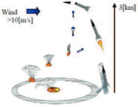
Earth re-entries of small space sample payloads [1, 2] or recovering of high altitude scientific analysis devices are the typical kinds of return application under consider-ation (Figure 1). After atmosphere re-entry of the former both kinds of project need to develop both a reliable auto-matic guidance and control system, and a stable decelera-tor system that can be controlled by the probe.
Figure 1: Flight mission illustration
Stability of the foil is mandatory to get constant or pseudo constant aerodynamic performances during the three phases of the decelerator descent illustrated in Fig-ure 1 : opening and self-stabilization, stable descent, ap-proach and final landing phase. Reliable guidance and control systems are necessary to give the system auton-omy to self-compute position and distance to the target point, and give the control order to the governing actuator. In the case of a small parafoil decelerator systems (small mass of payload and small foil), the extreme thinness and deformability and the foil make it sensitive to external wind amplitude and changes. As a consequence the foil does not keep a permanent shape making difficult its con-trol through the suspension lines. Due to its small weight, the system furthermore suffers high displacements and ro-tations modifications (and sometimes looping!) between two sequenced instants of the control system [3].
Stability of the foil for different sizes has previously been studied by our student team through laboratory wind tunnel experiments [4] and complete systems drop tests from a balloon [5]. Numerical simulations of the fluid-structure interaction between the parafoil and the air dur-ing the stable descent phase have also been studied by partner students’ internships [6] .
∗Carlos Hervas-Garcia, ISAE-ENSICA, Toulouse, France, [email protected]
†Dr. Associate Professor - Department of Mathematics Informatics and Automatic, Université de Toulouse - Institut Supérieur de l’Aéronautique
et de l’Espace www.isae.fr , [email protected]
‡Dr. Associate Professor ISAE Department of Mechanics of Structures and Materials, Université de Toulouse –Institut Clément Ader
Figure 2: Comparison between real and numerical deflec-tion
For the global project further investigations it was shown [7] that the control algorithm had to be improved for low altitude drop tests of a small probe under bal-loon, and that the complete system had to be improved for higher altitude launch. As a secondary objective, it is aimed to challenge our both projects during the French International CanSat championship in August 2013.
The purpose of the present paper is to explain the development strategies and results of the two similar projects called ”small probe" and ”big probe". The small probe is an International Class CanSat device (33 cl up to 350 gr) dropped from a captive balloon. A special solar balloon system has been developed to allow rapid testing and to respect French students operation regulations. The big probe is an Open Class CanSat device (1 L up to 1 kg) launched from a 1/25 th scale replica of the Soyouz Rocket designed, build and operated by a partner student team of the Samara State Aerospace University (Russia).
II. THECANSAT CHALLENGE REQUIREMENTS
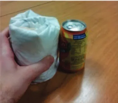
Figure 3: The CanSat International Class compared to a can
The CanSat Challenge consists in the conception of an autonomous device to be dropped from a captive bal-loon at 150 meters high. This device is required to realize 3 technical and scientific missions and respect specifica-tions. Indeed, the volume is typical of a soda can, that is
330 mL, and its mass must be less than or equal to 350 grams.
The principal mandatory missions are precise landing, and atmospheric air environment measurements (pres-sure, temperature, hydrothermal state). Measured data must be transmitted through a real time connection to a ground station. The third mission is up to the team pro-posal.
II.I. ATMOSPHERIC AIR MEASUREMENTS
The CanSat has to be able to make some measures of atmospheric pressure, hygrometry, and temperature. The values of the different parameters are sent in live to the ground station to be analysed, the data transmission are assured by two antennas, an emitter on-board antenna and a receiving one on the ground.
The recording device, coupled with the real time transmission, enables a record of the flight necessary for a data post-treatment. All the data during the flight are stored on a SD card in order to get the results even if there is a transmission problem during the flight.
II.II. PRECISION LANDING
The objective is to reach a target on the ground. This target is positioned in less than 75 meters from the po-sition of the launch of the CanSat. The exact placement is done by GPS coordinates just before the launch. The goal of this mission is to land as near as possible from the target thanks to a piloting sail or a mechanical system of terrestrial transport after parachuting.
II.III. FREE MISSION
The recording device, coupled with the live date trans-mission, enables a record of the flight necessary for a data post-treatment. The video gives information about the sta-bility of the CanSat that could be used to optimise the CanSat’s answers to the request of the servo-motor.
All the data during the flight are stored on a SD card in order to get the results even if there is a transmission problem during the flight.
III. CONCEPTION OF THECANSAT: PROJECT MANAGEMENT
III.I. CONTEXT AND SUMMARY OF PREVIOUS WORKS
Since 2009, our school, ISAE-ENSICA, has been represented in the CanSat France Competition through the former club Budstar. Since summer 2012, the former
Budstar team has become an association called N6K’nSat. This year, we build two CanSat categories, an Interna-tional Class and an Open Class. N6K’nSat was created to promote our study and work on CanSat, and more and more students have participated in the CanSat project. Indeed, ENSICA students have won CanSat France Com-petition every year since 2009 and one Spanish contest .
Different free missions: record in flight paraglide opening and stability, record ground vision to help or complete GPS for the ultimate landing phase. The video gives information about the stability of the CanSat that could be used to optimise the CanSat’s answers to the re-quest of the servo-motor.
Other missions aimed to test the effect of the probe configuration under the foil, either horizontal or vertical, on the global system performance and stability.
III.II. PROJECT MANAGEMENT AND TEAMS
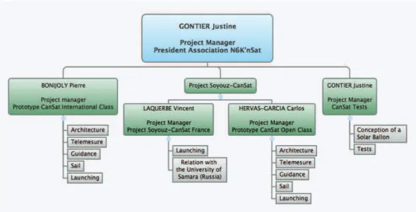
This CanSat project is divided in 3 teams: the proto-type International Class, the project Soyouz-CanSat and the development of a test system, described on Figure 4.
IV. CONCEPTION OF THECANSAT: TECHNICAL DEVELOPMENTS
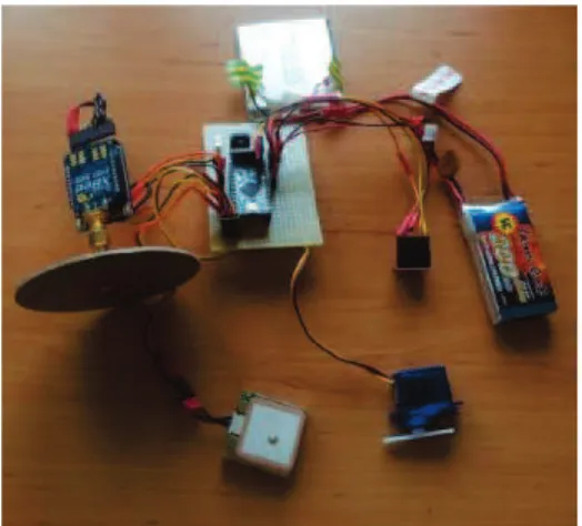
IV.I. THE COMPONENTS
The CanSat is composed by different components to be supplied, to complete its missions. Its on-board elec-tronic system is controlled by a calculator mini Arduino pro, likened to C++ programming software, and supplied by a lithium polymer battery.
The atmospheric sounding is realised by a pressure-temperature captor. The position of the CanSat is given by a GPS EM406A, and the sail is piloted by two servo-motors. The data are sent from an XBee emitter (Figure 5) on the CanSat and an XBee receptor on the ground sta-tion (Figure 6). The recording is done by a camera which could record 45 minutes.
Figure 5: XBee, transmitter in the CanSat
Figure 6: XBee receiver on the ground, linked to the ground station
In order to have the cap followed by the CanSat, the use of an inertial power station has been considered but not realised yet.
IV.II. THE ELECTRONIC CARD
The electronic card allows the connexion between the different components and their alimentation. It is a ”sim-ple face" type and it is realised like other classical electric circuit with copper, light-sensitive resin, epoxy support and protector film. For the conception of the card, we have used the software CAO Eagle.
IV.III. THESTRUCTURE
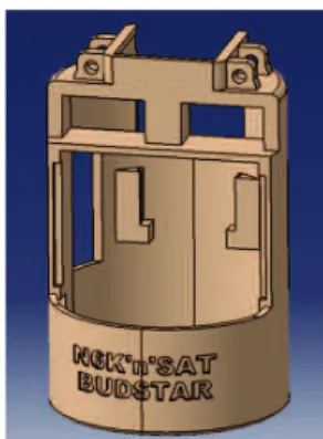
The structure has been realized thanks to the software Catia∗in such a way that the limited volume of the CanSat could be optimised.
Figure 7: Structure of the CanSat by the software Catia
This structure is composed of places for GPS, the XBee emitter and the servo-motors. Fixations have been created to fix the riggings of the parachute. The activated
Figure 4: Organisation Chart
riggings which control the CanSat are fixed on the servo-motor blades. The servo-servo-motors are also placed as far as possible to obtain the maximal deformation of the sail.
Figure 8: The CanSat
IV.IV. THE SAIL
To sustain the CanSat, we use a Nasa ParaWing 5 sail (Figure 9). This kind of sail has the advantage to be built easily and to be modified by being adjusted by the rigging [8, 9].
We use two NPW5 sails. The dimensions and the lengths of the riggings are calculated according to the lift/drag ratio, the mass of the CanSat and the progress speed. This speed has to be at least 5 m/s et the mass is limited by 300 g. The lift/drag ratio is around 2. So, thanks to the computation software ”TW NPW5", the sails have a span around 50 cm and a surface of 0,36 m2.
Figure 9: Nasa ParaWing 5 Sail
V. GUIDANCE ANDCONTROL V.I. PILOTING OF THE SAIL
For the piloting of the CanSat, two configurations have been thought, but no one is optimized. The question of the piloting is not yet completely solved [10].
Vertical configuration
In this configuration, the CanSat turns thanks to a unique servo-motor which attaches the sail. The gravity centre is moved from a referential linked to the sail. Thus, the probe turns.
rig-gings are linked together to the pale of the servo-motor. Horizontal configuration
For this configuration we wanted to reproduce an ar-chitecture based on the one used for parachute or paraglid-ing. In this configuration too, the CanSat moves thanks to the moving of its gravity centre. The difference is that the sail is deformed like the one on a paragliding, pulling the riggings.
In this configuration,the use of two servo-motors, for each side of the sail, is necessary. An other difference is that with this configuration, only one rigging is piloting and the others are fixed to the structure. Nevertheless, in this position, the gravity centre is on the servo-motors axis and so the CanSat has not the wanted performance.
The piloting of the CanSat is still something which has to be improved.
V.II. GUIDANCE OF THECANSAT
To fulfill to the precision landing mission, an algo-rithm has to be developed in two parts, the approach strategy and the finale approach.
The approach strategy
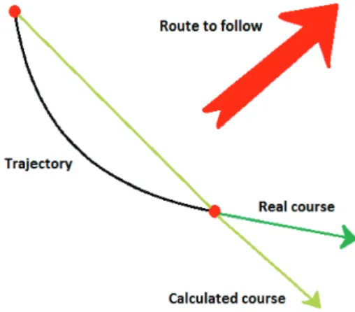
The direction calculated by the Arduino thanks to the GPS coordinates is different from the real direction taken by the CanSat (Figure 10). The GPS measures are taken every 2 seconds and the potential trajectory curve.
Figure 10: Iterative Strategy with computation of the real course and comparison with the route to follow before turning
The principle of the algorithm is to send a command to the motors every two GPS-periods. The command sent to the servo-motors is a proportional gain K multiplied by the direction error :
Motorcommand = K.εCap (1) with
εCap= theoreticalCa p− f ollowedCap (2) The final approach
This strategy consists in measure the distance between the CanSat and the target every GPS-period. As soon as this distance is under 5 metres† the Arduino sends the maximal command to the CanSat which spirals down and stays in the area of the target.If the CanSat is going out of the target area, due to the wind for example, the approach strategy is used again.
Even with those codes, the result is not always good. Indeed, the mass of the CanSat is very low and so it is very sensible to the wind.
V.III. ASSOCIATED CODE
In the aim to pilot the CanSat, a micro-controller Ar-duino V0023 is used for executing in loop the code in C language. All the wished actions on the different CanSat components are done by the Arduino. The GPS coordi-nates are recovered and then analyzed by the code which allows to give the commands to the servo-motors. In the same way, the temperature and the pressure datas are col-lected and analyzed to calculate the height of the CanSat. All those datas are saved in a SD card and sent directly to the ground thanks to the XBee.
The code is started thanks to an umbilical cable which is removed when the CanSat is launched.
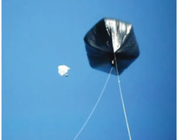
VI. TESTS WITH A SOLAR BALLOON VI.I. CREATION OF THE SOLAR BALLOON
In order to test the piloting guidance of the CanSat, in the conditions of the challenge, the use of a captive solar balloon of 4 meters of diameter is a good solution [11]. Indeed, thanks to the sun ray, the air inside the balloon becomes hotter than the air outside and the ballon begins to ascend. This ballon can ascend to 150 meters with 2 kilograms of load.
A tube in composite has been made to put the CanSat into and to launch the CanSat in a similar way to the chal-lenge.
Nevertheless, this mode of tests is very sensible to the climate, like the temperature and the wind.
VI.II. TESTS OF THECANSAT
Tests at 50 meters have been achieved. The sail of the CanSat opened well. The good response of the com-mand showed that the piloting and the guidance of the CanSat were working. The precision of the piloting guid-ance could be tested. To do that, the CanSat would have to be launched at 100 meters.
Figure 11: Tests of the CanSat with the Solar Ballon
VII. OPENCLASS CATEGORY VII.I. THESOYOUZ-CANSAT PROJECT
One of the natural evolutions of the CanSat project is the Open Class CanSat or, in other words, the CanSat 1Kg. This evolution comes from the initiative of coop-eration between ISAE and the Samara State Aerospace University in Russia, in an act of commemoration of the first french-russian space cooperation.Teams from both universities agreed to develop and integrate a new CanSat into a 1/25th Soyouz rocket replica to compete annually in Open Class Categories of CanSat competitions. This cooperation work requires the integration of the already existing CanSat technology into the launcher constraints. Besides, the redesign and implementation of new tech-nology was necessary in order to respond to the new requirements.
VII.II. MISSIONS’ DEFINITION AND NEW CHAL-LENGES
The missions of the Open Class CanSat are the same as the ones of the International Class CanSat as far as pre-cision landing and atmospheric air measurements are con-cerned. However, the ”big probe" will be launched from the Soyouz rocket at an altitude between 700 and 1000 meters, hence the following adapted missions :
• Real-time telemetry: once the CanSat is ejected from the Soyouz rocket, it will have to transmit data to the ground station. Tough real-time sounding is not required by the competition basis, this achieve-ment could make the difference from other projects. Therefore a great effort has been done to develop a communication subsystem powerful enough to per-form real-time transmission from the very begin-ning of the CanSat flight.
• Comeback: the CanSat will not simply be dropped. One of the challenges of a CanSat project is to build a payload capable of, autonomously, reach a target previously set. For this task the already existing pi-loting and guidance algorithm has been refined and tuned for this new CanSat.
• Integration into the Soyouz: the launcher is meant to climb up to 1 km height and eject at that point the CanSat. It introduces constraints in weight, volume and acceleration forces that the CanSat has to meet. One of the main challenges of this project is the continuous cooperation and work under constraints in what constitutes an authentic system integration project.
VII.III. OPENCLASSCANSAT DEVELOPMENT Structure and parachute
The initial existing CanSat structure was no longer valid. The new CanSat must prove its strength to accel-erations forces close to 12 g at take-off‡as well as strong decelerations at the time of deployment of the parachute or at the moment of impact with the ground. Accordingly, an important redesign and reinforce study of the thermo-plastic structure was held.
Firstly, a finite elements study in SAMCEF§was car-ried out. The 3 most critical phases were modelled for its posterior study: the take-off, the parachute deployment and the impact with the ground. This study revealed the weakest points of the initial concept, designed in CATIA V. Next, this concept was modified in order to strengthen
‡This acceleration is imposed by the launcher §Samcef is a finite elements computation software
the most critic points in terms of load. The final model was achieved after an iterative process of analysis and re-design. Some results of the structural study and redesign work are shown in Figures 16 and 13.
Figure 12: Results of SAMCEF computation
Figure 13: Evolution of the structure computing in Catia
Besides, a new adequate parachute had to be found to make possible the control of the flight. This parachute was chosen regarding its performance and manageability when attached to a 1 kg load. The parachute had been designed, built and tested entirely within the context of a final year work project of ISAE students [4]. This year it has been re-adapted and tested in order to meet the com-petition requirements.
Figure 14: Sail used for the CanSat
Electronic system
Following a logic up-down approach, the open class CanSat system consists in 4 different sub-systems:
• Power subsystem: responsible for providing the proper voltage to each component it has to assure the endurance through the entire mission. Its final configuration is a trade-off between volume-mass and capacity.
• Microcontroller subsystem: The Arduino Pro Mini (based on the ATmega168 electronic board) is the brain and the hub of all the electronics CanSat. It is responsible for the execution of the piloting and guidance code as well as the management of infor-mation between the components and between the CanSat and the ground.
• Peripheral components subsystem: formed by the temperature, pressure and hygrometry sensors, the camera, the GPS module and the servo-motor. This set of components is aimed at either receiving data from the environment and send it to the Arduino or execute the Arduino’s commands.
• Communication subsystem: Dedicated to make possible the real-time data link between the CanSat and the ground station when airborne, several im-provements from previous CanSats were neces-sary. In addition to the Xbee wireless communi-cation modules previously used, the antennae had been conceived and developed specifically for this
project. Regarding the importance of this feature within the Open Class CansSat project, the next point of this article will be dedicated to this sub-system.
Figure 15: Patch antenna model
Figure 16: Results of SAMCEF computation
All this subsystems are assembled in an electronic board with the aim of centralizing the functions around the microcontroller and ease the reparation or substitution in the case of an eventual failure in any subsystem.
Communication Subsystem
One of the most important involvements of the Open Class CanSat project is to adapt to the exigencies of the Russian launcher. Apart from the structural and mechan-ical constraints, the fact of being ejected at 1 Km height implies that, for the success of the missions, the commu-nication must have a range greater than 1000 m.
Establishing a simple equation for the link budget
be-tween the CanSat and the ground station it shows that: Prec= λ2 4πR2GEmaxGRmaxPin (3) hence, Rmax= λ 4π r GEmaxGRmaxPin Prec (4) Being restricted for the public band frequency be-tween 2.4 and 2.5 GHz (and hence the wavelength), as well as for the power emitted (by the French electromag-netic emission regulations) and the power received (de-pendent on the receptor technology), the maximum range can only be increased by increasing either GEmax or GR-max of the onboard and reception antennae respectively or both. Thereby one of the main tasks of this project has been to think out a technological solution to this problem that allowed increasing the emission and reception gains while adapting to the volume, mass and shape constraints. Amongst the limited technological solution, the patch antenna seemed to be the most appropriate. It is a sim-ilar technology to the one used in modern GPS recep-tors. Three different antenna models were theoretically conceived. Some of the principal pursuit features of these antennae were:
• Radiation pattern as roundest as possible, with the maximum gain increment within a beam of 120o from the vertical axis of the CanSat.
• Resonance frequency of the antenna on the public band frequency together with an optimal adaptation of the transmission line to minimize the reflection losses.
• Circular polarization of the electromagnetic field so as not to depend of the CanSat orientation with re-spect to ground.
For its theoretical validation, a complete computa-tional simulation in HFSS¶ was carried out. Later, these antennae were fabricated and tested to verify and validate its technical specifications.
Piloting and guidance Strategy
At this point, the Open Class CanSat reused the exist-ing pilotexist-ing and guidance strategy for the CanSat vertical configuration. A few changes on the proportional gain and initial setup were necessary to adapt the already de-veloped law to the 1kg CanSat. These changes showed to perform adequately.
Project management and cooperation work with the Russian Team
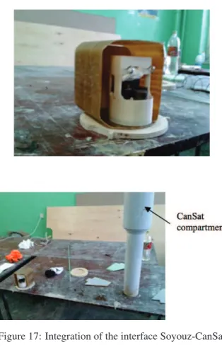
The participation in the CanSat competition together with the required continuous communication with the Russian Team was responsible for a demanding commit-ment of organization. A regular monthly call as well as daily mailing with them ensured the success of this cooperation. In addition a representative of the Open Class CanSat ISAE team went to the Russian facilities in Samara to finalize the integration of the interface Soyouz-CanSat.
Figure 17: Integration of the interface Soyouz-CanSat
VIII. RESULTS OF THECANSATCHALLENGE ACKNOWLEDGEMENTS
This work has been partially funded by the following organisms: ISAE SUPAERO Association, CNES (French Space Agency), ISAE Direction Formation ENSICA. All the students and permanent people of ISAE who con-tributed to this project are sincerely thanked for their deep help. A special mention is due to the original ENSICA team Budstar Association for their friendly support.
REFERENCES
[1] J.E. Benton, M. Murbach, O. Yakimenko, P.Papadopoulos, "Development of precision parafoil flight at high alitude for sample return applications", Poster at 9th International Planetary Probe Workshop, Toulouse (France), June 2012 [2] K. Ramus , M. Murbach, K. Boronowsky, J. Benton,
C. Gonzalez, D. Atkinson, "Characterizing an exper-imental decelerator for delivering Nano-sat payloads to planetary surfaces", Poster at 9th International Planetary Probe Workshop, Toulouse (France), June 2012
[3] M. Archen, J. Badier, A. Basset, S.-K. Courty-Audren, L.-P. Minot, "Cansat", Engineering School Student Project, Toulouse (France), June 2010 [4] S. Ben Yamin, A. Guevezov, T. Loiselle,
”Caractéri-sation de voilures souples pour concours Cansat", Engineering School Student Project, Toulouse (France), June 2012
[5] R. Castellon, R. Chesneau, M. Di Luca, J. Encon-nière, J.-E. Pierré, "CanSat", Engineering School Student Project, Toulouse (France), June 2012 [6] Juan Loukota, "Fluid Structure Interaction of a
Parafoil", ISAE, March 2012
[7] J.-E. Pierré, R. Castellon, R. Chesneau, "CanSat: multiphysics experimental design of a probe come back mission", 9th International Planetary Probe Workshop, Toulouse, France, 16th-22nd June 2012 [8] K. Hiraki, M. Inoue, "development of autonomous
flight systems with small parafoil", 20th AIAA Aerodynamic Decelerator systems Technology Con-ference and Seminar, Seattle (US), May 2009 [9] M. Bayada, B. Lafaille, D. Le Goff, Y. Leurent,
"Etude de la Pilotabilité d’un Parafoil", Engineer-ing School Student Project, Toulouse (France), June 2011
[10] A, Belnou, P. Bonijoly, X. Guihot,V. Migeon, "CanSat : Pilotage Guidage", Engineering School Student Project, Toulouse (France), June 2013 [11] J. Chevalier, J. Gontier, M. Sachot, A. Schmider,
"Développement d’un moyen d’essais", Engineer-ing School Student Project, Toulouse (France), June 2013