Analysis of human spatial perception during lunar landing
The MIT Faculty has made this article openly available. Please share
how this access benefits you. Your story matters.
Citation
Clark, T.K. et al. “Analysis of human spatial perception during lunar
landing.” Aerospace Conference, 2010 IEEE. 2010. 1-13. Copyright ©
2010, IEEE
As Published
http://dx.doi.org/10.1109/AERO.2010.5447026
Publisher
Institute of Electrical and Electronics Engineers
Version
Final published version
Citable link
http://hdl.handle.net/1721.1/66194
Terms of Use
Article is made available in accordance with the publisher's
policy and may be subject to US copyright law. Please refer to the
publisher's site for terms of use.
Analysis of Human Spatial Perception during Lunar
Landing
Torin K. Clark, Alexander J. Stimpson, Laurence R. Young, Charles M. Oman Man-Vehicle Laboratory, Massachusetts Institute of Technology
77 Massachusetts Avenue 37-219, Cambridge, MA 02139 (617) 253-7758 torin@mit.edu
Kevin R. Duda
The Charles Stark Draper Laboratory, Inc. 555 Technology Square, Cambridge, MA 02139
(617) 258-4385 kduda@draper.com
Abstract—Crewed lunar landings require astronauts to
interact with automated systems to identify a location that is level and free of hazards and to guide the vehicle to the lunar surface through a controlled descent. However, vestibular limitations resulting from exposure to lunar gravity after short-term adaptation to weightlessness, combined with acceleration profiles unique to lunar landing trajectories may result in astronaut spatial disorientation. A quantitative mathematical model of human spatial orientation previously developed was adopted to analyze disorientation concerns during lunar landing conditions that cannot be reproduced experimentally. Vehicle acceleration and rotation rate profiles of lunar landing descent trajectories were compiled and entered as inputs to the orientation model to predict astronaut perceived orientations. Both fully automated trajectories and trajectories with pilot interaction were studied. The latter included both simulated landing point redesignation and direct manual control. The lunar descent trajectories contain acceleration and rotation rate profiles producing attitude perceptions that differ substantially from the actual vehicle state. In particular, a somatogravic illusion is predicted that causes the perceived orientation to be nearly upright compared to the actual vehicle state which is pitched back. Furthermore, astronaut head location within the vehicle is considered for different vehicle designs to determine the effect on perceived orientation. The effect was found to be small, but measureable (0.3-4.1 degrees), and larger for the new Altair vehicle design compared to the Apollo Lunar Module.12
TABLE OF CONTENTS
1.INTRODUCTION ... 1
2.COORDINATE FRAME DEFINITION ... 2
3.ALHATLUNAR LANDING TRAJECTORIES ... 2
4.SPATIAL ORIENTATION AND ILLUSIONS ... 5
5.OBSERVER MODEL ... 6
6.METHODS ... 7
7.RESULTS ... 7
8.DISCUSSION AND CONCLUSIONS ... 10
1 978-1-4244-3888-4/10/$25.00 ©2010 IEEE 2 IEEEAC paper#1183, Version 1, Updated 2009:10:26 ACKNOWLEDGMENTS ... 11
REFERENCES ... 12
BIOGRAPHY ... 12
1. INTRODUCTION
Crewed lunar landing will require astronauts to continuously monitor and interact with the automated systems in order to bring the vehicle down to a safe and suitable landing point through a stable, controlled descent. This will require the astronauts to collaborate with the automated systems to indentify a location that is level and free of hazards and make adjustments to the descent trajectory and touchdown point through landing aim point re-designation or through direct manual control. Like pilots of any vehicle, the astronauts will need to maintain a geographic and terrain awareness as well as a sense of the vehicle attitude and velocity. However, the unique environment experienced by astronauts during a lunar landing may lead to spatial disorientation. In particular, the presence of lunar gravity following short-term adaptation to weightlessness, extreme sun angles, lunar surface reflectivity, absence of any atmosphere, and dust blowback from the descent engine may interfere with the ability to perform a safe and precise landing.
One of the concerns in the design phase that might be overlooked is how the astronaut’s head location relative to the lunar landing vehicle center of mass (COM) will affect perceived orientation. In the current design of the next generation lunar landing vehicle, Altair, the vehicle increased size will locate the astronauts well above the vehicle COM. The angular velocity and angular acceleration of the vehicle will produce centripetal and tangential accelerations that will be experienced by the astronauts when they are not near the COM. They are likely to influence the astronaut’s perceived orientation and may be disorienting.
Spatial disorientation during lunar landing could be critical. Understanding the types of spatial disorientation that are likely to occur during a lunar landing could guide the design
of countermeasures such as spatial orientation and situational awareness displays in the cockpit.
2. COORDINATE FRAME DEFINITION
The standard reference frame for pilot orientation is a right-handed coordinate system shown in Figure 1. The frame is fixed to the center of the head. The respective components of linear acceleration and angular velocity are also shown. While the astronauts could still be moving their heads within the vehicle to look at different displays or out the window, this analysis is restricted to the case that the only motion that the astronauts are experiencing is that due to the vehicle motion. The head fixed coordinate frame is therefore assumed identical to a vehicle fixed coordinate frame. This head fixed coordinate frame is used for providing inputs and analyzing the outputs of the spatial perception model used in this paper.Figure 1: Head Fixed Coordinate Frame Definition
3. ALHAT LUNAR LANDING TRAJECTORIES
Traditionally, lunar landing trajectories have been divided into a series of phases (Figure 2). The landing trajectory begins approximately15 km from the surface when powered descent initiation (PDI) begins. There follows an automated 400-600 second braking burn to slow the vehicle, removing it from orbit and beginning the descent to the surface. The vehicle then rotates in the pitch-over maneuver to provide the astronauts and sensors view of the landing zone to inspect for hazards and locate suitable landing points. This approach phase is when the astronauts will likely perform much of their interaction with the automated systems. Lastly, the terminal descent phase and touchdown are when the vehicle descends vertically and lands on the lunar surface.Figure 2: Lunar Landing Phases [22]
During the Apollo missions, the astronauts had specific roles during each mission phase of the landing [1,2,3]. Throughout the braking phase, their primary responsibility was to monitor the guidance system. The astronauts were faced down toward the lunar surface such that they could measure the times between landmarks passing through their window to estimate velocity. This was used to doublecheck that the automated guidance system was functioning properly. During the approach phase the astronauts would visually scan the landing area to locate a suitable landing point (LP). Missions were planned such that the sun would illuminate the landing zone without providing glare on the windows of the Lunar Module (LM). During the approach phase, as the astronauts surveyed the landing zone, they could adjust the LP through the digital computer using a hand manipulator. The computer then would provide a numerical readout of the new LP location, which could be viewed by the astronaut through the window by aligning his line-of-sight with a grid marking system on the window. For the astronauts to successfully operate during the approach phase it was particularly critical that they maintain spatial and geographic awareness. Spatial disorientation could result in poor landing performance and decreased safety. Finally during the terminal descent phase, in all six Apollo landings, the Commander took over manual control in a rate control attitude hold (RCAH) mode, similar to traditional helicopter controls, to fly the vehicle down to the surface. It is essential during this phase that the pilot has a correct sense of vehicle orientation in order to operate the controls precisely. During the Apollo landings, the landing site and time were chosen such that there were minimal known hazards, and to allow for the pilot to be able to clearly see the hazards. For the future lunar landings this requirement has been changed such that landings can be made at any location at any time [4]. This includes landings with very limited lighting or extreme sun angles. It will be even more difficult for the pilots to maintain awareness of the surrounding features as well as spatial orientation. Display and sensor countermeasures will be essential to assist the pilot in avoiding disorientation.
NASA’s autonomous landing and hazard avoidance technology (ALHAT) program is currently developing a guidance, navigation, and control (GNC) system as well as hazard detection and avoidance algorithms for precision
lunar landing [20]. As part of this project, studies have been conducted analyzing the trade space of potential lunar landing trajectories [5, 6]. Of particular importance in the trajectory trade space are the magnitude of the deceleration during the braking phase, the trajectory angle, and the slant range. Slant range and trajectory angle are defined in Figure 2 at the particular point in time after the pitch-over maneuver occurs, and the beginning of the approach phase and hazard detection and avoidance (HDA) begins. Each trajectory within the trade space, contains a time history of important vehicle parameters such as linear acceleration, angular velocity, and orientation relative to the lunar surface. While some of the trajectories within the trade space are extreme, others are similar to the trajectories used for Apollo or are the ALHAT baseline trajectory.
Figure 3: ALHAT Trajectory Trade Space [6]
The trade space shown in Figure 3 has the dimensions of trajectory path angle, slant range, and acceleration profile. The numbers of particular trajectories of interest are shown on their respective blocks. The ALHAT baseline trajectory, number 050, is used here as an example trajectory. The 3-2-1 roll-pitch-yaw Euler angles are shown for the vehicle during the ALHAT baseline trajectory, 050.
Figure 4: Vehicle Orientation Euler Angles for ALHAT Trajectory 050
As the maneuver is nearly entirely in pitch, the yaw and roll angles of the vehicle remain near zero during the entirety of the trajectory. On the other hand, the pitch angle varies significantly during the trajectory. The pitch angle begins at -88 degrees such that the astronaut is flat on his back, feet
toward the direction of motion. During the braking burn, the vehicle slowly pitches upright to approximately -55 degrees. The vehicle then rapidly rotates up during the pitch-over maneuver, followed by the approach phase, which maintains approximately a -10 degree pitch angle. Finally, during terminal descent, the vehicle rights itself and descends vertically to touchdown. Figure 5 shows the vehicle angular velocity during the trajectory.
Figure 5: Vehicle Angular Velocity for ALHAT Trajectory 050
Figure 5 shows the vehicle angular velocity in head fixed coordinates as defined in Figure 1. As was seen earlier in Figure 4, there is minimal rotation about the x, and z head fixed directions and most of the rotation occurs in pitch, about the y head axis. The slow and steady rotation during the braking burn seen in Figure 4 is evident in Figure 5 with a rotation of approximately 0.1 degrees/second. However, during the pitch-over maneuver the rotation is more aggressive. Notice that at the end of the pitch-over maneuver, there is actually a brief negative rotation caused by the gimbal motion of the descent engine [21]. This results in a brief extreme angular acceleration which could produce disorientation as will be mentioned. Finally, there is a smaller angular velocity spike at the end of the approach phase as the vehicle pitches to upright prior to terminal descent. Figure 6 shows the vehicle accelerations in head fixed coordinates.
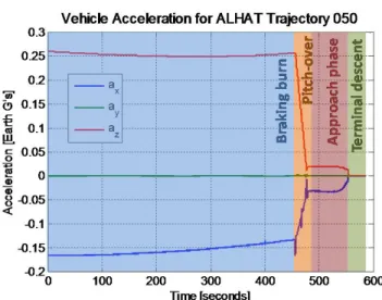
Figure 6: Vehicle Acceleration for ALHAT Trajectory 050
At the beginning of the trajectory, the astronauts are on their backs, so the +x coordinate is pointing up away from the lunar surface. The negative x acceleration is due to the vehicle slowing and falling out of orbit toward the moon, and is nearly equal to the acceleration due to gravity on the moon. The positive z acceleration is due to the acceleration from the descent engine thrusting and slowing the vehicle. During the course of the braking burn the vehicle slowly pitches over, causing a larger portion of the acceleration due to gravity to shift from the x direction to the z direction. During pitch-over the vehicle changes orientation quickly. As the thruster becomes pointed nearly opposite the direction of gravity, the forces partially cancel, and the accelerations become smaller. Also, note that during pitch-over there are some acceleration spikes due to the rapid change of vehicle orientation and the gimbal motion of the decent engine. These may provide stimuli that could result in spatial disorientation. Once the vehicle is upright for terminal descent the descent thruster is pointed opposite the direction of gravity, and there are essentially no accelerations. As will be further discussed, the vehicle angular velocities and accelerations seen in Figure 5 and Figure 6 from the ALHAT trajectory will be used as the inputs to the spatial orientation model to determine the astronaut’s perceived orientation.
While the ALHAT trajectories are useful in studying the autonomous landings, for manned missions the astronauts can, and probably will, make control inputs to the vehicle that influence the vehicle trajectory. As discussed previously, during Apollo the astronauts could influence the landing trajectory by either making landing point redesignations or by taking manual control in a RCAH mode. It is likely that the Altair vehicle will similarly allow the astronauts to control the vehicle in at least these two methods. We used a simulator to capture trajectory information from two different trajectories of interest beyond the automated ALHAT trajectories. In the first case a typical ALHAT trajectory is flown automatically down to an altitude of approximately 1,500 feet at which point a
simulated astronaut redesignation is made. This relocates the landing point from nearly beneath the vehicle to approximately 280 feet away in a direction nearly directly left of the vehicle or in the +y direction. The LP redesignation only affects the later portions of the trajectory, so the entirety of breaking burn portion is not presented in Figure 7.
Figure 7: Vehicle Orientation Euler Angles for Redesignation Trajectory
Figure 7 differs from Figure 4, in that the trajectory includes a simulated LP redesignation. The braking burn for this trajectory is nearly identical to the ALHAT baseline trajectory. The pitch-over maneuver is very similar, except in this particular trajectory the vehicle pitches to essentially vertical prior to the approach phase corresponding to an ALHAT trajectory with a trajectory approach angle of 90 degrees. In Figure 7, the LP redesignation occurs at approximately 500 seconds into the trajectory, when the vehicle is in steady hover. The translational motion is accomplished by first a strong roll to the left to build up horizontal velocity, and then a strong roll to the right to null out this velocity, as seen in the roll angle in Figure 7. For the redesignation trajectory, the exact vehicle motion is determined by the ALHAT guidance algorithm, while the final LP is determined by the astronaut.
The second method by which the astronaut might alter the trajectory is through manual control of the vehicle attitude through the RCAH control mode. To study an example trajectory which includes manual control, a fixed base lunar landing simulator was used, where an actual pilot took manual control at approximately 1500 feet. The pilot first commanded an extreme roll maneuver, and then attempted to correct, null the velocity, and land the vehicle successfully. The orientation of the vehicle during the later portion of this trajectory is shown in Figure 8.
Figure 8: Vehicle Orientation Euler Angles for Manual Control Trajectory
Following the ALHAT baseline trajectory, after the pitch-over maneuver at approximately 1,500 feet altitude, the pilot takes over manual control of the simulation. Initially there are no attitude inputs, as the pilot is arresting his descent velocity. However, at the dashed black line in Figure 8 an extreme roll maneuver is made by the pilot that corresponds to a full stick deflection. This stick input is held until the vehicle orientation reaches approximately 45 degrees of roll tilt, and then the pilot attempts to null the significant horizontal velocity in the +y direction with an extreme roll in the opposite direction. This was followed by a series of orientation inputs attempting to settle the vehicle into a hover. Due to the manual control requirements of the RCAH mode, it is very challenging for the pilot to hold a true hover, and any small tilt angle results in the slow build up of horizontal velocity. The distinction between the approach phase and the terminal descent phase, which is usually characterized by entering a horizontal hover and steady vertical descent, is consequently not as clear as for the automated trajectories. As seen in Figure 7 and Figure 8, the resdesignation and manual control trajectories can contain more extreme attitude maneuvers, particularly during the approach phase, which might lead to disorienting illusions.
4. SPATIAL ORIENTATION AND ILLUSIONS
Spatial orientation refers to the one’s perception of body position relative to a reference frame, in this case the surface of the moon. Spatial disorientation (SD) is traditionally defined as a “failure to correctly perceive attitude, position, and motion” of the vehicle [7]. There are many factors that influence SD, but the cause is always an inability to properly integrate and interpret sensory signals. In some cases, the signals may be conflicting while in others the signals might be ambiguous. For example, the body’s gravireceptors, including the otolith organs of the vestibular system, respond to both gravity and linear acceleration. Thecentral nervous system must disambiguate gravireceptor signals, and determine the component due to angular and linear motions of the body. The way in which the nervous system does this is influenced by many factors, but is not random, and can be quantitatively modeled. One such model [8, 9], was used in this study.
Other than visual cues the primary sensory system used in human spatial perception is the vestibular system. The vestibular system is physically located in the inner ear and consists of two different sensory organs, the semicircular canals and the otolith organs. Over the majority of the frequency range, the semicircular canals measure angular velocity and the otolith organs measure the gravitoinertial force (GIF) as defined in Equation 1. From these two cues, as well as cues from other sensory sources such as visual or proprioceptive cues, the central nervous system (CNS) estimates orientation.
While there are many different types of spatial disorientation illusions, one that is particularly important for the lunar landing task is the somatogravic illusion. This illusion arises due to the fundamental ambiguity between gravity and linear acceleration the otolith cue provides to the CNS. As defined in Equation 1, the GIF vector is the difference between the gravity vector and the head acceleration vector.
a
g
f
−
=
(1)Since the otolith organs do not measure either gravity or acceleration directly, it is ambiguous whether a rotation in the GIF vector by a given angle, θ, is due to a change in the orientation of the head with respect to gravity or due to head acceleration. This is the basis of the classic tilt-translation, or somatogravic illusion ambiguity seen in Figure 9.
Figure 9: Tilt Translation Ambiguity
In the translation case, the head is accelerated forward, resulting in the GIF vector rotating backward, however in the tilt case the nearly same effect is created in the GIF when the head is pitched back. The only difference is the magnitude of the GIF vector, which is usually small and not sensed. Thus the signal being measured by the otolith
organs can be produced by two very different stimuli. This ambiguity can cause the CNS to interpret translation accelerations as tilt maneuvers and vice versa, resulting in errors in spatial orientation estimation.
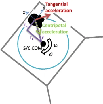
Additional linear accelerations will be experienced by the astronauts during verhicle rotation if the head location is not at the vehicle center of rotation, usually the center of mass (COM). In order to accommodate a larger crew, the Altair vehicle design is much larger than the Apollo Lunar Module (LM) vehicle. One of the consequences of this is that the pilot astronaut’s position within the vehicle will be far above the vehicle COM. As a result, while the head fixed coordinate frame is still assumed to maintain the same orientation as the vehicle fixed coordinate frame, there is a steady offset between the origins of these two frames. This offset between vehicle COM and astronaut head location expose the astronaut to additional tangential and centripetal acceleration during vehicle rotation.
Figure 10: Head Location Offset from Vehicle COM
Figure 10 shows the simplified two dimensional case where the y component of the head fixed coordinate frame is ignored and the angular motion is purely about an axis that is perpendicular with the frame of the paper. The astronaut’s head location is above and in front of the spacecraft center of gravity (S/C CG) by distances rz and rx,
respectively, resulting in an offset difference, r. Vehicle rotations produce angular velocities,
ω
, and angular accelerations,ω
, about the S/C CG. The result is tangential accelerations and centripetal accelerations as defined in Equations 2 and 3.r
a
tan=
ω
×
(2)r
a
T cent
=
ω
ω
(3)These accelerations will be present at the head location in addition to the vehicle accelerations. Due to the somatogravic illusion discussed above, head accelerations can be misinterpreted as tilt motions, so the offset between the vehicle COM and the head location can be responsible for misperceptions of orientation.
5. OBSERVER MODEL
Vestibular neuroscientists have developed quantitative mathematical models for semicircular canal and otolith function, eye movements, and CNS estimation of orientation perceptions [10]. Borah [11] suggested that the CNS functions were analogous to a Kalman optimal estimator when combining sensory cues, and introduced additional dynamics into vestibular responses due to these central processes. CNS observer-based models for semicircular canal-otolith interaction have been developed [9] and have since been elaborated by others [8,13-16] to successfully model canal-otolith cue interaction for a variety of motion inputs. Within these models the general framework is defined theoretically and then the set of gains is adjusted to help the model fit experimental test cases [8, 17, 18].
One of these quantitative mathematical models of semicircular canal and otolith function, Observer [8, 14], has been adapted to predict the perceived orientation of an astronaut during candidate lunar landing trajectories. The basic model structure is shown in Figure 11.
Figure 11: Vestibular-Only Observer Model [8]
The Observer model seen in Figure 11, at its simplest level requires discrete time series inputs of linear acceleration and angular velocity, to the otolith (OTO) and semicircular canal (SCC) models, all in a head fixed frame. Visual inputs were not included for this analysis. It then processes these inputs with models of the dynamics of the otolith and semicircular canal function and integration using an estimator based feedback design to yield a prediction of perceived orientation. The model has been implemented using MATLAB®/Simulink® [8] to allow for processing of actual quantitative inputs.
6. METHODS
The simulations were performed by taking the time series of linear accelerations and angular velocities in head fixed coordinates from candidate ALHAT trajectories using the Altair LDAC-2 vehicle model and using them as inputs to the Observer perceived orientation model. The sample frequency was 40 Hz. Additionally, the Simulink® model interpolates between the sample points in an effort to improve numerical integration. For these simulations it is assumed that there are no visual cues provided to the subject, so that orientation perception is dependent only on vestibular function. While visual cues normally play an important role in orientation perception, during the majority of the trajectory, up until near touchdown, the out-the-window visual cues will provide little information regarding the orientation of the vehicle. A small out-the-window-view of the stars passing by will play a minor role in orientation perception, and as a result, astronauts will be forced to depend significantly on their vestibular system and the cockpit displays. For each of the simulations performed in this paper, the gains were determined from data from simple human perception experiments [8, 17]. The model represents a passive observer, and therefore does not incorporate knowledge of the sensory consequences of the pilot’s or vehicle’s control inputs. The magnitude of gravity experienced at the vehicle altitude increases by approximatley 2.5% as the vehicle desecends from PDI to touchdown and was included in the model.
The ALHAT trajectory trade space has three dimensions: braking burn magnitude of deceleration, slant range, and trajectory angle as defined in Figure 3. The trajectories begin a few seconds prior to the initiation of the braking burn and run until touchdown. This usually results in a 700-800 second trajectory. The vehicle begins tilted back slightly more than 90 degrees with the descent engine pointing downrange as shown in Figure 2. Once the burn begins, the vehicle slowly pitches upright during the braking burn until the astronauts are flat on their back and then tilted back by less than 90 degrees. One of the measures being used to measure orientation is the 3-2-1 yaw-pitch-roll Euler angles. This set of orientation parameters has a singularity when the second angle, in this case pitch, crosses +/- 90 degress. Unfortunately, this occurs during the lunar trajectories right after the braking burn is initiated. Since the braking burn is fairly consistent, this first portion of the trajectory prior to crossing a pitch angle of -90 degrees is truncated. Thus each of the trajectories begins at an orientation of -88 degrees pitched back.
To determine the effect of astronaut head location on perceived pitch angle we compared the time series of perceived pitch angles to those assuming a head location at the vehicle COM. The maximum difference is then recorded as the single quantity to represent the magnitude of the effect of different head locations. The values for rx and
rz defined in Figure 10 were approximated for the Altair
LDAC-2 design, as well as for the Apollo LM, and Lunar Landing Research Vehicle (LLRV) as given in Table 1.
Table 1: Head Location Assumptions for Vehicles
rx [meters] rz [meters] r [meters]
Altair LDAC-2 3.2 0.9 3.3
LLRV 0.9 1.2 1.5
LM 1.8 2.4 3.0
At each head location considered various different types of trajectories from the ALHAT trade space were analyzed. Of note are ALHAT trajectory 050, which is the ALHAT baseline trajectory, and ALHAT trajectories 037 and 038, which were the trajectories within the trade space which most closely fit the Apollo trajectories in braking burn, slant range, and trajectory angle parameters. The remaining trajectories where chosen to represent the extremes of the ALHAT trade space in combinations of braking burn acceleration, slant range, and trajectory angle.
7. RESULTS
A sample trajectory, the ALHAT baseline trajectory 050, is analyzed below.
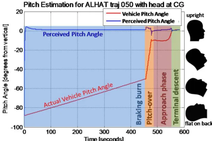
Figure 12: Pitch Angle Estimation for ALHAT Baseline Trajectory with Head at Vehicle COM
Figure 12 shows the vehicle pitch angle and the astronaut’s estimated pitch angle as functions of time. The head figures on the right show the approximate head orientations that correspond to the pitch angle scale on the left. The critical result shown in Figure 12 is that, while the vehicle pitches forward by about 90 degrees, the astronaut’s perceived pitch angle remains approximately 0 degrees through the entire trajectory. They feel as though they are upright with respect to the lunar surface, since the GIF is aligned with their body. Other than a few small deviations during the pitch-over maneuver, the model predicts that the astronaut feels upright, even when he begins flat on his back. This is remarkable, however not surprising. The cause of this drastic incongruency between perceived and actual orientation is a form of somatogravic illusion. The
descent thruster on the vehicle is constantly thrusting in a direction that is approximately down out the bottom of the vehicle, creating an acceleration vector in the direction of the +z axis. To better understand this effect, see Figure 13.
Figure 13: Somatogravic Illusion during Descent
In Figure 13, the vehicle is pitched at a certain angle during descent with the astronaut’s head fixed within the vehicle at the vehicle COM. In the inertial reference frame, there are two forces acting on the vehicle: gravity (mg) and the thrust (T) from the descent engine. Summing these forces and dividing by the vehicle mass (m), yields the direction of the acceleration (a). The direction of the GIF vector (f) is the difference between the gravity vector (g) and the acceleration vector. The GIF vector is exactly aligned with the body axis of the vehicle or the -z axis. The otolith organs sense the driection of the GIF vector, and the CNS interprets this as the direction of gravity. The result is the misperception of being upright throughout the trajectory. While Figure 13 shows the vector addition for a particular pitch orientation, the effect holds throughout the trajectory. The perceived orientation is shown below for the LP redesignation trajectory first shown in Figure 7.
Figure 14: Orientation Estimation for Redesignation Trajectory
Only the roll and pitch Euler angles are shown in Figure 14; yaw angle remains nearly zero throughout the portion of the trajectory shown. As was seen for the automatic ALHAT landing, early in the trajectory the astronaut perceives himself to be upright despite being significantly pitched back. This again is due to the somatogravic illusion induced by the profile of the descent engine as shown in Figure 13. This underestimation illusion angle can also be seen in the roll angle maneuver done during the LP redesignation. In fact, during part of the maneuver the direction of the roll angle is estimated to be opposite of the actual vehicle orientation. This is the result of the gimbal of the descent engine during this maneuver. It creates an acceleration profile that rotates the gravitoinertial force in the opposite direction to the way the gravity vector is rotating at certain parts of the maneuver. As the gravitoinertial force can be misinterpreted by the CNS to be the direction of gravity, the roll angle direction is misinterpreted.
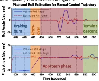
Figure 15 shows the perceived orientation for the manual control trajectory first introduced in Figure 8.
Figure 15: Orientation Estimation for Manual Control Trajectory
As seen in the previous trajectories, the somatogravic illusion that is present at the beginning of the trajectory exists here as well. Again, this illusion of being nearly upright carries over to the extreme roll maneuver enacted by the pilot in the simulation. Of particular concern, is that in this trajecotry the pilot has commanded roll angles as large as 45 degrees, however the perception of these angles is only approximately 15 degrees. Thus the astronauts might vastly underestimate their actual tilt angle during manually controlled maneuvers, which could in turn lead to overcontrol and Pilot-Induced-Oscillation during a landing.
A representative head location analysis is given below.
Figure 16: Calculation of Effect of Head Location on Perceived Pitch Angle
The first plot in Figure 16 shows the vehicle pitch angle and perceived pitch angle similar to Figure 12. The vehicle pitch angle goes through the same process of tilting from -88 degrees to upright, while the perceived pitch angle deviates and remains near 0 degrees for the entire trajectory. This first plot is assuming the head is located at the vehicle COM. The second plot in Figure 16 assumes it to be at the Altair LDAC-2 position defined in Table 1. Thus the actual vehicle pitch angle remains exactly the same for both plots; however the perceived pitch angle might be slightly different. In order to visualize this, the third plot in Figure 16 is constructed by subtracting the time series vectors of the perceived pitch angle of the second plot from that of the first plot. This gives the time series effect of the head location on perceived pitch angle. In the case given in Figure 16, maximum effect of the head location on perceived pitch angle was approximately 3.1 degrees. Of course, this effect depends upon the head location and the trajectory parameters. Each of the three head locations given in Table 1 was analyzed using a variety of the ALHAT trade space trajectories seen in Figure 3. The maximum effects that the head location had on the pitch angle are given below in Table 2.
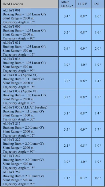
Table 2: Magnitude of Effect of Head Location on Perceived Pitch Angle for Various ALHAT Trajectories
Head Location Altair LDAC-2 LLRV LM ALHAT 001
Braking Burn = 1.05 Lunar G’s Slant Range = 2000 m Trajectory Angle = 15º
3.4 º 0.8 º 1.6 º ALHAT 006
Braking Burn = 1.05 Lunar G’s Slant Range = 2000 m Trajectory Angle = 90º
3.2 º 0.8 º 1.6 º ALHAT 031
Braking Burn = 1.05 Lunar G’s Slant Range = 500 m Trajectory Angle = 15º
3.6 º 0.9 º 2.0 º ALHAT 036
Braking Burn = 1.05 Lunar G’s Slant Range = 500 m Trajectory Angle = 90º
3.9 º 1.0 º 1.9 º ALHAT 037 (Apollo #1)
Braking Burn = 1.1 Lunar G’s Slant Range = 2000 m Trajectory Angle = 15º
3.2 º 0.8 º 1.4 º ALHAT 038 (Apollo #2)
Braking Burn = 1.05 Lunar G’s Slant Range = 2000 m Trajectory Angle = 30º
3.2 º 0.8 º 1.5 º ALHAT 050 (ALHAT baseline)
Braking Burn = 1.1 Lunar G’s Slant Range = 1000 m Trajectory Angle = 30º
3.1 º 0.8 º 1.4 º ALHAT 217
Braking Burn = 2.0 Lunar G’s Slant Range = 2000 m Trajectory Angle = 15º
3.5 º 0.9 º 1.7 º ALHAT 222
Braking Burn = 2.0 Lunar G’s Slant Range = 2000 m Trajectory Angle = 90º
2.1 º 0.5 º 1.0 º ALHAT 247
Braking Burn = 2.0 Lunar G’s Slant Range = 500 m Trajectory Angle = 15º
3.9 º 1.0 º 1.9 º ALHAT 252
Braking Burn = 2.0 Lunar G’s Slant Range = 500 m Trajectory Angle = 90º
1.1 º 0.3 º 0.6 º
As seen in Table 2, the effect of head location on the astronaut’s perceived pitch angle although never exceeding,3.9º, was large enough to be perceived. Looking at the two Apollo-like trajectories (037 and 038) with head location similar to that of the LM, it is seen that the astronauts may have experienced effects on perceived pitch of 1.4-1.5º due to their head locations according to the simulation of the Observer model. These effects are much smaller than those that are expected for the head location in the larger Altair LDAC-2 vehicle. For all the trajectories the tangential acceleration was significantly larger than the centripetal acceleration; thus the angular acceleration is the critical quantity for a given trajectory.
Beyond the automated trajectories defined in the ALHAT tradespace of Figure 3, the effect of head location can be studied for trajectories that include a LP redesignation or direct manual control. The trajectories used for this analysis
0 100 200 300 400 500 600 -100 -50 0 50 pi tc h ang le [ d e g
] Actual and Perceived Pitch Angle with CG Head Location
actual perceived 0 100 200 300 400 500 600 -100 -50 0 50 pi tc h a ngl e [d eg
] Actual and Perceived Pitch Angle with Altair LDAC2 Head Location
actual perceived 0 100 200 300 400 500 600 -4 -2 0 p itc h e rro r [d e g
] Effect of LM vs. CG Head Location on Perceived Pitch Angle
were the two presented in Figure 14 and Figure 15 as well as two additional trajectories. The additional trajectories were another LP redesignation trajectory and another pilot manual control trajectory, but in the forward/pitch direction instead of the left/roll direction. The effect of the head location on perceived orientation was calculated in the same way shown in Figure 16 with the exception that since the maneuvers for redesignation and manual control were in both pitch and roll, the tilt angle was used instead of just the one dimentional pitch angle previously used. Table 3 shows the effect on tilt angle for these two trajectories for each of the head locations defined in Table 1.
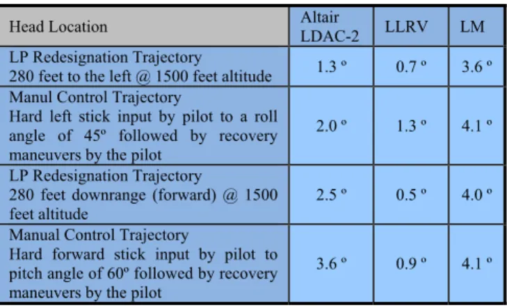
Table 3: Magnitude of Effect of Head Location on Perceived Tilt Angle for Simulated LP Redesignation
and Manual Control Trajectories
Head Location Altair LDAC-2 LLRV LM LP Redesignation Trajectory
280 feet to the left @ 1500 feet altitude 1.3 º 0.7 º 3.6 º Manul Control Trajectory
Hard left stick input by pilot to a roll angle of 45º followed by recovery maneuvers by the pilot
2.0 º 1.3 º 4.1 º LP Redesignation Trajectory
280 feet downrange (forward) @ 1500 feet altitude
2.5 º 0.5 º 4.0 º Manual Control Trajectory
Hard forward stick input by pilot to pitch angle of 60º followed by recovery maneuvers by the pilot
3.6 º 0.9 º 4.1 º
As seen in Table 3, the LP redesignation and manual control trajectories contained manuevers that created comparable effects of the head location on tilt angle to those seen for the automated ALHAT trajectories. Whereas the maximum head location effect for the ALHAT trajectories was always created during the pitch-over maneuver, the maximum effect for the resdignation and manual control trajectories was nearly always created from maneuvers during the approach. Interestingly, the redesignation to the left and the manual control trajectories with the large roll input actually created fairly small effects for the Altair LDAC-2 head location compared to the those previously seen. This is due to the head location assumption for the Altair LDAC-2 design being very far forward from the COM (large rx), but
not very high above the COM (small rz). As a result, the
tangetial accelerations created from the head location offset were fairly small from maneuvers that were primarily about the roll axis. Manuevers that were primarily pitch maneuvers, such as those in the downrange resignation and forward manual control trajectories, resulted in much larger effects for the Altair LDAC-2 head location.
While for the ALHAT trajectories the Altair LDAC-2 head location always had a greater effect than the LM head location, for the redesignation and manual control trajectories this was not the case. The LM head location which was not as far forward, but higher up than the Altair LDAC-2 head location, was seen to have a greater effect for
the trajectories in Table 3. This was due to the redesignation and manual control trajectories in Table 3 having significant angular accelerations in both the roll and pitch directions. The result is greater disorienting tangential accelerations the higher the head location is above the COM. While the LM head location is not as far from the COM as the Altair LDAC-2 head location, it is much higher above the COM. The result is maneuvers which combined roll and pitch can have a large effect for the LM head location. This was seen in Table 3 for redesignation and manual control trajectories that incorporated both pitch and roll maneuvers, often simultaneously.
8. DISCUSSION AND CONCLUSIONS
The automated lunar landing trajectories generated by ALHAT provided motion inputs into Observer, a human orientation estimation model. We show how pitch angle may be significantly misestimated for the majority of the landing trajectory. The descent engine thruster inherently causes the GIF to align with the vehicle “down axis” during the descent. Due to the inherent accelerations - gravity, ambiguity of the otolith organ signals the astronaut will experience a somatogravic illusion. This causes the astronaut’s perception to be upright, when for the majority of the trajectory, he is pitched significantly back, even beginning flat on his back. Similar analysis was done for a trajectory with a simulated LP redesignation to the left of the vehicle and for a trajectory that included pilot manual control inputs commanding a hard roll maneuver. The somatograic illusion was seen to arise for these trajectories as well. Despite the vehicle reaching significant roll angles, the astronaut may experience the illusion of being nearly upright. This illusion has the potential to be very disorienting. The pilot may use his perception of tilt as a proportional measure of vehicle horizontal acceleration, which is essential when trying to null velocities during terminal descent. Misperceptions of vehicle orientation will provoke invalid command inputs by the pilot. These incorrect command inputs will result in less efficient maneuvers and poor performance. Even worse, the consistent underestimation of tilt angle could cause the pilot to command too large of stick inputs which often leads to pilot induced oscillations (PIO). This type of pilot error often results in accidents.
Next, the effect of the astronaut’s head location within the vehicle was analyzed by using the Observer model to analyze a series of trajectories within the ALHAT trade space assuming head locations approximating the Apollo LM, LLRV, and the Altair LDAC-2 design. The effects of the head location were found to be small, but measurable (0.3-3.9 º). The greatest effect of head location was found for the Altair LDAC-2 vehicle design because the head was farthest away from the COM. The implication of this result is that even if pilots have not experienced disorientation on the LM or LLRV, they may still be become disoriented in a vehicle with astronaut head location at the Altair LDAC-2 position. In the design on the Altair vehicle, the effect of
the astronaut’s head location on spatial disorientation should be considered. A lunar landing vehicle that attempts to place the astronaut’s head location too far from the vehicle COM will contribute to errors in the astronaut’s perceived pitch angle and spatial orientation. There was also significant variation between the different ALHAT trajectories, primarily due to different maximum angular acceleration values. Certain trajectories could minimize disoreinting illusions.
Additionally two landing point redesignation trajectories, one forward and one to the left, as well as two manual control trajectories, were studied for the effects of head location. It was seen that comparable maximum effects on the tilt angle were seen for these trajectories as the automated ALHAT trajectories, with the effects ranging from 0.7º to 4.1º. While in the automated trajectories the largest effects were seen for the Altair LDAC-2 head location, the greatest effects were seen for the LM head location with the redesignation and manual control trajectories. These trajectories include combinations of roll and pitch maneuvers, often simultaneously, and are more affected by the high head location of the LM position than by the forward head locaiton of the Altiar LDAC-2 position. A very far forward head location is only more disorienting than a very high head location for pure pitch maneuvers. For most combined roll and pitch maneuvers, as would be present for most LP redesignations and manually controlled approaches and descents, a head location above the COM is far more disorienting than a head location in front of the COM. Therefore for the current Altair LDAC-2 design head location, which is mostly forward of the COM and only slightly above the COM, the pitch-over maneuver might be somewhat disorienting but general redesignations and manual controlled maneuvers should not result in any additional disoriention. A change in the head location to farther above the COM would result in greater disorientation during general redesignations and manually controlled maneuvers.
By determining the types of illusions which might occur, planning can take place to prevent the occurrence. For example, it was seen that the head offset from the vehicle COM creates tangential and centripetal accelerations which can result in perceived tilt motion due to a somatogravic illusion. With this knowledge, designers can work to keep the astronauts from being located too far from the vehicle COM, particularly not too far above the COM. Additionally, countermeasures could be incorporated to prevent spatial disorienation. In particular, training and novel display concepts can be implemented. If the particular type of illusion that is likely to occur at each point during the landing is known, then displays to address these particular illusions can be designed and used in the landing vehicle. This should increase spatial and geographical awareness, which is critical in improving landing performance and safety.
The Observer model is very useful for analyzing spatial disorientation in conditions that are not easy to reproduce. Unfortunately, the application of the model has not been empirically verified sufficiently in low gravity environments or after 0-g adaptation, as the astronauts will experience. The Observer model is only intended to model average perceptions and does not account for intra and inter subject variablity. It only provides an approximation of how the human vestibular organs interpret motion signals.
Additionally, the influence of limited and distorted visual cues during the lunar landing is not well understood and was not included in the Observer model. Thus the results depict only the processing and integration of vestibular signals. In order to incorporate visual cues, visual inputs have been added to the Observer model recently. However, additional validation is needed prior to trusting the model outputs.
ACKNOWLEDGMENTS
We acknowledge Draper Laboratoriy’s ALHAT project for contributing the candidate lunar landing trajectories for analysis and Michael Newman of MIT for his help in modifying and adapting the Observer model, developed with support from NSBRI project SA01302 (R. Small PI), to work with lunar landing trajectories. This work was supported by the National Space Biomedical Research Institute through NASA NCC9-58-11, Project SA01604.
REFERENCES
[1] Hackler, C., J.R. Brickel, et al. (1968) “Lunar Module Pilot Control Considerations (NASA TN D-4131).” Manned Spacecraft Center: Houston, TX.
[2] Cheatham, D.C. and C.T. Hackler. (1964) “Handling Qualities for Pilot Control of Lunar-Lander Spacecraft (NASA-TM-X-57138).” AIAA/NASA Third manned Space Flight Meeting.
[3] Cheatham, D.C. and F.V. Bennett. (1968) “Apollo Lunar Module Landing Strategy.”
[4] Project Technical Requirements Specification for the Autonomous Landing and Hazard Avoidance Technology (ALHAT) System, Revision 0, March 28, 2007.
[5] Epp, C.D. and T.B. Smith (2007) “The Autonomous Precision Landing and Hazard Detection and Avoidance
Technology (ALHAT).” In IEEE Aerospace Conference.
[6] Paschall, S.C., T. Brady, et al. (2008) “A Self Contained Method of Safe and Precise Lunar Landing.” In IEEE Aerospace Conference.
[7] Gillingham, K.K. and F.H. Previc. (1996). “Spatial orientation in flight.” Fundamentals of Aerospace Medicine. RL DeHart. Baltimore, MD, Williams and Wilkins: 309-397.
[8] Newman, M.C. (2009) “A Multisensory Observer Model for Human Spatial Orientation Perception.” [9] Oman, C.M (1991). “Sensory Conflict in Motion
Sickness: an Observer Theory Approach in Pictorial communciation in real and virtual environments.” S. Ellis, Editor, Taylor and Francis: London. P. 362-267. [10] Young, L.R. and C.M. Oman (1969) “Model for
vestibular adaptation to horizontal rotation.” Aerospace Medicine 40(10):p. 1076-80.
[11] Borah, J., L. Young, and R. E. Curry. (1979) “Optimal estimator model for human spatial orientation.” IEEE Trans. Systems, Man and Cybernetics p. 800-805. [12] Raphan, T., V. Matsuo, and B. Cohen (1979) “Velocity
storage in the vestibulo-ocular reflex arc (VOR)”. Experimental Brain Research, 35:p. 229-248.
[13] Robinson, D.A. (1981) “The use of control systems analysis in the neurophysiology of eye movements.” Annual Review of Neuroscience, 4:p. 463-503.
[14] Merfeld, D.M., L.R. Young, C.M. Oman, and M.J. Shelhammer, (1993) “A multidimensional model of the effect of gravity on the spatial orientation of the monkey.” J Vestib Res, 3(2):p. 141-61.
[15] Merfeld, D.M. (2003) “Rotation otolith tilt-translation reinterpretation (ROTTR) hypothesis: A new hypothesis to explain neurovestibular spaceflight adaptation.” J Vestib Res. 13:p. 309-320.
[16] Merfeld, D.M. and L.H. Zupan, (2002) “Neural processing of gravitoinertial cues in humans. Ill. Modeling tilt and translation responses.” J. Neurophysiol. 87(2):p.819-833.
[17] Vingerhoets, R.A.A, Van Ginsbergen, J.A.M., Medendorp, W.P., (2007) “Verticality perception during off vertical axis rotation.” J. Neurophysiol. 97:3256-3268.
[18] Oman, C.M. and M.C. Newman (2009) “Observer model for spatial orientation research and accident investigation (abstract).” Aviation Space and Environmental Medicine 80(3):208.
[19] Forest, L.M., B.E. Cohanim, et al. (2008) “Human Interactive landing Point Redesignation for Lunar Landing.” IEEE Aerospace Conference.
[20] Epp, C.D., E.A. Robertson, T. Brady (2008) “Autonomous Landing and Hazard Avoidance Technology (ALHAT).” IEEE Aerospace Conference. [21] Johnson, M.C. (2008) “A Parameterized Approach to
the Design of Lunar Lander Attitude Controllers” in AIAA Guidance, Navigation, and Control Conference. [22] Sostaric, R. and S. Paschall. (2007) “ALHAT GNC
Analysis and Trajectories,” Lunar Landing Program Office ALHAT Review.
BIOGRAPHY
Torin K. Clark is a graduate student
in the Man Vehicle Laboratory at the Massachusetts Institute of Technology. He is currently working on a project analyzing the potential of spatial disorientation during lunar landing and designing novel displays as a countermeasure. He holds a B.S. in Aerospace Engineering and a Minor in Applied Mathematics from the University of Colorado at Boulder and is a SM.. Candidate in the Department of Aeronautics and Astronautics at MIT.
Alexander J. Stimpson is a
graduate student in the Man Vehicle Laboratory at the Massachusetts Institute of Technology. He is currently working on a project analyzing the potential of spatial disorientation during lunar landing and designing novel displays as a countermeasure. He holds a B.S. in Bioengineering from the University of Florida and is a SM. Candidate in the Department of Aeronautics and Astronautics at MIT.
Kevin R. Duda is Senior Member of
the Technical Staff in the Human-Systems Collaboration Group at the Charles Stark Draper Laboratory. He has worked a variety of programs related to the design and analysis of spacecraft automation, decision support systems, and mission planning. He currently is the PI on a project modeling and analyzing lunar lander supervisory control performance, and is a co-I on a project designing and analyzing lunar lander manual control performance; both projects are funded by the National Space Biomedical Research Institute. He is an instrument rated private pilot and holds a B.S. in Aerospace Engineering from Embry-Riddle Aeronautical University and a M.S. and Ph.D. in Aeronautics and Astronautics from MIT.
Charles M. Oman is a Senior
Lecturer and Senior Research Engineer in the Department of Aeronautics and Astronautics and the Director of the Man Vehicle Laboratory at MIT. His research addresses the physiological and cognitive limitations of humans in aircraft and spacecraft. He has flown numerous experiments on Shuttle/Spacelab. He currently leads the Sensorimotor Adaptation Research Team of the National Space Biomedical Research Institute, is PI on two NSBRI projects, and a co-I on two others. He holds a B.S. in Aerospace & Mechanical Sciences from Princeton University and an MS and Ph.D. in Aeronautics and Astronautics from MIT.
Laurence R. Young is Apollo
Program Professor of Astronautics and Professor of Health Science and Technology at MIT. He was the founding Director of the National Space Biomedical Research Institute and directs the HST Ph.D. program in Bioastronautics. He has worked on many different projects related to manned spaceflight and is currently a PI on a project designing and analyzing lunar lander manual control performance and is a co-I on a project modeling and analyzing lunar lander supervisory control performance. He holds an A.B. in Physics from Amherst College, S.B. in Electrical Engineering from MIT, S.M in Electrical Engineering and Sc.D. in Instrumentation from MIT.
![Figure 2: Lunar Landing Phases [22]](https://thumb-eu.123doks.com/thumbv2/123doknet/13971998.453752/3.918.96.425.399.724/figure-lunar-landing-phases.webp)
![Figure 3: ALHAT Trajectory Trade Space [6]](https://thumb-eu.123doks.com/thumbv2/123doknet/13971998.453752/4.918.485.832.222.490/figure-alhat-trajectory-trade-space.webp)