AirShare: Distributed coherent transmission made seamless
The MIT Faculty has made this article openly available. Please share
how this access benefits you. Your story matters.
Citation
Abari, Omid, Hariharan Rahul, Dina Katabi, and Mondira Pant.
“AirShare: Distributed Coherent Transmission Made Seamless.”
2015 IEEE Conference on Computer Communications (INFOCOM)
(April 2015), Kowloon, Hong Kong, 2015.
As Published
http://dx.doi.org/10.1109/INFOCOM.2015.7218555
Publisher
Institute of Electrical and Electronics Engineers (IEEE)
Version
Author's final manuscript
Citable link
http://hdl.handle.net/1721.1/114995
Terms of Use
Creative Commons Attribution-Noncommercial-Share Alike
AirShare: Distributed Coherent Transmission Made Seamless
Omid Abari, Hariharan Rahul, and Dina Katabi
Mondira Pant
Massachusetts Institute of Technology
Intel Corporation
{abari, rahul, dina}@csail.mit.edu
[email protected]
Abstract– Distributed coherent transmission is necessary for
a variety of high-gain communication protocols such as dis-tributed MIMO and creating codes over the air. Unfortunately, however, distributed coherent transmission is intrinsically diffi-cult because different nodes are driven by independent clocks, which do not have the exact same frequency. This causes the nodes to have frequency offsets relative to each other, and hence their transmissions fail to combine coherently over the air.
This paper presents AirShare, a primitive that makes dis-tributed coherent transmission seamless. AirShare transmits a shared clock on the air and feeds it to the wireless nodes as a reference clock, hence eliminating the root cause for incoherent transmissions. The paper addresses the challenges in designing and delivering such a shared clock. It also implements AirShare in a network of USRP software radios, and demonstrates that it achieves tight phase coherence. Further, to illustrate AirShare’s versatility, the paper uses it to deliver a coherent-radio abstrac-tion on top of which it demonstrates two cooperative protocols: distributed MIMO, and distributed rate adaptation.
1
I
NTRODUCTIONDistributed cooperative PHY protocols are theoretically well understood to provide large gains in throughput and reliability in a large variety of scenarios. These include distributed MIMO [1], [2], [3], distributed modulation [4], distributed compressive sensing over the air [5], [6], distributed lattice coding [7], noisy network coding [8], and transmitter cooper-ation for cognitive networks [9]. These schemes assume that independent wireless nodes can perform distributed coherent transmission–that is, they can transmit their signals without phase drifts with respect to each other.
However, practical radios do not provide distributed coherent transmission. Independent wireless nodes have different crystal oscillators generating clocks with different frequencies. As a result, different nodes always have an offset in their carrier frequencies (CFO); the CFO causes signals transmitted by every pair of nodes to rotate with respect to each other, and their phases to drift over time. Thus, even if two signals start with their phases aligned in a desired manner, the CFO very quickly causes the phases to rotate with respect to each other and the signals to combine in an undesired manner. Typical CFOs between two wireless radios even those that belong to the same technology (e.g., two Wi-Fi radios) and the same manufacturer vary between 100s of hertz to tens of kilohertz [10], [11]. Such CFOs are large enough to lose coherence even within a single packet.1
1. For example, a CFO of a few hundred hertz causes a phase misalignment of π or more in less than one millisecond, leading to highly incoherent signals.
In this paper, we investigate how practical radios may deliver an abstraction of distributed coherent transmission. Designers of cooperative PHY protocols (distributed MIMO, distributed modulation, etc.) would then leverage this abstraction and free themselves from having to work out the details of coherent transmission. The most straightforward approach for delivering such an abstraction would connect the nodes to a shared clock using wires [12]. Such a system eliminates CFO and ensures coherent transmission. However, it defeats the notion of a wireless network and is not practical for mobile nodes. Alternatively, one may connect each node to a GPS clock. Such clocks use the GPS signal and temperature-controlled crystals to maintain a very low CFO with respect to each other. Unfor-tunately, however, GPS clocks are power-hungry, cost hundreds to thousands of dollars, and do not work in indoor settings [13], [14]. As a result, they are neither suitable for sensor nodes nor indoor Wi-Fi deployments. In the absence of a suitable generic abstraction for distributed coherence, most wireless cooperation protocols have remained theoretical [7], [8], [9], [6]. The few protocols which were demonstrated empirically address the coherence issue within a particular context. For example, systems like [15], [10] implement distributed MIMO, but focus specifically on OFDM systems in their phase tracking and compensation algorithms. In contrast, solutions like [16] focus on the RFID technology, where nodes are passive reflectors that do not have CFO. Neither of these solutions however provide a generic coherence abstraction that can be leveraged by various cooperative PHY protocols, and applied broadly across technologies (Wi-Fi, ZigBee, Bluetooth).
Ideally, one would like a solution that: (a) avoids wires and supports mobility. (b) Further, it should be independent of the protocol and the radio technology so that it might be used by a variety of technologies (e.g., Wi-Fi, ZigBee, Bluetooth) to build existing or future distributed communication protocols (e.g., distributed MIMO, distributed compressive sensing, or other cooperative PHY protocols.) (c) Finally, it should be cheap and low-power so that it may be incorporated with cheap wireless nodes such as sensors.
This paper presents AirShare, a primitive that makes dis-tributed coherent transmission seamless while satisfying the above three requirements. At a high-level, AirShare transmits a shared clock on the air and feeds it to the wireless nodes as a reference clock, hence eliminating the root cause for incoher-ent transmissions. Networks interested in using AirShare for coherent transmission deploy a AirShare clock emitter within radio range, and add a simple circuit to each node to capture the shared clock.
Transforming this design into a practical system, however, requires overcoming multiple challenges.
• Perhaps the most fundamental challenge is: How do we transmit the shared reference clock? At first blush, it might
seem that we could just transmit the reference clock signal over the air. The problem, however, is that wireless nodes typically use for their reference clock a sine wave of 10 MHz to 40MHz [17]. FCC regulations, however, forbid transmit-ting such a low-frequency signal for unlicensed use [18]. Besides, receiving a signal efficiently at this low frequency requires antennas that are several meters long [19], which is impractical for typical wireless nodes. In §2.2, we explain how AirShare addresses this problem by introducing a new approach that extracts a low-frequency clock from multiple high-frequency sine waves.
• Second, the circuit used by the individual nodes to receive the clock has to be simple and low-power. It also should be possible to integrate this circuit with existing radio designs as an add-on module, independent from the details of the radio technology (whether it is ZigBee, Wi-Fi, etc.). In §2.3, we describe the detailed design of AirShare, demonstrating that the per node circuit includes only simple analog components such as a mixer and a filter and does not need any digital receive chain, allowing it to stay cheap and low-power. Further, it operates as an add-on module that is oblivious to the details of the radio.
• Finally, in §2.4, we describe how AirShare deals with various impediments that affect the wireless medium, including the possibility of the clock fading at some of the nodes. We built a prototype of AirShare and integrated it with USRP software radio to show that it can be used to augment off-the-shelf radios. We evaluated AirShare and its applications in a wireless testbed with line-of-sight and non line-of-sight scenarios. Our results reveal that AirShare provides tight phase synchronization across multiple nodes. In particular, in our testbed, the median and 95th percentile CFO between two
AirShare nodes operating at 2.45 GHz are 0.38Hz (0.16 parts per billion) and 1.24Hz (0.5 parts per billion) respectively. AirShare can thus achieve orders of magnitude tighter synchro-nization than the traditional situation of free running oscillators on independent nodes.
To demonstrate AirShare’s versatility we used it as a coher-ence abstraction to build two cooperative protocols:
• Distributed MIMO Distributed MIMO is a powerful con-cept that allows multiple wireless transmitters to behave like one huge MIMO transmitter with the number of antennas equal to the sum of antennas on all the cooperating nodes. To evaluate how AirShare enables distributed MIMO, we took 10 USRPs that implement Wi-Fi OFDM physical layer. We divided the nodes to 5 transmitters and 5 receivers, and equipped the transmitters with the AirShare clock recipient circuit. We then made the transmitters transmit concurrently to the 5 receivers, while applying MIMO multiplexing. Our results show that AirShare delivers a distributed MIMO system whose throughput scales linearly with the number of transmitters. Specifically, with 5 transmitters, AirShare’s distributed MIMO delivers a median throughput gain of 4.4× over traditional 802.11 style unicast.
• Distributed Rate Adaptation Traditional sensor systems such as ZigBee [20] are typically limited to a single low-density modulation, (e.g., BPSK). As a result, they can-not exploit good channel conditions to transmit at dense modulation (e.g., 16-QAM) and achieve higher spectral efficiency. A recent work has proposed a distributed scheme
that enables nodes to transmit concurrently and combine their signals over the air, creating a rate-less modulation scheme that adapts the bits per transmitted symbol to the channel quality [16]. Since this design requires coherent transmission, it has been limited to only RFID nodes which do not have local oscillators or CFO with respect to each other.
We show that AirShare extends such distributed modulation and rate adaptation to generic sensors. We have used our AirShare-equipped USRPs to emulate ZigBee sensors and perform distributed modulation and rate adaptation as de-scribed in [16]. Our results show that an AirShare-based ZigBee system can adapt modulation and bitrate to channel quality and achieve throughput gains over traditional ZigBee. Specifically, with 6 ZigBee nodes transmitting jointly to a central node, AirShare provides throughput gains of 1.6−3× across a range of SNRs (5-25 dB).
We believe that AirShare provides an important step toward enabling distributed cooperative PHY protocols at the physical layer, and adds a useful primitive to the toolkit available for building such protocols.
2
A
IRS
HAREAirShare enables independent wireless nodes to transmit coherently by sharing a reference clock transmitted over the wireless medium. In this section, we explain how AirShare works. We start with a description of how radios use a reference clock for transmission and reception, and why the existing system leads to incoherent transmissions. We then describe the structure of AirShare’s shared reference signal. We follow with the circuit details and how AirShare can be incorporated in a wireless node as an add-on module.
2.1 Why Do Wireless Nodes Have CFO?
Wireless signals are transmitted at a particular carrier fre-quency. The signal is up-converted from baseband to the carrier RF frequency at the transmitter and down-converted back to the baseband at the receiver. Both up-conversion and down-conversion are performed by a process called mixing, where the signal is multiplied by the carrier frequency. Thus, both transmitter and receiver need to generate the RF carrier signal with a precise and stable frequency.
Each node generates the carrier frequency as follows: The node has a local crystal that produces a low frequency sine wave, which is used as a reference clock. This reference clock is fed to a special circuit called a Phase Locked Loop (PLL), which uses it to generate the desired carrier frequency. For example, if the node is a Wi-Fi radio, the crystal might generate a 10 MHz sine wave, which the PLL then upconverts to a center frequency in the 2.4 GHz bands.
The key problem is that reference clocks on different nodes have slight differences in their frequencies, because different crystals naturally have different properties. Since the PLLs on different nodes lock to reference clocks with different frequencies, their output signals have different frequencies, and this leads to frequency offsets (CFO) between nodes.
It is important to realize that the CFO is not a constant value. Even minute variations of 0.1 degree in the temperature can cause CFO variations of a few hundred hertz [21], [22].
2f2
f2-f1
DC 2f1 f1+f2
f1 f2 f1 f2
Fig. 1—Illustration of AirShare’s Design. Wireless nodes multiply the
received signal by itself and extract the desired clock signal by applying a band pass filter centered at fref.
Similarly, noise in the supply voltage cause fast variations in the crystals frequency [22].
2.2 How Does AirShare Work?
AirShare eliminates the root cause for incoherent transmis-sion by ensuring that all nodes feed their PLL with the same reference clock that they receive over the wireless medium. Due to FCC regulations, however, one cannot simply transmit a 10MHz clock signal on the wireless medium. Also, one cannot simply up-convert the clock at the transmitter and down-convert it at the receiver, since this introduces a chicken-and-egg problem. Upconversion and downconversion to a band will require independent carrier generation at the transmitter and receiver. Since the reference signals for these independent carriers are generated by different crystals, they will have frequency offset relative to each other, leading to a frequency offset in the downconverted reference signal at different nodes.2 To address this problem, AirShare transmits a signal with a specific format such that it can be used to extract a reference clock without any other additional information. Specifically, AirShare transmits two single frequency tones (i.e., sine or cosine waves) separated by the desired clock frequency. These tones might be transmitted in the newly opened white spaces, e.g., for a clock of 10 MHz, AirShare can send tones at 175 MHz and 185 MHz. Let us denote the transmitted tones by f1 and f2, and the desired clock frequency by fref = f2− f1,
then the transmitted signal can be written as:
Stx(t) = A1cos(2π · f1· t) + A2cos(2π · f2· t). (1)
This signal passes over the wireless channel before reception, and the received wireless signal can be written as:
Srx(t) = B1· cos(2π · f1· t + φ1) + B2· cos(2π · f2· t + φ2), (2)
where B1, B2, φ1 and φ2 capture the channel impact.
To obtain the shared clock, each wireless node multiplies the received signal by itself and applies a band pass filter to extract the desired clock frequency. To see why this works, recall that the multiplication of two tones at different frequencies produces tones whose frequencies are the sum and difference of the original frequencies. Hence, after multiplying the received signal with itself the node obtains:
Sm(t) = [B1· cos(2π · f1· t + φ1) + B2· cos(2π · f2· t + φ2)]2
2. Note also that one cannot simply transmit a high frequency signal and generate the desired clock frequency from it using a PLL configured as a divider. This is because the high frequency PLL input will need to be passed through a very narrow (high-Q) band pass filter to reject any surrounding noise, and such filters are not practical at high frequencies.
Emitter
Recipient Wireless
Node
Fig. 2—AirShare’s Network Topology. An AirShare emitter transmits the
reference signal. Wireless nodes that are equipped with AirShare recipient components receive the AirShare signal and extract the reference clock.
Simplifying this equation results in:
Sm(t) = B1B2cos(2π · (f2− f1) · t + (φ2− φ1)) + B1B2cos(2π · (f2+ f1) · t + (φ2+ φ1)) +B 2 1 2 + B21 2 · cos(2π · 2f1· t + 2φ1) +B 2 2 2 + B22 2 · cos(2π · 2f2· t + 2φ2) (3)
This signal includes a DC component, some high frequency components at 2f1, 2f2 and f1+ f2, and a component at f2− f1 (highlighted in bold in the formula above) which is equal
to the desired reference frequency fref. Hence, a simple
band-pass filter centered at the reference clock frequency fref (e.g.,
10 MHz) is used to extract the single-tone reference signal, as illustrated in Fig. 1.
The signal after the filter will be:
Sref(t) = B1B2cos(2π · (f2− f1) · t + (φ2− φ1))
= B1B2cos(2π · fref · t + δφ).
(4) This signal is then used as an input to the node’s PLL. Since all nodes feeds their PLL with a reference clock of the exact same frequency, they will have no CFO with respect to each other. Further, even if the frequency of the clock signal varies due to variation in the temperature or supply voltage at the clock transmitter, all nodes will see the same frequency variation in their reference clocks and hence stay coherent.
2.3 AirShare’s System Architecture
Architecturally, AirShare has two components: a clock emit-ter and a clock recipient. To enable a set of nodes to transmit coherently, one deploys a AirShare clock emitter in the network and equip each node with a AirShare clock recipient as illustrated in Fig. 2.
Emitter: Fig. 3(a) presents the AirShare emitter circuit. To
transmit the AirShare signal, we start with a local oscillator (i.e., a crystal) that generates a reference signal, and feed its output to two PLLs to generate two tones, f1 and f2, that are
separated by the desired clock frequency fref. The two tones
are then amplified using a power amplifier and transmitted on the wireless medium. Note that our signal does not occupy the entire band between f1and f2, it simply consists of two
single-tones which are separated by the desired clock frequency.
Recipient: Fig. 3(b) presents the AirShare recipient circuit. The
AirShare recipient receives the emitted signal. As is usual in RF radios, the received signal is passed to a low-noise amplifier (LNA) and the band of interest (from f1 to f2) is filtered out
Reference Combiner PA f1 f2 PLL f1 PLL f2
(a) AirShare Emitter
(b) AirShare Recipient
Fig. 3— AirShare’s System Architecture. The AirShare emitter includes two
PLLs to generate two single tones separated by the desired frequency. The AirShare recipient mixes the received AirShare signal with itself and extracts the reference clock using a band pass filter.
using a band pass filter. After filtering, the signal is mixed with itself and the desired reference clock is extracted using a band pass filter centered at the reference frequency (e.g., 10 MHz), and input to a PLL whose output is fed to the wireless node.
Finally, we note a few points:
• First, AirShare is protocol and technology independent, and the AirShare recipient circuit can be incorporated in various radios (Wi-Fi, ZigBee, etc.) as an external clock that feeds the PLL.
• Second, the AirShare recipient circuit is simple and cheap and hence can be incorporated in low-end wireless nodes. In particular, the circuit does not need any analog to digital converters (ADC) or baseband processing. It is composed of cheap and off-the-shelf components such as amplifiers, band pass filters, a splitter, and a mixer. Further, the splitter, mixer and filters are all passive components and do not need power supply. Most of the power consumption is due to the LNA. An LNA that operates in the white space frequency range consumes only 7-10 mW [23], which is less than 0.1% of the power consumption of a Wi-Fi AP [24], and about 10% of the power consumption of a Zigbee node [25].
• Third, while AirShare transmits two tones separated by 10 MHz, these tones are single frequencies and hence occupy very little bandwidth. Others can transmit in the spectrum between the tones as long as they leave a buffer of about 1 MHz around each tone. The band pass filter around fref in
the recipient circuit can extract the desired reference clock without interference.
2.4 Dealing with Wireless Channel Impediments
Fading: Similar to other wireless systems, AirShare tones can
suffer from multipath fading. In particular, either of the tones used by AirShare can be faded at wireless nodes using AirShare recipients. In such a case, the wireless node will not be able to participate in coherent transmission. Let p be the probability that any single tone is faded at one of the nodes participating in coherent transmission. Since the two tones are separated by a wide gap of 10 MHz, we can treat the fading at the two tones as independent. The probability of node failure, i.e., the probability that either tone is faded, is therefore:
P(fail) = 2p(1 − p) + p2= 2p − p2
For example, in a case where fading happens with 1% proba-bility, the node will fail with a probability of 2%. This may not be tolerable for some applications. To reduce the failure rate, our solution is to transmit three tones instead of two tones. For example, the AirShare emitter can transmit tones at 175 MHz, 185 MHz and 195 MHz. In this case, the recipient can pick any combination of two tones. In particular, it can pick the two strongest tones it receives.3 Note that since these three tones
are generated from the same reference crystal at the emitter, clocks generated using any combination of two tones will not have CFO with respect to each other. In this case, a node fails when two tones or all three tones are faded at that node. This happens with probability
P(fail) = 3p2(1 − p) + p3= 3p2− 2p3
(5) As can be seen from the equation, the failure rate is reduced quadratically with the addition of a single tone. For the same example as before, where the fading probability is 1%, the failure rate is reduced to 0.03%. Note that this failure rate is much lower than the typical packet loss in Wi-Fi networks.
Multipath: AirShare continues to work in non-line-of-sight
multipath scenarios. In this case, an AirShare recipient receives multiple delayed versions of the signal, each of which encoun-ters a different channel. Note that adding multiple copies of signals at f1and f2, each with a different attenuation and phase,
does not change the output frequency of AirShare. Specifically, similar to Eq. 4, the AirShare recipient still produces an output reference clock with frequency fref. We demonstrate
empirically in§4.1 that AirShare’s performs well in non-line-of-sight multipath-rich scenarios.
Interference: AirShare can be affected by interference, just
like other unlicensed band systems. This causes the PLL in the affected node to lose its lock to the reference. In this case, the lock detect circuitry (a standard feature in PLLs) signals the node to fall back to the on-board clock. This allows the node to operate correctly until the transient interference clears. A node suffering from interference however cannot take part in coherent transmissions and has to transmit separately as in today’s systems. Other nodes in the network can continue to participate in coherent transmission using AirShare.
2.5 Range of AirShare Emitter
The signal transmitted by the AirShare emitter propagates through the medium, is amplified by the receive chain at the AirShare recipient, and is then input to the PLL. We can write the received power at the input of the PLL as:
PLL Input Power= Emitter Transmitted Power − Path Loss + Recipient Rx Chain Gain (6) Given a particular AirShare implementation, we can deter-mine the emitter transmitted power and the recipient Rx chain
gainand substitute them in the above equation. We can then work back: measure the minimum required PLL input power so that it can lock on the signal, and estimate the maximum tolerable path loss using Eq. 6. Then, based on standard 3. The PLLs can use either 10MHz or 20MHz as their reference. They simply need to be configured to use a different multiplier ratio, a typical feature available in PLLs.
channel models, we can translate this maximum tolerable path loss to the maximum propagation distance for AirShare.
Based on the above, the values in Eq. 6 can be computed as:
PLL Input Power: Based on our empirical measurements, the
signal at the input of the PLL must be at least -17 dBm to enable the PLL to lock.
Recipient Rx Chain Gain: The total gain of the recipient
receiver chain (antenna, amplifiers, mixer and filters) is 15 dB.
Emitter Transmitted Power: The signal strength from the
emitter is determined by FCC regulations. For the whitespaces, the FCC limits the total transmitted power including the transmitted antenna gain to 18.6 dBm in any 100kHz band.4
Since AirShare uses two different tones separated by 10 MHz, it can use double this transmitted power for a total transmitted power of 21.6 dBm.
Path Loss: Substituting these numbers in Eq. 6, we can
compute the maximum tolerable path loss as 53.6 dBm. In order to translate this into a distance, we use the standard link budget/path loss (PL) model [27]:
PL at distance d= PL at reference dist. d0+ 10n log10 d d0
(7) where n is the path loss exponent, and PL is measured in dBm. We use the standard Friis equation to determine the path loss at reference distance d0 = 1m. For a frequency of 175 MHz
(wavelength of 1.72m), the path loss at reference distance d0
can be computed as 20log10(1.724π ) = 17.3 dB. Substituting these
in Eq. 7, the maximum allowable distance is 65 m (≈ 210 ft) in a line-of-sight system (n= 2), and 21 m (≈ 70 ft) in a non-line of sight system spread across a large floor (n= 2.76) [27]. This means that a single AirShare emitter can span all nodes in a 210 ft radius circle around it in a line-of-sight scenario, and 70 ft radius around it in a non-line-of-sight scenario.
2.6 Scalability
The previous section evaluated the radius of a deployment across which a single AirShare emitter can synchronize all nodes. We now explain how we can synchronize nodes de-ployed over a region larger than the radius of coverage of a single emitter. Naively, one might think that we can use multiple emitters in different locations to guarantee that each wireless node receives the AirShare signal. However, this solution does not work because each AirShare emitter has a different reference oscillator (i.e., crystal) that it uses to generate its AirShare signal. As a result, signals from different AirShare emitters will have CFO with respect to each other.
Instead AirShare uses a hierarchy of clock emitters. To understand how our proposed solution works, consider the scenario in Fig. 4. Here, we want to eliminate CFO between any pair of four wireless nodes, where nodes 3 and 4 are far from nodes 1 and 2. The master emitter generates the AirShare signal from a local oscillator. Nodes 1 and 2 are in the range of this emitter and use the signal transmitted from the master emitter to generate their reference clocks. However, nodes 3 and 4 are not in the range of the master, and cannot directly receive the 4. The FCC limits conducted power to 12.6 dBm, and allows antenna gain up to 6 dBi [26] Master Emitter 3 1 2 4 Slave Emitter
Fig. 4—AirShare’s is scalable to large networks. In a scenario where nodes
are far from the master AirShare emitter, AirShare uses a slave emitter to regenerate the clock signal. Nodes can synchronize to either the master or slave emitter, and still achieve tight synchronization with each other. AirShare signal. Hence, we use another emitter called a slave
emitter to transmit the AirShare signal to them.
The architecture of a slave emitter is similar to that of the master. However, there is one key difference. A slave emitter does not use a local oscillator as its reference. Instead, it uses an AirShare recipient which listens to the master’s signal to generate its reference. The slave then produces its two tones using this recipient generated reference. In order to avoid interference between master and slave, the frequencies of the AirShare signal generated by the slave need to be different from the frequencies generated by the master. For instance, the slave emitter can use tones at 620 MHz and 630 MHz, while the master emitter uses tones at 175 MHz and 185 MHz.
Note that tones generated by the slave emitter have no CFO with respect to the master emitter because the reference clock for the slave is generated by using the master emitter signal. Consequently, the reference clock extracted from the master emitter signal by wireless node 1 will be synchronized with the reference clock extracted from the slave emitter signal by wireless node 3. Cooperating wireless nodes can pick either the master or the slave signal to extract the shared clock, depending on which of the two are in their radio range. Further, one may cascade multiple master-slave emitters where each slave acts as a master for the next emitter in the cascade. In §4.1, we empirically show that this mater-slave design works in practice.
3
A
IRS
HAREI
MPLEMENTATIONWe built a prototype of the AirShare emitters and recipients as described in §2.3 using off-the-shelf components. For the emitter, we used the following components: Fury Jackson GPSDO as a local oscillator, Analog Devices ADF4350 as PLLs, Mini-Circuits TVA-R5-13 as a power amplifier, Laird Technologies EXB-164-BN as an antenna. For the recipient, we used: Laird Technologies EXB-164-BN as an antenna, Mini-Circuits ZLW-1 as a mixer, Mini-Circuits SBP-10.7+ as bandpass filter around 10MHz, Mini Circuits SHP-175+ as a highpass filter and Mini-Circuits SLP-200+ as a lowpass filter to create a bandpass filter around 175-185 MHz.
We integrate the recipient subsystem with USRP by connect-ing the output of the recipient to the 10 MHz external clock input of the USRP N210 device.
4
E
MPIRICALE
VALUATION OFA
IRS
HAREWe evaluate AirShare in an indoor testbed with line-of-sight and non-line-of-sight scenarios. The testbed spans 10m×10m. All experiments in this section are run with USRP nodes that use OFDM, a 1500 byte packet length, and 10MHz bandwidth.
100 300 500 700 900 0 0.2 0.4 0.6 0.8 1 CFO(Hz) C D F 900 MHz 2.4 GHz
(a) Local Crystal
0 0.5 1 1.5 2 2.5 0 0.2 0.4 0.6 0.8 1 CFO(Hz) C D F 900 MHz 2.4 GHz
(b) AirShare (Note the difference in the scale of the x-axis)
Fig. 5—CFO between pairs of nodes at carrier frequencies of 2.4 GHz and 900 MHz: (a) Independent clocks and (b) AirShare. Comparing (a)
and (b), AirShare reduces the CFO by multiple orders of magnitude.
0 0.5 1 1.5 2 2.5 0 0.2 0.4 0.6 0.8 1 CFO(Hz) C D F 2.4 GHz (non-line-of-sight) 2.4 GHz (line-of-sight) 2.4 GHz (master-slave)
Fig. 6—CFO between pairs of AirShare-equipped nodes at 2.4 GHz carrier frequency. Figure shows that AirShare ensures tight synchronization
of oscillators both in line-of-sight and non-line-of-sight scenarios, as well as in scenarios with master-slave emitters.
The experiments use a total of 6 USRPs. For each evaluation, we run 500 experiments for a variety of the nodes locations.
4.1 Eliminating CFO between nodes
A key promise of AirShare is that it can address the CFO problem. We verify if AirShare delivers on this promise.
Line-of-Sight Experiments. We place an AirShare emitter
in one location in the testbed. We place two USRP nodes equipped with AirShare recipients at two random locations in the testbed, with one acting as a transmitter and the other as a receiver. The transmitter transmits packets consisting of OFDM symbols. The receiver receives these packets, and computes its CFO with respect to the transmitter using the traditional correlation-based OFDM CFO estimation algorithm [28]. We repeat the experiment for two carrier frequencies: 2.4 GHz and 900 MHz, and for a variety of USRP nodes and transmitter receiver locations. We repeat each run both with the USRPs operating using their internal crystals and with the USRPs using the AirShare signal as a reference.
Fig. 5 plots the CDF of the observed CFO for both 2.4 GHz and 900 MHz carriers. The graph in Fig. 5(a) correspond to using the internal crystals, whereas the graph in Fig. 5(b) corre-sponds to using AirShare. The CFO at 900MHz is smaller than
at 2.4 GHz because the PLL multiplies the 10 MHz reference clock by an appropriate factor to deliver the carrier frequency (90 and 240 for 900 MHz and 2.4 GHz, respectively).
The figure shows that when the USRPs operate with their internal crystals, their CFO varies in the range 310Hz–880Hz for a 2.4GHz carrier and 160Hz–370Hz for a 900MHz carrier. The figure also shows that AirShare reduces the CFO by two to three orders of magnitude. Specifically, with AirShare, the median and 95th percentile CFO at 2.4 GHz are 0.4 Hz and
1.24 Hz respectively, and the median and 95th percentile CFO
at 900 MHz are 0.11 Hz and 0.34 Hz, respectively.
To put these numbers in context, consider the accumulated phase error with and without AirShare for a single 1500B packet at the lowest OFDM rate (BPSK, 1/2 rate) used by Wi-Fi. This packet takes≈ 2ms. Thus, with AirShare the median and 95th percentile phase error across this packet are 0.005 radians, and 0.016 radians, which are negligible and have no effect on coherence. In contrast, in the absence of AirShare, the phase errors across the packet would be between 3.9 to 11.1 radians (i.e., over a 180◦change in phase across a packet), and
hence the signals are very far from being combined coherently within the packet [15].
(b) Non-Line of Sight Experiments: We repeat the above
experiment but this time we place the AirShare emitter in a different room such that it has no line of sight to the other nodes in the testbed. Fig. 6 shows the CDF of the measured CFO in the presence of non-line-of-sight channels for a carrier frequency of 2.4 GHz. The median and 95th percentile CFO
in this case are 0.4 Hz and 1.3 Hz respectively, showing that AirShare achieves the same tight performance as in the case of line-of-sight channels.
(c) Impact of using a master-slave deployment: In §2.6, we described how AirShare can scale to large deployments by using a master-slave emitter design. Here, we evaluate the impact of such design on AirShare’s performance.
We place an AirShare master emitter and an AirShare slave emitter within radio range of each other. As before, we con-figure two USRP nodes equipped with AirShare recipients as a transmitter and receiver, respectively. The AirShare recipient on the transmitter receives its clock signal from the master emitter, and the AirShare recipient on the receiver receives its synchronization signal from the slave emitter. As before, we compute the CFO between the transmitter and the receiver.
Fig. 6 plots the CDF of the observed CFO (the dashed line). It shows that the increase in CFO compared to a scenario with only one AirShare emitter is less than 0.1 Hz. Thus, cascading AirShare emitters using a master-slave approach maintains the same orders of magnitude reduction in CFO in comparison to local clocks. The figure also indicates that the system can operate with a longer cascaded chain of master-slave emitters. This is because each emitter in the chain acts as a master for the next emitter. Hence, the worst-case increase in CFO is bounded by 0.1 Hz multiplied by the length of the cascaded chain, which stays small for a chain with a few hops.
4.2 Enabling Coherent Transmission
We examine whether AirShare can enable independent nodes to transmit coherently. We place an AirShare emitter and four USRP nodes at random locations in our testbed. One of the USRPs acts as a receiver and the other three as transmitters.
-0.2 0.2 -0.2 0.2 I Q -0.2 0.2 -0.2 0.2 I Q [1,1,1] [0,0,0] [1,0,0] [0,1,1] [1,0,1] [1,1,0] [0,1,0] [0,0,1] (a) (b)
Fig. 7—Received constellation points for three nodes transmitting BPSK in different scenarios: (a) Independent clocks, and (b) AirShare. Each point in (b) is labeled with the associated combination of transmitted bits. AirShare enables coherent transmission. Without AirShare, the signals
from multiple transmitters do not have a constant phase relationship with each other. As a result, the received constellation points for a given combination of transmitted signals vary over time. In contrast, with AirShare, the signals from the different transmitters are coherent. Hence, the received constellation points for a given combination of transmitted signals stay constant over time. The transmitters concurrently transmit random data to the receiver using BPSK. We repeat the experiment with two dif-ferent schemes: (a) transmitters and receiver using independent oscillators driven by their local crystals, (b) transmitters and receiver using AirShare.
Fig. 7 plots the received constellation diagram in two scenar-ios: Fig. 7(a) corresponds to each node using its local crystal, and Fig. 7(b) corresponds to the nodes using AirShare.
If the transmitters were coherent with each other, then their signals would combine in a predictable manner across time. That is, when transmitters 1, 2 and 3 all transmit the symbol “+1”, the receiver would always receive the same constellation point (and similarly for other combinations of transmitted symbols). In contrast, if the transmitters are not coherent with each other, the same transmitted symbols would rotate relative to each other, and combine in different ways across time producing different received constellation points.
We see this latter effect in Fig. 7(a). The transmitters and receiver oscillators have significant CFO relative to each other when using their local crystals. As a result, the constellation points produced by joint transmission from the different nodes are smeared uniformly across space. In contrast, when Air-Share is used, the received constellation has 8 distinct points (Fig. 7(b)), corresponding to each of the three transmitters transmitting a “+1” or “-1”. This is because each combination of transmitted symbols from the three transmitters combines in a predictable manner at the receiver. This experiment demonstrates visual evidence that AirShare provides coherent transmission across wireless nodes.
5
A
PPLICATIONS OFA
IRS
HAREMultiple high-gain cooperative PHY protocols assume co-herent transmission and hence can benefit from AirShare. We demonstrate AirShare’s versatility by explaining how it can be used to build two cooperation protocols: distributed MIMO and distributed rate adaptation.
Our aim here is to demonstrate that a core functionality in these protocols can be derived seamlessly using AirShare. Studying each protocol in full detail, however, requires a paper on its own and is beyond the scope of this work.
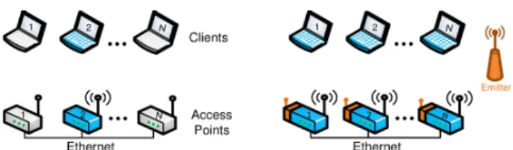
Fig. 8—Traditional AP deployments (left) vs. Distributed MIMO (right).
A blue node indicates an active transmitter or receiver. With traditional Wi-Fi, only one AP transmits at any time in a given channel. In contrast, with AirShare, multiple APs transmit to multiple clients at the same time in the same channel, thereby scaling network throughput with the number of APs.
5.1 Distributed MIMO with AirShare
MIMO beamforming allows a single MIMO node with n antennas to transmit n concurrent packets to n independent clients without interference. Let xi be the data intended for
client i, ~x the vector[x1. . . xn] , and M the channel matrix from
the n-antenna MIMO transmitter to n clients. The MIMO node transmits M−1~x. The clients receive the vector ~yi = MM−1~x.
Thus, each client receives yi= xi, and obtains its intended data
with no interference from data intended for the other clients. By transmitting n independent data units in a unit of time using a unit of spectrum, the system achieves a multiplexing gain of
n, which translates to a throughput gain that increases linearly with the number of antennas. For a more formal description of MIMO beamforming we refer the reader to [29].
Distributed MIMO beamforming enables independent trans-mitters to act as if they were antennas on a single virtual MIMO node. Hence, n single antenna transmitters can use distributed MIMO to deliver n packets to n independent clients, using the same above equations. However for n independent transmitters to act as if they were antennas on a single node, they need to transmit coherently without CFO between them.
While the theory of distributed MIMO has been around for many years, practical implementations have emerged re-cently [15], [10]. These systems transmit training signals to estimate the rotation due to CFO. They then correct for the impact of the CFO on the channel estimates from different transmitters by applying a time-dependent inverse rotation to the transmitted symbols. These algorithms are OFDM specific, and deeply intertwined with the details of the baseband system. In contrast, with AirShare, the nodes have a shared reference, which eliminates the need for phase tracking and compensation altogether. It frees the designer from having to think through the interaction of OFDM and coherent transmission, and pro-vides a technology-independent design. In the next section, we reproduce the distributed MIMO system in [15] but after eliminating any phase tracking and compensation procedures, and providing the nodes with AirShare clock recipients. The results show that the system continues to operate correctly delivering the gains of distributed MIMO but without the need for phase tracking or compensation.
Evaluation of Distributed MIMO with AirShare We place
an AirShare emitter in our testbed. We also place USRPs with AirShare recipients to act as APs and clients in our testbed. Similar to the scenario in [15], we assume that transmitters use the back-end Ethernet to obtain the packets intended for all clients. Also like [15], we use SourceSync [30] to estimate when the nodes should transmit jointly their beamformed data. We evaluate distributed MIMO with AirShare in three dif-ferent SNR regimes: low (5-10 dB), medium (10-16 dB), and
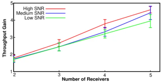
2 3 4 5 1 2 3 4 5 Number of Receivers T h ro u g h p u t G a in High SNR Medium SNR Low SNR
Fig. 9—Distributed MIMO using AirShare. AirShare’s throughput gain
increases linearly with the number of transmitter-receiver pairs in the network. high (> 16 dB). Since USRPs cannot perform carrier sense due to high software latency, we evaluate traditional 802.11 by scheduling each transmitter so that it gets its fair share of the medium. We repeat the experiment for different node placements and different number of transmitter-receiver pairs. Fig. 9 plots the throughput gain obtained by distributed MIMO using AirShare as a function of the number of trans-mitting APs, for different SNR ranges. We see that AirShare enables the wireless network throughput to scale with the number of transmitter-receiver pairs, for a gain of 3.95−4.61× across the range of SNRs. This is because, with traditional 802.11, only one transmitter-receiver pair is active at any time irrespective of the number of transmitters. In contrast, distributed MIMO enables all transmitters to transmit jointly to their desired receivers without interfering with each other, and achieving throughput proportional to the number of active transmitters. This shows that, with AirShare, distributed MIMO systems can achieve results similar to prior work [15] but with-out the need for phase tracking and compensation algorithms.
5.2 Distributed Rate Adaptation for Wireless Sensors
Sensors typically support only a single modulation scheme, such as on-off keying, BPSK, or QPSK [31]. The modulation supported is low rate so as to ensure that the sensors can com-municate even when channel conditions are adverse. Further, sensors avoid supporting high rate (dense) modulations such as 16-QAM, 64-QAM etc., because these modulations require linear transmitter power amplifiers that consume significant power. As a result, wireless sensors do not utilize the wireless channel efficiently. In particular, wireless sensors cannot take advantage of a good channel to send at dense modulation that packs multiple bits into each transmitted symbol.
One can imagine exploiting channel conditions through distributed rate adaptation across the network to overcome the absence of the ability of any single node to adapt its rate. Prior work [16] has proposed such distributed rate adaptation in the context of RFID networks. Specifically, multiple RFID nodes can transmit simultaneously and the receiver receives a collided transmission. Consider, for instance, the case in Fig. 7(b), where 3 nodes, each using BPSK (i.e. +1 or -1), transmit simultaneously. Let the channel between the nodes and the sink be h1, h2 and h3 respectively. In such a case, the
receiver will receive one of 8 points, h1+ h2+ h3, h1+ h2− h3, h1−h2+h3, etc. As can be seen from the figure, the receiver can
decode the individual transmissions from all three transmitters using a single collided transmission, if the channel conditions are sufficiently good. If not, it can simply continue to receive additional transmissions and combine these multiple receptions
Sensors Sink 2 3 Se n so r ID s 1 N 1 3 N Time Slots 2 Emitter 1 2 3 N 1 4 5 3 7 Time Slots 1 2 N Se n sor ID s
Fig. 10—Traditional Sensor Networks (left) vs. Distributed Rate Adapta-tion (right). A blue node indicates an active sensor. With tradiAdapta-tional sensor
networks, only one sensor transmits at a time. In contrast, AirShare-equipped sensors perform distributed rate adaptation by transmitting simultaneously. This enables decoding data from multiple sensors in a single joint transmission, and consumes significantly fewer than N slots to transmit data from all N sensors.
20-25 16-24 12-18 5-12 5-20 0 40 80 SNR (dB) T h ro u g h p u t ( K b p s )
This Work TDMA 120
Fig. 11—Channel Quality versus Throughput for Distributed Rate Adap-tation. AirShare enables distributed rate adaptation for wireless sensors.
till it can decode the transmitted signals. Such a system will effectively achieve a distributed rateless code across the nodes in the RFID network. We refer the reader to [16] for full details of the transmission protocol, and the receiver algorithm to decode the distributed sparse rateless code.
The protocol from [16] described above is designed specif-ically for RFID networks. RFIDs, however, do not have inde-pendent oscillators; they transmit by reflecting a carrier signal from a single device, and hence do not suffer from CFOs relative to each other. In contrast, general wireless devices,
e.g. sensors, have independent oscillators, which they use for transmission. As a result, transmissions from different nodes rotate relative to each other, and collide in different ways across time. Consequently, as can be seen in Fig. 7(a), the joint con-stellation formed by the collisions experiences different rotation and scaling over time, preventing the receiver from decoding the transmitted bits from multiple collision receptions.
AirShare eliminates the problem of differing frequency off-sets across sensors. In particular, when each sensor is equipped with an AirShare recipient, their oscillators are driven by the shared wireless clock and hence they do not have any offset relative to each other. The sensors can therefore perform joint transmission and enable the sink to decode, similar to the case of RFID networks described above.
Evaluation of Distributed Rate Adaptation with AirShare:
As in other experiments, we deploy an AirShare emitter in the testbed. We deploy 6 USRPs equipped with AirShare implementing ZigBee and acting as sensors, and one USRP with AirShare acting as a sink. We run 100 experiments for a variety of node locations. We compare distributed rate adaptation with AirShare with TDMA where only one sensor transmits at a time, and the different sensors transmit one after the other. We evaluate both schemes in various SNR ranges.
Fig. 11 plots the throughput of distributed rate adaptation using AirShare, and of traditional TDMA, for different SNR
ranges. Distributed rate adaptation achieves 1.64− 3× the throughput of TDMA. Since TDMA cannot exploit good chan-nel conditions to increase its transmission rate, its throughput is constant independent of SNR. In contrast, distributed rate adaptation can exploit good channel conditions by allowing the receiver to decode multiple simultaneous transmitters from a single collision. Since the receiver decodes more simultaneous transmitters as the SNR increases, the throughput gain of distributed rate adaptation increases with the average SNR of the network, similar to how the throughput of traditional rate adaptation increases with increasing link SNR.
6
R
ELATEDW
ORKThe most straightforward approach for sharing the clock is to connect the clock input on all nodes to a single external clock via wires. While this approach eliminates CFO and phase drift, it also prevents mobility and effectively trans-forms the nodes to one device with components connected via wires. Concurrently to our work, the authors of [32] proposed using powerlines to distribute a shared clock to the nodes. However, such a design does not address mobile nodes or battery operated sensors. Alternatively, one may equip each node with a GPS disciplined oscillator (GPSDO) or radio-controlled clock. Radio-radio-controlled clocks [33] have 2-6ppm drift (i.e., a CFO of 5-14KHz at 2.4GHz carrier), which is acceptable for wristwatches or clocks, but inadequate for coherent transmission [33]. GPSDOs are accurate but cost 100s of dollars and consume 1-10W [13], [14], making them unsuitable for sensors or even APs. Also, GPSDOs do not work indoors. In contrast, AirShare presents a wireless clock that is simple, low-power and low-cost, and can be used in sensors and APs, both for indoor and outdoor scenarios.
Finally, some prior work [15], [10] enables coherent trans-mission for distributed MIMO by designing algorithms to esti-mate and correct for phase offset between nodes. However, they are designed specifically for OFDM systems in the context of distributed MIMO. In contrast, AirShare’s use of a shared clock provides an abstraction for distributed coherent transmission that is independent of technology (WiFi, Zigbee, etc.), or application (distributed MIMO, distributed modulation, etc.)
7
C
ONCLUSIONThis paper presents AirShare, a system that enables dis-tributed coherent transmission from independent wireless nodes. By sharing a single reference clock across nodes, AirShare provides a coherent radio abstraction that enables im-plementation of distributed PHY algorithms such as distributed MIMO, and distributed sensor rate adaptation. We believe that AirShare can serve as a building block that brings a large body of distributed information theoretic schemes closer to practice.
Acknowledgments:This research is supported by NSF. We thank members of the MIT Center for Wireless Networks and Mobile Computing: Amazon.com, Cisco, Google, Intel, Mediatek, Microsoft, and Telefonica for their interest and support.
R
EFERENCES[1] A. Ozgur, R. Johari, D. Tse, and O. Leveque, “Information-theoretic operating regimes of large wireless networks,” Info. Theory Trans., 2010.
[2] O. Somekh and S. Shamai, “A shannon-theoretic view of wyner’s multiple-access cellular channel model in the presence of fading,” in IEEE Int. Symp. on Info. Theory, Aug 1998.
[3] A. Wyner, “Shannon-theoretic approach to a gaussian cellular multiple-access channel,” IEEE Trans. on Info. Theory, 1994.
[4] A.-s. Hu and S. D. Servetto, “dFSK: Distributed frequency shift keying modulation in dense sensor networks,” in IEEE ICC, 2004.
[5] Y. Ji, C. Stefanovic, C. Bockelmann, A. Dekorsy, and P. Popovski, “Characterization of coded random access with compressive sensing based multi-user detection,” CoRR, vol. abs/1404.2119, 2014. [6] W. Bajwa, J. Haupt, A. Sayeed, and R. Nowak, “Compressive wireless
sensing,” in Information Processing in Sensor Networks, 2006. IPSN 2006. The Fifth International Conference on, 2006, pp. 134–142. [7] B. Nazer and M. Gastpar, “The case for structured random codes in
network capacity theorems,” European Trans. on Telecomm., 2008. [8] S. H. Lim, Y.-H. Kim, A. El Gamal, and S.-Y. Chung, “Noisy network
coding,” IEEE Trans. on Info. Theory, 2011.
[9] I. Maric, N. Liu, and A. Goldsmith, “Encoding against an interferer’s codebook,” in Allerton Conference, 2008.
[10] H. V. Balan, R. Rogalin, A. Michaloliakos, K. Psounis, and G. Caire, “Airsync: Enabling distributed multiuser mimo with full spatial multi-plexing,” IEEE/ACM Trans. on Networking, 2013.
[11] K. Chintalapudi, B. Radunovic, H. V. Balan, M. Buettener, S. Yerramalli, V. Navda, and R. Ramjee, “wifi-nc:wifi over narrow channels.” NSDI’12. [12] Ettus, Universal Software Radio Peripheral, http://www.ettus.com. [13] Jackson Labs, Fury GPSDO, http://jackson-labs.com/.
[14] Trimble, Thunderbolt GPSDO, trimble.com/timing/thunderbolt-e.aspx. [15] H. Rahul, S. S. Kumar, and D. Katabi, “Megamimo: Scaling wireless
capacity with user demand,” in SIGCOMM, 2012.
[16] J. Wang, H. Hassanieh, D. Katabi, and P. Indyk, “Efficient and reliable low-power backscatter networks,” SIGCOMM, 2012.
[17] Abracon “Crystal Oscillator”, www.abracon.com/Resonators/abm3c.pdf. [18] FCC, “FCC online table of frequency allocation, April 16, 2013”. [19] C. A. Balanis, Antenna theory: analysis and design. Wiley, 2012. [20] P. Baronti, P. Pillai, V. W. Chook, S. Chessa, A. Gotta, and Y. F. Hu,
“Wireless sensor networks: A survey on the state of the art and the 802.15. 4 and ZigBee standards,” Computer Communications, 2007. [21] C. A. Boano, M. Z´u˜niga, J. Brown, U. Roedig, C. Keppitiyagama, and
K. R¨omer, “Templab: a testbed infrastructure to study the impact of temperature on wireless sensor networks,” in ACM/IEEE ISPN, 2014. [22] HP, “Fundamentals of quartz oscillators,” Appl. note 200, Tech. Rep. [23] Maxim Integrated, “VHF/UHF Low-Noise Amplifiers.”,
http://datasheets.maximintegrated.com/en/ds/MAX2664-MAX2665.pdf. [24] Cisco, “Cisco Aironet 2600 Access Point”, http://www.cisco.com/en/US/ prod/collateral/wireless/ps5678/ps12534/data\ sheet\ c78-709514.pdf. [25] Texas Instruments, “SoC Solution for 2.4 GHz IEEE 802.15.4 and
ZigBee Applications.”, http://www.ti.com/lit/ds/symlink/cc2530.pdf. [26] FCC, Subpart H: Regulations for Unlicensed Television Band Devices. [27] S. Y. Seidel and T. S. Rappaport, “914 mhz path loss prediction models for indoor wireless communications in multifloored buildings,” IEEE Trans. on Antennas and Propagation, 1992.
[28] M. Speth, S. A. Fechtel, G. Fock, and H. Meyr, “Optimum receiver design for wireless broad-band systems using ofdm. i,” IEEE Trans. on Communications, 1999.
[29] D. Tse and P. Vishwanath, Fundamentals of Wireless Communications. Cambridge University Press, 2005.
[30] H. Rahul, H. Hassanieh, and D. Katabi, “Sourcesync: A distributed wireless architecture for exploiting sender diversity,” SIGCOMM, 2010. [31] S. C. Ergen, “ZigBee/IEEE 802.15.4 summary,” http://pages.cs.wisc.edu/
∼suman/courses/838/papers/zigbee.pdf, 2004.
[32] V. Yenamandra and K. Srinivasan, “Vidyut: exploiting power line infrastructure for enterprise wireless networks,” in SIGCOMM, 2014. [33] NIST., “Radio Station WWVB,” http://tf.nist.gov/general/pdf/2429.pdf.