Publisher’s version / Version de l'éditeur:
Vous avez des questions? Nous pouvons vous aider. Pour communiquer directement avec un auteur, consultez la première page de la revue dans laquelle son article a été publié afin de trouver ses coordonnées. Si vous n’arrivez pas à les repérer, communiquez avec nous à PublicationsArchive-ArchivesPublications@nrc-cnrc.gc.ca.
Questions? Contact the NRC Publications Archive team at
PublicationsArchive-ArchivesPublications@nrc-cnrc.gc.ca. If you wish to email the authors directly, please see the first page of the publication for their contact information.
https://publications-cnrc.canada.ca/fra/droits
L’accès à ce site Web et l’utilisation de son contenu sont assujettis aux conditions présentées dans le site LISEZ CES CONDITIONS ATTENTIVEMENT AVANT D’UTILISER CE SITE WEB.
IOP Conference Series: Materials Science and Engineering, 418, 2018-09-01
READ THESE TERMS AND CONDITIONS CAREFULLY BEFORE USING THIS WEBSITE. https://nrc-publications.canada.ca/eng/copyright
NRC Publications Archive Record / Notice des Archives des publications du CNRC :
https://nrc-publications.canada.ca/eng/view/object/?id=0cb6571a-5346-43ac-bfda-109f987a0014 https://publications-cnrc.canada.ca/fra/voir/objet/?id=0cb6571a-5346-43ac-bfda-109f987a0014
NRC Publications Archive
Archives des publications du CNRC
This publication could be one of several versions: author’s original, accepted manuscript or the publisher’s version. / La version de cette publication peut être l’une des suivantes : la version prépublication de l’auteur, la version acceptée du manuscrit ou la version de l’éditeur.
For the publisher’s version, please access the DOI link below./ Pour consulter la version de l’éditeur, utilisez le lien DOI ci-dessous.
https://doi.org/10.1088/1757-899X/418/1/012127
Access and use of this website and the material on it are subject to the Terms and Conditions set forth at
Stamping of high performance thermoplastic composite intrusion
beams
IOP Conference Series: Materials Science and Engineering
PAPER • OPEN ACCESS
Stamping of high performance thermoplastic composite intrusion beams
To cite this article: D Trudel-Boucher and M F Champagne 2018 IOP Conf. Ser.: Mater. Sci. Eng. 418 012127View the article online for updates and enhancements.
1
Content from this work may be used under the terms of theCreative Commons Attribution 3.0 licence. Any further distribution of this work must maintain attribution to the author(s) and the title of the work, journal citation and DOI.
Published under licence by IOP Publishing Ltd
1234567890‘’“”
International Deep Drawing Research Group 37th Annual Conference IOP Publishing IOP Conf. Series: Materials Science and Engineering 418 (2018) 012127 doi:10.1088/1757-899X/418/1/012127
Stamping of high performance thermoplastic composite
intrusion
beams
D Trudel-Boucher and M F Champagne
National Research Council Canada, Automotive and Surface Transportation Research Center, 75 de Mortagne Blvd., Boucherville (Qc), Canada
Abstract. In this study, an experimental investigation was performed to evaluate the potential
of thermoplastic composites to be used for the fabrication of an automotive intrusion beam using the composite stamping process. To assess the potential of this technology, mechanical properties of several high performance thermoplastic composite materials were first evaluated on coupons. Due to their higher load and displacement at failure, the most promising materials for the fabrication of a composite intrusion beam were found to be glass fibre/polypropylene (GF/PP) and carbon fibre/polyamide 66 (CF/PA66) laminates. Then, stamped intrusion beams were manufactured from these composites using three different stacking sequences. The beams were later tested under three-point flexural loading. For all components, failure occurred at the
attachment points. However, higher properties were obtained for 45 laminates for which
shear-out failure could be avoided. From the load-displacement curves obtained, it can nevertheless be concluded that stamping of thermoplastic composites is promising for the fabrication of intrusion beams, but that further development will be required to avoid failure at the attachment points.
1. Introduction
In recent years, there has been increasing interest in the use of high performance polymer composites in the automotive industry to achieve weight reduction. As evidence of this growing interest, several strategic alliances have been developed between OEM’s and carbon fibre suppliers 1. The main driver for the integration of composites in the automotive industry is the Corporate Fuel Average Efficiency (CAFÉ) regulation that requires fuel consumption of 54.5 mpg (4.3 L/100 km) to be reached by 2025. According to one study 2, the use of lightweight materials such as composites can result in significant fuel consumption reduction along with enormous environmental benefits: trimming the weight of a vehicle by 1 kg results in a 17-20 kg reduction in the amount of CO2 emitted
during the lifetime of that vehicle. A study from Oak Ridge National Laboratory also showed that replacing today’s steel body-in-white (BIW) with an integrated carbon fibre composite structure could result in a 60 percent mass reduction, boosting fuel efficiency by as much as 30 percent 3. This offers significant potential not only for meeting new fuel-economy standards with conventional engines, but also to offset added weight from electric battery packs, fuel-cell storage cylinders and other equipment essential to alternative-powertrain vehicles. However, most manufacturing process adapted to high performance composites do not meet the cycle time targeted by the automotive industry for the high volume production.
2
1234567890‘’“”
International Deep Drawing Research Group 37th Annual Conference IOP Publishing IOP Conf. Series: Materials Science and Engineering 418 (2018) 012127 doi:10.1088/1757-899X/418/1/012127
One of the most promising processes to cost-efficiently manufacture high performance composite components for the automotive industry is the composite stamping process, a process similar to the widely used metal stamping process. One of the key advantages of this technology is the potential to manufacture light weight automotive parts in very short cycle times from continuous fibre thermoplastic composites. In addition, the composite stamping process also offer the potential of being implemented using existing infrastructure, since forming presses are commonly used in the automotive industry. Although this process has been used in the aerospace for several years 4], little work has been done to date on automotive applications.
In this study, an experimental investigation on stamping of an automotive composite intrusion beam is conducted. This component was selected because of the interesting challenges associated with the balance of stiffness, strength and deformation that must be achieved to meet the performance requirements of such a part 5. In order to evaluate the potential of high performance thermoplastic composites to be used for the fabrication of such structural parts, the mechanical behaviour of several high performance composite materials is first investigated by performing flexural tests on coupons. From these small scale tests, the most-promising composite configurations are identified. Then, stamping trials are conducted to manufacture intrusion beams. Finally, flexural tests are conducted on full-scale stamped components to study their mechanical behaviour.
2. Experimental Procedures 2.1. Materials
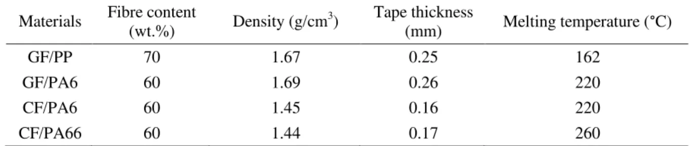
Four continuous fibre thermoplastic composite materials were investigated in this study. These materials consist of glass fibre/polypropylene (GF/PP), glass fibre/polyamide 6 (GF/PA6), carbon fibre/polyamide 6 (CF/PA6) and carbon fibre/polyamide 66 (CF/PA66) composites. The materials considered in this study were all in the form of pre-impregnated thermoplastic unidirectional tapes. Table 1 shows the fibre content, density, thickness and the melting temperature of these composites, as determined by differential scanning calorimetry (DSC).
Table 1. Description of continuous fibre thermoplastic composite materials.
Materials Fibre content
(wt.%) Density (g/cm3) Tape thickness (mm) Melting temperature (°C) GF/PP 70 1.67 0.25 162 GF/PA6 60 1.69 0.26 220 CF/PA6 60 1.45 0.16 220 CF/PA66 60 1.44 0.17 260 2.2. Material characterization
Flexural tests were initially performed on rectangular coupons to identify promising materials and stacking sequences for the fabrication of stamped intrusion beams. To manufacture test specimens, composite tapes were first manually laid-down into a mould according to the desired stacking sequences. The stacks were then compression moulded to produce rectangular panels. During the compression moulding cycle, laminates were heated 40°C above their melting temperatures, held at high temperature for 5 minutes and then cooled to room temperature at a rate of approximately 10 C/min. A constant pressure of 0.7 MPa (100 psi) was applied during the entire moulding cycle. Coupons of 38 mm in width and 250 mm in length were then machined using water jet equipment. An 8 mm diameter hole was machined at each end to fix the specimens into the flexural test jig (Figure 1). Load-displacement curves were then obtained from three-point flexural tests performed at a rate of 20 mm/min using a span of 200 mm. Three stacking sequences were considered for each material, i.e. 0/90, 45 and quasi-isotropic (QI). A detailed description of the lay-up used is provided in Table 2.
3
1234567890‘’“”
International Deep Drawing Research Group 37th Annual Conference IOP Publishing IOP Conf. Series: Materials Science and Engineering 418 (2018) 012127 doi:10.1088/1757-899X/418/1/012127
Figure 1.Three-point flexural test on coupons.
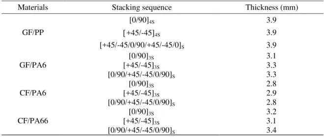
Table 2. Stacking sequences investigated for flexural tests on coupons.
Materials Stacking sequence Thickness (mm)
GF/PP [0/90]4S 3.9 +45/-454S 3.9 [+45/-45/0/90/+45/-45/0]S 3.9 GF/PA6 [0/90]3S 3.1 [+45/-45]3S 3.3 [0/90/+45/-45/0/90]S 3.3 CF/PA6 [0/90]3S 2.8 [+45/-45]3S 2.9 [0/90/+45/-45/0/90]S 2.8 CF/PA66 [0/90]3S 3.2 [+45/-45]3S 3.1 [0/90/+45/-45/0/90]S 3.4
2.3. Composite stamping process
Prior to performing stamping trials, composite sheets were first manufactured. Similarly to what was described earlier, composite tapes were laid-down manually to the desired stacking sequences prior to being compression moulded. Blanks of the proper dimensions were then cut from the produced sheets using water jet cutting.
During the composite stamping process, continuous fibre thermoplastic composite blanks were first heated above the melting temperature of the thermoplastic matrix in an external infrared (IR) oven and then rapidly transferred to a press where they were stamped (Figure 2a). Due to rapid cooling of the material during transfer from the oven to the press, pre-heat temperatures were selected to be 50 to 60°C higher than the melting temperatures shown in Table 1. To prevent excessive cooling of the material prior to stamping, a press closing speed of 500 mm/s was used. The 1000 Ton forming platform used to perform the composite stamping trials is shown in Figure 2b.
4
1234567890‘’“”
International Deep Drawing Research Group 37th Annual Conference IOP Publishing IOP Conf. Series: Materials Science and Engineering 418 (2018) 012127 doi:10.1088/1757-899X/418/1/012127
(a) (b)
Figure 2. (a) Schematic representation of the composite stamping process and
(b) NRC’s composite stamping platform.
2.4. Characterization of stamped intrusion beams
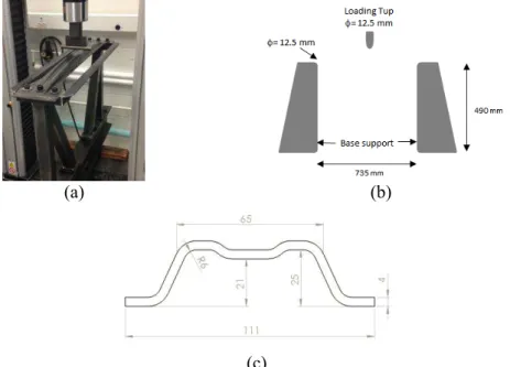
The mechanical behaviour of the stamped intrusion beams was investigated by performing three-point bending tests. To conduct these tests, a test jig was manufactured (Figure 3) and installed into an Instron universal testing apparatus. Experiments were conducted at a cross-head speed of 380 mm/min. From the tests, the load-displacement curves were obtained. Cross-section of tested intrusion beam is also illustrated in Figure 3.
(a) (b)
(c)
Figure 3. (a) Flexural test on stamped composite intrusion beam, (b) schematic representation of experimental set-up and (c) cross-section of composite intrusion beam at mid-span.
3. Results and discussion
3.1. Selection of promising materials
3.1.1. Glass fiber composites. Results of tests performed on glass fibre composite materials, using the experimental configuration in Figure 1, are described in this section (Figure 4 and Figure 5). As shown in Figure 4, significantly different mechanical behaviours were measured for the GF/PP composites depending on their stacking sequence. For ±45 lay-up, almost linear behaviour is observed up to
5
1234567890‘’“”
International Deep Drawing Research Group 37th Annual Conference IOP Publishing IOP Conf. Series: Materials Science and Engineering 418 (2018) 012127 doi:10.1088/1757-899X/418/1/012127
failure. Much larger displacement at failure is also obtained for this configuration. However, lower stiffness is measured due to absence of fibres along the length of the specimens. For this material configuration also, failure occurred at the attachment point (Figure 6) with multiple delaminations being observed at mid-span. No significant change in fibre orientation could however be measured on the top and bottom surfaces of the tested specimens. This suggests that large deformation was achieved through accumulation of damage in internal plies. As also shown in Figure 4, much smaller displacements at failure were obtained for the 0/90 and quasi-isotropic stacking sequences with only slightly higher displacement at failure being measured for the quasi-isotropic configuration. The higher displacement at failure measured for the quasi-isotropic laminate (relative to the 0/90 lay-up) is likely attributed to the presence of ±45 plies in the lay-up. A similar failure mode was obtained for the (0/90) and quasi-isotropic (QI) configurations. In both cases, failure at mid-span was observed (Figure 7).
Results of flexural tests performed on the GF/PA6 composites are shown in Figure 5. As shown in this figure, smaller displacements at failure are obtained for GF/PA6 composites as compared to those measured for GF/PP composites (Figure 4), even though the PA6 matrix can reach deformation at break in excess of 100% 6. Further study will be required to explain this behaviour. From these results, it is apparent that the more brittle behaviour of the GF/PA6 composites makes them less suitable for the fabrication of intrusion beams. With regards to the failure mode, failure at the attachment point was observed for the (0/90) laminate. For the 45 and quasi-isotropic configurations, failure at mid-span was observed, similarly to what is shown in Figure 7.
Figure 4. Load vs. displacement curves for GF/PP composites.
Figure 5. Load vs. displacement curves for GF/PA6 composites.
Figure 6. Failure of GF/PP composite with ±45 lay-up.
Figure 7. Failure of GF/PP composite with 0/90 lay-up. 0 2000 4000 6000 8000 10000 12000 14000 16000 18000 0 10 20 30 40 50 60 70 Lo ad (N) Displacement (mm) GF/PP - (0/90) GF/PP - (±45) GF/PP - (QI) 0 1000 2000 3000 4000 5000 6000 7000 8000 9000 10000 0 10 20 30 40 50 60 70 Lo ad (N) Displacement (mm) GF/PA6 - (0/90) GF/PA6 - (±45) GF/PA6 - (QI)
6
1234567890‘’“”
International Deep Drawing Research Group 37th Annual Conference IOP Publishing IOP Conf. Series: Materials Science and Engineering 418 (2018) 012127 doi:10.1088/1757-899X/418/1/012127
3.1.2. Carbon fiber composites. Similarly to what was observed for the glass fiber composites (Section 3.1.1), significantly different mechanical behaviors were measured for the carbon fiber composites depending on the polymer matrix and stacking sequences (Figure 8 and Figure 9). For the CF/PA66 composites, larger deformation was obtained for composites having a ±45 lay-up (Figure 8). For this configuration, failure occurred in the span of the specimens by separation of the plies at multiple interfaces (Figure 10). Similarly to what was found for GF/PP composite, multiple delaminations were also seen at mid-span. In contrast, localized “brittle” failures at mid-span were obtained for the 0/90 and quasi-isotropic (QI) configurations (Figure 11).
Results of flexural tests performed on CF/PA6 composites are shown in Figure 9. As shown in this Figure, similar mechanical behaviours were obtained for 0/90 and quasi-isotropic configurations. As could be anticipated, much higher deformation was again obtained for the ±45 stacking sequence. However, for that particular stacking sequence, the displacement at failure obtained for CF/PA6 composite was seen to be significantly lower than the one measured for the CF/PA66 composite. It thus appears that CF/PA6 is less suitable for the fabrication of composite intrusion beams since large deformation is required for side impact protection [5]. For all CF/PA6 laminates, localized failure at mid-span was observed similarly to what is shown in Figure 11. In contrast, failure occurred by separation of plies at multiple interfaces for the CF/PA66 composite with the 45 stacking sequence, as mentioned previously. This difference in failure mode probably explains the significantly different displacement at failure obtained for CF/PA66 and CF/PA6 composites.
Figure 8. Load vs. displacement curves for CF/PA66 composites.
Figure 9. Load vs. displacement curves for CF/PA6 composites.
Figure 10. Failure of CF/PA66 composite with ±45 lay-up.
Figure 11. Failure of CF/PA66 composite with 0/90 lay-up. 0 2000 4000 6000 8000 10000 12000 14000 16000 18000 0 10 20 30 40 50 60 70 Lo ad (N) Displacement (mm) CF/PA66 - (0/90) CF/PA66 - (±45) CF/PA66 - (QI) 0 1000 2000 3000 4000 5000 6000 7000 8000 9000 10000 0 10 20 30 40 50 60 70 Lo ad (N) Displacement (mm) CF/PA6 - (0/90) CF/PA6 - (±45) CF/PA6 - (QI)
7
1234567890‘’“”
International Deep Drawing Research Group 37th Annual Conference IOP Publishing IOP Conf. Series: Materials Science and Engineering 418 (2018) 012127 doi:10.1088/1757-899X/418/1/012127
3.2. Stamping of intrusion beam
3.2.1. Stamping trials. Stamping of composite intrusion beams was performed in this work using GF/PP and CF/PA66 composites, since these materials displayed the highest loads and displacements at failure during the identification of the most-promising materials (Section 3.1). Stamping trials were performed for three stacking sequences, i.e. 15, 30 and 45. These stacking sequences were selected because most-promising results were obtained in the previous section for laminates solely composed of off-angle plies (45 stacking sequence).
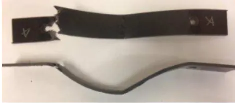
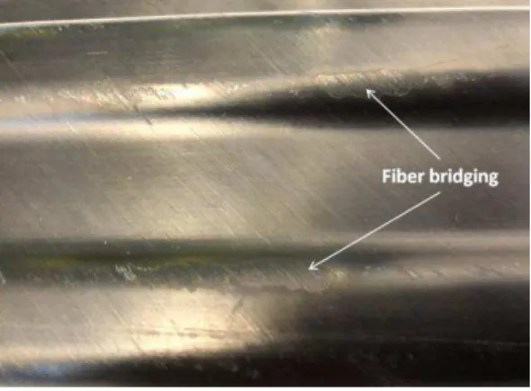
One of the biggest challenges associated with the composite stamping process is related to the deformation of the laminate since, unlike metallic sheets, a continuous fibre reinforced composite can be considered as essentially inextensible. For composites, the dominant deformation mechanisms are thus interlaminar shear and intralaminar shear. The former involves fabric plies slipping on top of each other while in the latter the fibres of successive plies rotate against each other. In this study, stamping trials were generally successful with the materials being able to deform to accommodate the geometry of the beam. However, as shown in Figure 12, fibre bridging could be observed on the surface of the stamped intrusion beams. This can be attributed to the high stiffness and low elongation of the reinforcing fibres which cannot conform to the small radius when in tension. Further work will be required to determine if such defects can be eliminated during the stamping process.
Figure 12. Fibre bridging on stamped thermoplastic composite intrusion
beam.
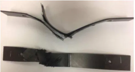
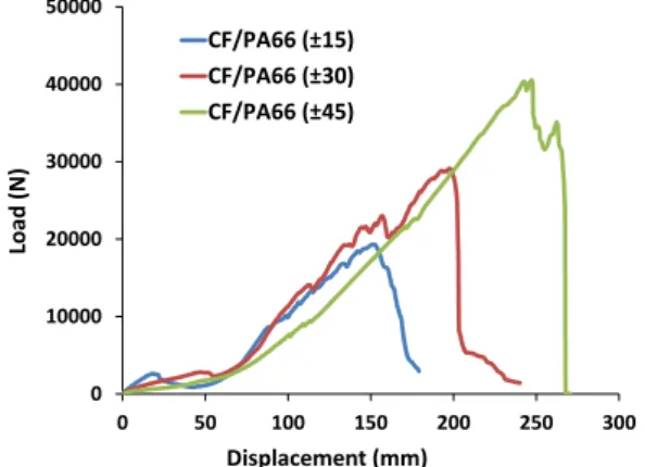
3.2.2. Mechanical behaviour of stamped composite intrusion beams. Results of tests performed on stamped intrusion beams are shown in Figure 13 and Figure 14 for GF/PP and CF/PA66 laminates, respectively. As shown in these figures, similar trends are obtained for both materials with maximum loads and maximum displacements increasing with increasing fibre angle. Change of failure mode is also observed with increasing fibre angle. For 15 and 30 laminates, shear tear-out failure at the attachment point is observed (Figure 15), which probably explains the lower performance achieved for these configurations. For 45 laminates, failure also occurred at the attachment point, but across the mounting point (Figure 16). Nevertheless, the displacement and loads at failure obtained in this study for the 45 laminates suggest that thermoplastic composites are promising materials for the development of structural automotive applications, such as intrusion beams, where the combination of high load and high deformation are required. However, additional work will be performed in the future to prevent premature failure of the stamped intrusion beam at the attachment point.
8
1234567890‘’“”
International Deep Drawing Research Group 37th Annual Conference IOP Publishing IOP Conf. Series: Materials Science and Engineering 418 (2018) 012127 doi:10.1088/1757-899X/418/1/012127
Figure 13. Load vs. displacement curves for GF/PP intrusion beams.
Figure 14. Load vs. displacement curves for CF/PA66 intrusion beams.
Figure 15. Failure of stamped CF/PA66 intrusion
beam with 15 stacking sequence. Figure 16. beam with 45 stacking sequence. Failure of stamped GF/PP intrusion
4. Conclusions
An experimental investigation was performed to evaluate the potential of thermoplastic composites to be used for the fabrication of composite intrusion beam using the composite stamping process. To assess the potential of high performance thermoplastic composite materials, mechanical properties were first evaluated. From these tests, GF/PP and CF/PA66 laminates were identified as most-promising materials due to their higher load and displacement at failure. Stamped composite components were then manufactured from GF/PP and CF/PA66 laminates and tested under three-point flexural loading. Results showed that high loads and displacement at failure could be achieved, but that further work is necessary to avoid premature failure at the attachment point. From the results obtained in this study, it can be concluded that stamping of thermoplastic composites is a promising technology for the fabrication of structural automotive components such as intrusion beams.
5. References
[1] Mazumdar S 2016 State of the composite industry Composites Manufacturing 32 19
[2] Composite Materials Market for Automotive by Material Type (PMC, MMC, & CMC), Application & their Sub-Components (Structural, Powertrain, Interior, Exterior, & Others), Vehicle Type (PC, LCV, HCV, & Rolling Stock), & by Region-Global Forecast to 2020 2015 (Northbrook: MarketsandMarkets)
[3] Boeman R G and Johnson N L Development of a cost competitive, composite intensive, body-in-white 2002 Proc. Future car congress (Arlington) (Warrendale: SAE International)
[4] Offringa A R Thermoplastic composites – Rapid process applications 1996 Composites: Part A
27A 329
[5] Jones J 1992 Laboratory test Procedure for FMVSS 214S (Static) side impact protection (Washington DC: NHTSA)
[6] Mark J E (1999) Polymer data handbook (Oxford: Oxford University Press) 0 10000 20000 30000 40000 50000 0 50 100 150 200 250 300 Lo ad (N) Displacement (mm) GF/PP (±15) GF/PP (±30) GF/PP (±45) 0 10000 20000 30000 40000 50000 0 50 100 150 200 250 300 Lo ad (N) Displacement (mm) CF/PA66 (±15) CF/PA66 (±30) CF/PA66 (±45)