HAL Id: hal-01760319
https://hal.archives-ouvertes.fr/hal-01760319
Submitted on 6 Apr 2018
HAL is a multi-disciplinary open access
archive for the deposit and dissemination of
sci-entific research documents, whether they are
pub-lished or not. The documents may come from
teaching and research institutions in France or
abroad, or from public or private research centers.
L’archive ouverte pluridisciplinaire HAL, est
destinée au dépôt et à la diffusion de documents
scientifiques de niveau recherche, publiés ou non,
émanant des établissements d’enseignement et de
recherche français ou étrangers, des laboratoires
publics ou privés.
the nanotube diameter
Matthieu Chorro, Axel Delhey, Laure Noé, Marc Monthioux, Pascale Launois
To cite this version:
Matthieu Chorro, Axel Delhey, Laure Noé, Marc Monthioux, Pascale Launois. Orientation of C70
molecules in peapods as a function of the nanotube diameter.
Physical Review B: Condensed
Matter and Materials Physics (1998-2015), American Physical Society, 2007, 75 (3), pp.035416.
�10.1103/PhysRevB.75.035416�. �hal-01760319�
Orientation of C
70molecules in peapods as a function of the nanotube diameter
Matthieu Chorro,1Axel Delhey,1Laure Noé,2Marc Monthioux,2and Pascale Launois1,*1Laboratoire de Physique des Solides, UMR CNRS 8502, bât. 510, Université Paris Sud, 91 405 Orsay Cedex, France 2CEMES, CNRS, 29 rue Jeanne Marvig, 31055 Toulouse Cedex 4, France
共Received 28 June 2006; revised manuscript received 14 September 2006; published 17 January 2007兲
Encapsulated C70molecules packed in single-walled carbon nanotubes display different orientations
depend-ing on the nanotube radius. We present x-ray scatterdepend-ing data obtained on a powder of nanotubes filled with C70 molecules. Analytical expressions for calculating the diffraction diagram taking into account fullerene orien-tations are developed. The comparison between calculations and experiments allows us to conclude that the change from the lying to standing orientation—corresponding to the molecule long axis parallel and perpen-dicular to the tube axis, respectively—takes place when nanotubes reach a diameter of about 1.42 nm. Energy calculations are performed using a Lennard-Jones共6-12兲 potential, leading to a calculated reorientation diam-eter in good agreement with that ddiam-etermined experimentally.
DOI:10.1103/PhysRevB.75.035416 PACS number共s兲: 61.10.Eq, 61.48.⫹c
I. INTRODUCTION
The observation of C60fullerene molecules inside single-walled carbon nanotubes共SWNT兲 in 1998 共Ref.1兲 led to the
synthesis of new hybrid carbon nanostructures, as reviewed in Ref. 2. These nanostructures, termed peapods, are com-monly described as one-dimensional periodic chains of fullerenes Cn 共n=60, 70, etc.兲 inside the nanotubes. Nano-tubes possess exceptional electronic or mechanical properties,3,4 whose tuning by filling with fullerenes is a most interesting perspective. Indeed, modification of the lo-cal electronic structure or improvement in mechanilo-cal prop-erties have been demonstrated for C60 peapods.5,6 C70 pea-pods have been less studied than C60 ones up to now, but their structural and physical properties should be richer due to the ellipsoidal shape of the C70 fullerene as compared to the spherical one of C60. Using electron diffraction, Hirahara and co-workers evidenced polymorphic packing structures in C70 peapods.7 Two different orientations have been found experimentally depending on the nanotube diameter: the ly-ing orientation where the molecule long axis is parallel to the tube axis, and the standing orientation, corresponding to molecule long axis perpendicular to the tube axis.7–9 Inter-estingly, theoretical investigations point towards the depen-dency of electron states with the molecule orientation.10,11
The goal of the present work is to determine the nanotube diameter value beyond which the change from the lying to standing orientation occurs, which is not yet known pre-cisely. The reorientation diameter is deduced from x-ray scattering measurements. An interesting property of x-ray experiments, which are made on macroscopic samples, is that contribution of out-of-statistic objects 共defective nano-tubes, etc.兲 is negligible. Analytical expressions of the scat-tering law taking into account molecular orientations have been developed, allowing us to simulate the measured x-ray diffractograms. The nanotube diameter distribution, distances in between fullerene centers of mass and fullerene orienta-tions are deduced from comparison between measurements and simulations. The reorientation diameter obtained from x-ray experiments will be discussed with respect to available experimental and theoretical results in the literature. As un-derlined in Ref.12, dispersion forces are notoriously difficult to determine theoretically and experimental data are needed
as benchmarks guiding the choice of models. We have per-formed energy calculations using a Lennard-Jones 共6-12兲 potential.13They allow to determine a reorientation diameter value in good agreement with that determined experimen-tally. It is thus shown that the Lennard-Jones potential is effective for the calculation of fullerene orientations inside nanotubes.
II. EXPERIMENT A. Experimental part
SWNTs used in this study 共Fig. 1, left-hand side兲 were
supplied by NANOCARBLAB共Russia兲. They were prepared following the electric arc route共Ni+Y catalysts兲 then exten-sively purified via successive oxidation treatments including soaking in HNO3, annealing in air and freeze drying. The purification procedure was severe enough to create openings of the SWNTs. The as-received material was disposed into a
FIG. 1. 共Left-hand side兲 Transmission electron microscopy im-ages of SWNTs. Low magnification, SWNT bundles are shown along with empty polyaromatic carbon shells. 共Right-hand side兲 High resolution transmission electron microscopy image of a C70
@SWNT peapod bundle. The resolution is not sufficient to distin-guish between lying and standing C70molecules.
quartz ampoule along with C70 powder 共Alfa Aesar, more 98% pure兲. The amount of C70 was calculated so that the fullerene vapor pressure was about 1 atmosphere at the fill-ing temperature. To outgas the whole material, the ampoule was evacuated 共primary vacuum兲 while being heated up to 200 ° C in a sand bath for 15– 30 minutes then filled with argon, cycled three times. It was after heating in a tubular furnace up to 500 ° C for 24 hours, to allow for the sublima-tion of the C70powder and for the insertion of the molecules inside nanotubes. The ampoule was eventually annealed un-der dynamic primary vacuum up to 800 ° C for 1 hour to get rid of residual 共noninserted兲 C70. From TEM images, the filling rate appears quite high共Fig.1, right-hand side兲.
SWNT and C70 peapod powders were placed inside Lin-demann glass capillaries of 1 mm diameter. Diffraction pat-terns were recorded in transmission on a planar imaging plate, using a rotating anode device delivering Cu K␣ wave-length 共=1.5418 Å兲 after confocal parabolic W/Si multilayer mirrors. Experiments were performed under vacuum to minimize contamination due to air scattering. Typical recording times are of about 24 hours.
B. X-ray scattering results
Diffraction patterns obtained for both SWNT and C70 pea-pod samples are shown in Fig.2.
The first diffraction peak of the SWNT pattern is observed at wave vector Q⯝0.41 Å−1, a typical value for nanotube powders produced by the electric-arc method.14,15 Single-walled nanotubes are packed in small crystalline bundles. The peak sited at Q⯝0.41 Å−1corresponds to the 10 reflec-tion from the bidimensional hexagonal bundles lattice.16 Higher order diffraction peaks are visible up to 1.6 Å−1. The intense peaks situated around 1.85 Å−1are coming from pol-yaromatic共graphene-based兲 impurities. Strong intensities at small wave vectors, below 0.4 Å−1, often measured in SWNT samples, may be associated with sample porosity.
In the case of peapods, one observes a strong diminution of the intensity of the 10 peak. This peak is very sensitive to molecular encapsulation17,18and its diminution allows one to estimate the filling rate of the nanotubes by the C70 mol-ecules. The higher order diffraction peaks from the bundle lattices are clearly visible between 0.8 and 1.6 Å−1, showing that the filled nanotubes are still well crystallized in hexago-nal bundles. Two additiohexago-nal peaks, at wave-vector values Q ⯝0.57 Å−1 and 0.63 Å−1, are also present. A similar result was obtained in a previous x-ray diffraction study performed by Maniwa and co-workers on peapods made from SWNTs synthesized by the laser ablation method.19 Following the well-known relation Q = 2/ L, the two additional diffraction peaks are found to correspond to distances L⯝11 Å = 1.1 nm and 10 Å = 1 nm in direct space, respectively. The C70 molecule has an ellipsoidal shape with short and long
FIG. 2. Room temperature diffraction patterns of SWNTs共upper curve, open circles兲 and C70peapods共lower curve, open circles兲. The curves are translated vertically for the sake of clarity. Diffuse scattering from the glass capillary—centered around 1.7 Å−1—has been
measured on empty capillaries and substracted to both SWNT and peapod diagrams. Below each experimental curves are represented the simulation共black thick line兲 and the background used for the fit 共small circles兲. Doublets of Miller indices refer to diffraction peaks of the two-dimensional hexagonal bundle lattice. “Gr 002” refers to scattering by graphene-based impurities. The positions of the first order diffraction peaks of the periodic chains of lying and standing C70molecules are indicated by the indexation L and S, respectively. Inset:
axes, respectively, equal to about 0.71 and 0.81 nm. The measured distances roughly correspond to distances in be-tween two lying molecules or two standing ones when the van der Waals distance 共⯝0.3 nm兲 between them is taken into account.7,19 The two additional diffraction peaks ob-served for C70peapod sample can thus be attributed to peri-odic linear arrangements of lying and of standing molecules inside the nanotubes.
III. ANALYTICAL EXPRESSIONS FOR THE SCATTERING LAW
An analytic formula is built up to calculate the scattered intensity of a C70 peapod powder. Analytical descriptions of the diffraction pattern of C60 peapods have been given in Ref.18. Diffraction by C70peapods is more difficult to cal-culate due to orientational effects. The range of investigated wave vectors being smaller than 2 Å−1, homogeneous ap-proximation can be used. We modelize the C70 fullerene as formed of nine circlesof heightand radius R⬜共see Fig.
3and TableI兲.
A. The C70form factor in lying and standing orientations
The molecule form factor can be first calculated in the system 共R
⬘
兲 of the C70 molecule, where the z⬘
axis is the molecule long axis, and then in the system共R兲 of the nano-tube, where the Z axis is the tube axis. The cylindrical coor-dinates of the wave vector Qជ are 共Qz⬘
, Q⬘
⬜,Q⬘
ជ兲 in 共R⬘
兲 and 共Qz, Q⬜,Qជ兲 in 共R兲, as is illustrated in Fig.4. The form fac-tor is the Fourier transform of the molecule electronic den-sity. In the molecule system共R⬘
兲, it thus writesFC 70共Qជ兲 = fc共Q兲
兺
=0 8 nR⬜exp共iQz⬘
兲 ⫻冕
0 2 exp关iQ⬜⬘
R⬜cos共−Q⬘
ជ兲兴d. Integration is performed over each atomic circle 共see Figs.3and4, and TableI兲.is the polar angle of a point M over the circle, R⬜the radius of circle,is its z
⬘
coordinate and n is the linear atomic density along the circle. fc共Q兲 is the scattering form factor of a carbon atom. It follows thatFC70共Qជ兲 = fc共Q兲
冉
N0J0共Q⬜⬘
R0⬜兲 + 2兺
=1 4
Ncos共Qz
⬘
兲J0共Q⬜⬘
R⬜兲冊
, 共1兲Nbeing the number of carbon atoms on circle and J0 the cylindrical Bessel function of order zero
兵
J0共x兲 =21兰02exp关ix sin共t兲兴dt其
. The systems of coordinates共R兲 and 共R⬘
兲 coincide for the lying molecule, and one thus directly obtains the lying form factor in共R兲 asFC70Lying共Q,Qz兲 = fc共Q兲
冉
N0J0共冑
Q2− Qz 2 R0⬜兲 + 2兺
=1 4 Ncos共Qz兲J0共冑
Q2− Qz 2R ⬜兲冊
. 共2兲 For the standing case, the molecule long axis is in the planeTABLE I. The C70 molecule characteristics within
homoge-neous approximation. The index label the circles, and R⬜refer to their coordinate along the molecule long axis and to their radii, respectively. Nis the number of carbon atom and nis the linear atomic density. 共nm兲 R⬜共nm兲 N n共atom/Å兲 0 0 0.3565 10 0.446 1 0.1197 0.3461 10 0.460 2 0.2449 0.3005 10 0.529 3 0.3235 0.2401 5 0.331 4 0.3983 0.1243 5 0.640 5 −0.1197 0.3461 10 0.460 6 −0.2449 0.3005 10 0.529 7 −0.3235 0.2401 5 0.331 8 −0.3983 0.1243 5 0.640
FIG. 3. The C70 molecule: atomic model and homogeneous
approximation.
FIG. 4. Representation of the coordinates used in the calcula-tion:共a兲 in the molecule system 共R⬘= 0x⬘y⬘z⬘兲 and 共b兲 in the
nano-tube system共R=0XYZ兲. In 共b兲, the orientation of the molecular long axis 0z⬘and of the molecule system of coordinates共0x⬘y⬘z⬘兲 in the
共0xy兲, making the angle mol with 0x 共Fig. 4兲. Using rela-tions between coordinates of the wave vector Qជ in the
sys-tems共R兲 and 共R
⬘
兲, one obtains for the standing form factor in 共R兲,FC70Standing共Q,Qz,mol兲 = fc共Q兲
冉
N0J0关冑
Q2sin2共Qជ−mol兲 + Qz 2 cos2共Qជ−mol兲R0⬜兴 + 2兺
=1 4 Ncos关冑
Q2− Qz 2cos共Qជ−mol兲兴J0关
冑
Q2sin2共Qជ−mol兲 + Qz 2cos2共Qជ−mol兲R⬜兴
冊
. 共3兲B. Scattered intensity from a powder of C70peapods:
analytical formula
Let us consider nanotubes with diameter⌽T, their length being assumed to be infinite 共the infinite length hypothesis means that nanotube length is large when compared to ex-perimental resolution兲. Nanotubes are assembled into hex-agonal bundles. The nanotube filling rate by fullerenes is p 共0艋p艋1兲. Fullerenes are assumed to form long chains 共longer than resolution兲 inside the nanotubes, which means that the formula derived here should not be used for very small filling rates. Detailed demonstration of the scattered intensity formula is developed in the lying case; it could be easily done by the reader, using the same approach, in the standing case. Spherical approximation will eventually be discussed for comparison.
In the lying case, the form factor of a peapod of length L, containing one C70molecule at half-height, writes
F共Qជ兲 = aTJ0
冉
Q⬜⌽T 2冊
sin共QzL/2兲 QzL/2 + FC70Lying共Qជ兲, where aT= fc共Q兲⌽TLT. fcis the carbon form factor,Tis the density of carbon atoms on the nanotube 共T ⯝0.37 atom/Å2兲, Qz and Q⬜ are the components of the wave vector Qជ along the tube axis and perpendicular to it, Q is its modulus. The form factor is the sum of two terms: a nanotube term and a fullerene term. For a bundle of peapods of length NcL, one obtains
F共Qជ兲 =
兺
i冋
aTJ0冉
Q⬜⌽T 2冊
sin共QzL/2兲 QzL/2+ FC70Lying共Qជ兲exp关iQzTz共i兲兴
册
exp共iQជ⬜Rជi兲 ⫻兺
n=0 Nc−1
exp共iQznL兲, 共4兲
where Rជi is the position of tube i perpendicularly to the bundle axis and Tz共i兲 is the position of a molecule of the chain i along the 0z axis of the nanotube. It will be assumed that there are no correlations in z positions for molecular
chains in different tubes, as discussed theoretically in Ref.
20. Intensity per length unit writes
I共Qជ兲 =
兺
i,j冋
aTJ0冉
Q⬜⌽T 2冊
sin共QzL/2兲 QzL/2 + FC70Lying共Qជ兲exp关iQzTz共i兲兴册
⫻冋
aTJ0冉
Q⬜⌽T 2冊
sin共QzL/2兲 QzL/2 + FC70Lying共Qជ兲exp关− iQzTz共j兲兴
册
exp关iQជ⬜共Rជi− Rជj兲兴1 NcL ⫻
兺
n,m=0 Nc−1 exp关iQz共n − m兲L兴. 共5兲Using the relation lim Nc→⬁ 1 NcLn,m=0
兺
Nc−1 exp关iQz共n − m兲L兴 = 2 L2k=−兺
⬁ ⬁ ␦共Qz− 2k/L兲, where␦共x兲 is the Dirac distribution and where k, n, and m are integers, and averaging over the random variables Tz共i兲, one then gets, for parallel bundles of infinite tubes filled with infinite chains of C70 molecules separated by distance L,ILying共Qជ兲 = 2 L2
再
兺
i,j exp关iQជ⬜共Rជi− Rជj兲兴 ⫻冋
aTJ0冉
Q⬜⌽T 2冊
+ FC70Lying共Qជ兲册
2 ␦共Qz兲 + Nf兺
k=−⬁,k⫽0 ⬁ FC70Lying共Qជ兲2␦共Qz− k2/L兲冎
, 共6兲Nfis the total number of tubes per bundle. The␦共Qz兲 depen-dent term is the Fourier transform of the atomic density pro-jected on a plane perpendicular to the nanotube axis, while the␦共Qz− k2/ L兲 dependent term comes from the periodic-ity of the C70 chain. Note that in principle, the fullerene
chain should not be considered as a one-dimensional 共1D兲 crystal but as a 1D liquid. The rigorous treatment is given in Refs.21 and22for a C60 chain. However, peak widths are found to be extremely narrow, which validates the crystalline approach.
If the filling rate p is not equal to 1, with still long chains of molecules, Eq.共6兲 becomes
ILying共Qជ兲 =2
L2
再
兺
i,j exp关iQជ⬜共Rជi− Rជj兲兴⫻
冋
aTJ0冉
Q⬜⌽T 2冊
+ pFC70Lying共Qជ兲册
2 ␦共Qz兲 + Nf兺
k=−⬁,k⫽0 ⬁ p2FC70Lying共Qជ兲2␦共Qz− 2k/L兲冎
. 共7兲 To obtain now the scattered intensity from a powder of pea-pods, one must average intensities over all orientations of the wave vector Qជ, Ip,Lying共Q兲 = 1 4冕
0 dQជsin共Qជ兲冕
0 2 dQជILying共Qជ兲 共8兲 Note that 兰0g共Q,Qz兲␦共Qz− k2/ L兲sin共Qជ兲dQជ =Q1兰−11 g共Q,Qu兲␦共
u − kQL2兲
du =Q1g共
Q , k2L兲
if −1艋kQL2艋1 and 0 if not. Combining Eqs.共6兲 and 共8兲, one obtains theexpression of the scattered intensity for a powder of peapods of lying C70 molecules, Ip,Lying共Q兲 = QL2
再
兺
i,j J0共QRij兲 ⫻冋
aTJ0冉
Q⌽T 2冊
+ pFC70Lying共Q,Qz= 0兲册
2冎
再
+ 2Nf兺
k=1 Int共QL/2兲 p2F C70Lying冉
Q,Qz= k 2 QL冊
2冎
共9兲 Int共
QL2兲
is the integer part ofQL2 and Rijis the modulus of the vector共Rជi− Rជj兲. Note that if there are no fullerenes 共C70form factor taken equal to zero兲, one finds the already-known ex-pression for the scattered intensity by a powder of SWNT bundles共see Ref. 15or Chap. 3 in Ref.4兲,Ip,NT共Q兲 = Q
冋
fc共Q兲⌽TTJ0冉
Q⌽T 2冊
册
2兺
i,j J0共QRij兲. 共10兲 Let us now consider the standing case. It can be assumed that standing molecules present all possible orientations of their long axis in the plane perpendicular to the tube axis at room temperature 共see energy calculations in Sec. V兲. Fol-lowing the approach developed in the lying case, the scat-tered intensity for a powder of peapods of standing mol-ecules is found to writeIp,Standing共Qជ兲 = QL2
再
兺
i,j J0共QRij兲冋
aTJ0冉
Q⌽T 2冊
+ p具FC70Standing共Q,Qz = 0兲典册
2 + Nf兺
k=−⬁,k⫽0 ⬁ p2具F C70Standing共Q,Qz= k2/L兲典 2冎
+ Nf 4L冕
0 dQជsin共Qជ兲冕
0 2 dQជ关具FC70Standing共Qជ兲 2典 − 具F C70Standing共Qជ兲典 2兴. 共11兲The mean values are taken over the orientation anglemolof the molecule long axis in the plane perpendicular to the nanotube axis. The last term in this equation is a Laue term characteristic of random orientational disorder.23 In the Q range of interest 共Q艋2 Å−1兲, the Laue-type term is calcu-lated to be negligible compared to the first two terms of the equation. Orientational disorder between standing molecules can hardly be detected from powder diffraction patterns. Cal-culation of the diffraction pattern assuming that standing molecules have the same orientation within one tube but dif-ferent orientations in difdif-ferent tubes共not detailed here兲 give almost the same diagram as Eq.共11兲.
A last case can be considered for the sake of comparison: the C70 molecule can be approximated by homogeneous
spherical shells.19In such a case, the C
70form factor simply writes FC 70Sph共Q兲 = fc共Q兲
兺
=0 4 N⬘
sin共QR兲 QR ,where, with respect to Table I, R=
冑
R⬜2 +2, N0⬘
= N0, andN
⬘
= 2Nfor = 1 – 4. The intensity scattered by a powder of peapods 共filling rate p兲 can be calculated using the same formalism as for spherical C60molecules共Ref.18兲. It writesIp,Sph共Q兲 = QL2
再
兺
i,j J0共QRij兲冋
aTJ0冉
Q⌽T 2冊
+ pFC70Sph共Q兲册
2 + 2NfInt冉
QL 2冊
p 2F C70Sph共Q兲2冎
. 共12兲C. Discussion
Diffraction patterns for powders of nanotubes filled with either standing or lying molecules and with molecules ap-proximated as concentric spherical shells are drawn in Fig.5. Significant changes in intensities are evidenced when the standing or lying cases are compared with the spherical one at Q = 2/ L, L being the period of the one-dimensional mo-lecular chain. In Ref.19, which, to our knowledge, gives the only report before this paper for x-ray scattering on C70 pea-pods, analysis was performed approximating the C70 mol-ecule to homogeneous spherical shells. Figure5 shows that the use of the homogeneous spherical shell approximation to analyze given experimental data leads to an overestimate of the proportion of standing molecules and to an underestimate of the lying molecules. It is thus important to take into ac-count the molecule orientations to analyze the experimental diffraction patterns. Such analysis is presented in Sec. IV B.
IV. SIMULATION OF X-RAY SCATTERING RESULTS A. Nanotubes
As discussed by Rols and co-workers,15detailed analysis of x-ray diffraction patterns from SWNT powders allows one to determine the structural characteristics of the nanotubes, namely the tube diameters and the average number of nano-tubes within a bundle. SWNT powders consist of nanonano-tubes having the same diameter within one bundle but with a dis-tribution of tube diameters between different bundles. For such a powder, the calculated intensity writes
INT共Q兲 =
冕
0 ⬁
d⌽Tp共⌽T兲I⌽p,NTT 共Q兲, 共13兲 where p共⌽T兲 is the normalized distribution of diameters and where Ip,NT⌽T 共Q兲 is the intensity of a powder of identical
bundles of nanotubes of diameter⌽T, given in Eq.共10兲. For comparison with experiments, one should in principle con-sider absorption, polarization, and geometrical correction factors, convolution by the resolution function, together with the addition of a background function. In the present case, absorption and resolution effects are neglected共the Q depen-dence of the absorption correction factor is calculated to be very small and the resolution function is narrow, with full-width at half-maximum FWHM= 0.02 Å−1兲. The simulated intensity, which can be directly compared to experimental data, thus writes
IsimNT共Q兲 =␣INT共Q兲p共Q兲g共Q兲 + BG共Q兲, 共14兲
␣is an adjustable scaling coefficient. p共Q兲=1+cos2共2B兲
2 兵with
B= asin关Q/共4兲兴其 is the polarization factor. This formula is established for unpolarized x rays: corrections due to po-larization by the multilayer mirrors can be neglected because their reflection angle 共⯝1.5°兲 is small enough. g共Q兲 = cos3共2
B兲 is the geometrical correction factor for a planar detector. The background function BG共Q兲 has been adjusted to account for low wave-vector intensity due to sample po-rosity and to contamination by graphitic impurities around 1.85 Å−1.
As is shown in Fig.2, a very good agreement between the experimental diffraction pattern and the simulated one is ob-tained for NT= 19 tubes per bundle and for a Gaussian distri-bution in tube diameters: the mean tube diameter value is 1.42 nm and the distribution width FWHM is 0.2 nm. The distribution of nanotube diameters in the reference sample being determined, one can now focus on peapods.
B. Peapods
To analyze the diffraction patterns of C70 peapods, one defines two critical nanotube diameters:共i兲 the minimum di-ameter⌽encallowing the fullerene encapsulation, and共ii兲 the diameter⌽LScorresponding to the change from the lying to the standing orientation. Molecules inside nanotubes of di-ameters smaller than⌽LS are assumed to have the lying ori-entation and molecules in nanotubes of larger diameters have standing orientation. The calculated intensity writes
Ipeapods共Q兲 =
冕
0 ⌽enc d⌽Tp共⌽T兲Ip,NT⌽T 共Q兲 +冕
⌽enc ⌽LS d⌽Tp共⌽T兲Ip,Lying⌽T 共Q兲 +冕
⌽LS ⬁ d⌽Tp共⌽T兲Ip,Standing⌽T 共Q兲. 共15兲 The nanotube diameter distribution function p共⌽T兲 is deter-mined on the reference nanotube powder; Ip,NT⌽T 共Q兲, Ip,Lying⌽T 共Q兲, and Ip,Standing
⌽T 共Q兲 are the calculated intensities
from powders of nanotubes, peapods with lying molecules and peapods with standing molecules, respectively, for nano-tubes with diameter⌽T关Eqs. 共10兲, 共9兲, and 共11兲兴. Comparing the simulated intensity
FIG. 5. Scattered intensity calculated: up, for standing共line兲 and spherical 共crosses兲 C70 molecules inside nanotubes, the inter-fullerenes distance being L = 1 nm; down, for lying共open circles兲 and spherical 共crosses兲 molecules with L=1.1 nm. L values are taken from experiments 共Sec. II B兲. Other parameters are ⌽T
Isimpeapods共Q兲 =␣Ipeapods共Q兲p共Q兲g共Q兲 + BG共Q兲 共16兲 with the measured data, one obtains the best agreement be-tween measured and simulated patterns 共Fig. 2兲 for ⌽enc = 1.32 nm and⌽LS= 1.42 nm. Uncertainties are estimated to be of 0.02 nm. Indeed, agreement between simulation and experiment is still correct for ⌽enc± 0.02 nm or ⌽LS± 0.02 nm, while it is worse for ⌽enc± 0.04 nm or ⌽LS± 0.04 nm. The interfullerene distance is determined as 1.1 nm for lying molecules and 0.98 nm for standing ones. The filling rate p is found to be about 90% for peapods with both lying and standing molecules. It might be noted that agreement between simulations and experiments, although evidential, is not as good as for empty nanotubes. Clues for improving it will be discussed in Sec. V D.
As stated in Eq.共15兲, the simulated diffraction pattern in
Fig. 2 is the sum of three components, which are drawn separately in Fig.6 to allow the reader to visualize the dif-ferent contributions to the diffraction pattern. The first one corresponds to the intensity coming from empty nanotube bundles 共⌽T smaller than 1.32 nm兲 and gives a relatively intense 10 Bragg peak. The second component corresponds to diameters greater than 1.32 nm and smaller than 1.42 nm: the fullerenes inside the tubes have the lying orientation, with a center-to-center distance equal to 1.1 nm. Finally, for diameters greater than 1.42 nm, intensity comes from pea-pods made of standing C70fullerenes with interfullerene dis-tance of about 0.98 nm.
C. Discussion
The interfullerene distances of 0.98 and 1.1 nm deduced from our x-ray measurements are in good agreement with results obtained by other authors for C70 peapods.7,19 Note also that the period of 0.98 nm for the chain of standing C70 molecules is in good agreement with results obtained on C60 chains. The period is the same for C60 chains 共see Refs. 7,
18,19, and 24兲. Accordingly the diameter of ellipsoidal C70
along its short axes, which correspond to the stacking direc-tion in chains of standing molecules, is very close to that of spherical C60.
The nanotube diameter corresponding to the change be-tween lying and standing orientations is found to be ⌽LS = 1.42± 0.02 nm. Other authors8,9 concluded, from Raman scattering and high-resolution electron spectroscopy, that 1.36 nm nanotubes are filled with lying C70 molecules and that 1.49 nm nanotubes are filled with standing molecules. These results are in agreement with those deduced from x-ray experiments, but we emphasize that the present paper reports the accurate determination of the frontier between lying and standing orientations.
V. ENERGY CALCULATIONS
Organization of fullerenes inside nanotubes has been dis-cussed theoretically using several approaches: energy calcu-lations with a simple van der Waals model12,13,25or a modi-fied one,21,22annealing, Monte Carlo or molecular dynamics methods,20,26,27 and eventually total-energy electronic-structure calculations or density-functional based tight-binding calculations.8,10,11 The last references address the question of the orientations of the C70 molecules. Here, we approach this question using a van der Waals model. An overview of modified van der Waals models which have been developed for fullerenes is presented in Ref.28 illustrating the difficulty to describe correctly all physical properties of fullerenes; in this paper, we have chosen to focus on the simplest model.13Our results will be compared with those of total-energy electronic-structure calculations in Sec. V D.
The Lennard-Jones potential for two atoms at distance x apart is
u共x兲 = − A x6+
B
x12. 共17兲
Following Girifalco and co-workers,13 slightly different values of the constants A and B will be considered depending on the fact that the carbon atoms in interaction belong to two fullerenes or to a fullerene and a nanotube 共Table II兲. The
nanotube is considered as an infinite cylinder with homoge-neous surface densityT= 0.37 atom/ Å2. The fullerene is de-scribed, like in the diffraction model, as formed of nine ho-mogeneous circles with linear densities n共see TableI兲. The
energy of interaction between two C70 molecules is
Efull-full=
兺
,=08
nn
冕
u共x兲dl1,dl2,, 共18兲 where x is the distance between the two linear elements dl1, and dl2,on circles and of the interacting molecules 1FIG. 6. The three components of the intensity and their sum. They have been translated vertically for the sake of clarity; the background function BG共Q兲 is not taken into account here. Arrows point toward the diffraction peaks from chains of lying or standing molecules.
TABLE II. Lennard-Jones constants in graphitic systems, from Ref.13.
A共eV Å6兲 B共eV Å12兲
Fullerene-fullerene 20.0 34.8* 103
and 2. The nanotube-fullerene interaction writes similarly
Etube-full=T
兺
=0 8n
冕
u共x兲dld⌺, 共19兲where x is the distance between the linear element dlon the molecule and the surface element d⌺ on the nanotube. More details are given in the Appendix.
In nanotubes with large diameters, fullerenes can form zigzag or helix structures,20,26 while in nanotubes with smaller diameters, they form linear chains. We consider here the case of linear chains. Due to the rapid decrease of van der Waals interactions with distance, one can neglect the second neighbor interactions between fullerenes, interactions be-tween fullerenes in different tubes of a bundle or bebe-tween fullerenes in a tube with the adjacent tube. The total energy per molecule of the peapod then simply writes
Etot= Efull-full+ Efull-tube. 共20兲 Let us discuss below each term of this equality for lying or for standing molecules.
A. The fullerene-fullerene energy
Two different cases are considered: 共i兲 the lying case where the only parameter in energy calculations is the dis-tance L in between the molecule centers, 共ii兲 the standing case in which there is a supplementary degree of freedom: the angle between the molecule long axes viewed in the 共XY兲 plane. Thedependence of the energy is found to be weak. It is of about 0.015 eV for L = 0.96 nm and of only 0.005 eV for L = 1.01 nm. For small distances such as L ⯝0.96 nm, energy minima incorrespond to molecules ro-tated by 90° while they correspond to parallel molecules for
L⯝1.01 nm with intermediate orientations between. Indeed,
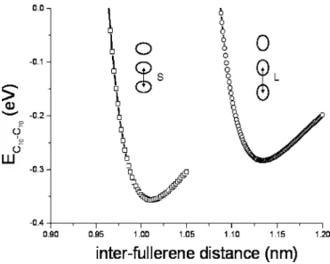
for small distances, the repulsive part of the Lennard-Jones interaction is important and the molecules minimize their looking parts by rotating one with respect to the other, while attraction makes them parallel for larger distances. Whatever it is, the small differences in energy as a function ofmean that at room temperature molecules will more or less present all orientations in共300 K⯝0.026 eVⰇ0.005 eV兲. The en-ergy of interaction Efull-fullis shown as a function of L in Fig.
7. The minimum in energy gives the equilibrium configura-tion for a chain of molecules. For a chain of lying molecules, the equilibrium distance is L = 1.13 nm and for a chain of standing molecules, equilibrium corresponds to L = 1.01 nm and= 0. Energy per molecule of a chain of standing mol-ecules 共−0.36 eV兲 is smaller than that of a chain of lying molecules共−0.26 eV兲. Molecules in an isolated chain would thus take the standing orientation with respect to the chain axis rather than the lying one.
B. The tube-fullerene energy
The interaction energy between a C70 molecule inside a nanotube and the nanotube is drawn in Fig.8for a molecule in lying or in standing orientation. In the calculations, mol-ecule position was fixed on the central axis of the nanotube.
The interaction energy Etube-fullis named entrance potential in Ref. 13 or reaction energy for fullerene encapsulation in Refs.10and11. It can be defined by the following process:
C70+ nanotube→ C70@nanotube + Etube-full.
One deduces from Fig.8 that the minimum nanotube di-ameter for the insertion of a C70molecule, corresponding to
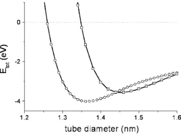
Etube-full= 0, is about 1.26 nm. It can also be shown in Fig.8 that a molecule adopts the lying orientation in thin tubes and the standing one in thick tubes共a similar result is obtained in Ref. 11; it is a rather obvious result which can be deduced from simple steric hindrance considerations兲. For a single molecule inside the tube, the critical tube diameter between lying and standing orientations, corresponding to the inter-section between the energy curves of lying and standing mol-ecules, is found to be⌽LS⯝1.45 nm.
FIG. 7. Interaction between two C70molecules as a function of the distance L between their centers. Open squares correspond to parallel standing molecules and open circles to lying molecules.
FIG. 8. Energy of a C70molecule inside a nanotube as a
func-tion of the tube diameter共open circle, lying molecule; open square, standing one兲.
C. The total energy
The total energy per molecule in the peapod, which is the sum of the fullerene-fullerene and fullerene-tube energies, is shown in Fig.9. The interaction energy between two mol-ecules being lower in the standing case than in the lying case, the critical diameter⌽LS between lying and standing orientations is slightly displaced towards lower values with respect to the one determined above for isolated molecules. It is found to be⌽LS= 1.44 nm.
D. Discussion
Let us first discuss the results of our calculation with re-spect to experiments. The critical diameter⌽LS between ly-ing and standly-ing orientations is determined to be 1.44 nm from our calculations and 1.42± 0.02 nm from x-ray diffrac-tion experiments. Good agreement is thus obtained here. It should however be noticed that the agreement is not as good as far as interfullerene distances are concerned: calculations give L = 1.01 and 1.13 nm for standing and lying molecules, respectively, while experiments give L = 0.98 and 1.1 nm. Calculations lead to a slight overestimate of the inter-fullerene distances. As for the value of the entrance diameter ⌽ent, different values are deduced from calculations and ex-periments: the calculated diameter is 1.26 nm while the di-ameter deduced from x-ray measurements is 1.32± 0.02 nm. But one should underline that the energetic model does not take into account the temperature while fullerene encapsula-tion is carried out at about 600 ° C. Differences in entropy between fullerenes inside and outside the tubes should thus be taken into account. The entropy being higher outside the nanotube than inside the tube, insertion will not occur for the diameter corresponding to Etube,full= 0 but for larger diam-eters 共Etube,full= −T⌬S where T is the temperature of encap-sulation and⌬S is the difference in entropy between a free and an encapsulated molecule兲. This may explain why the value of ⌽ent deduced from energy calculations is smaller than the measured one.
We now compare in TablesIII andIV calculations per-formed within the scope of a van der Waals 共vdW兲 model
with total-energy electronic-structure共TEES兲 calculations in Ref.11共from TableIand Fig.2in this paper兲. Interfullerene
distances 共Table III兲 appear to be better evaluated using
TEES calculations 共with calculated values of 0.99 and 1.11 nm, as compared to the experimental ones of about 0.98 and 1.1 nm兲. Interaction energies obtained from the two types of calculations in TableIVare very different. Such an amazing discrepancy can also be noticed for calculations relative to C60 peapods, where for a 共10,10兲 tube, Girifalco and co-workers report an entrance energy of −3.25 eV共van der Waals calculations兲 to be compared to −0.4 eV for Yoon and co-workers 共ab initio structure optimization techniques兲.29Dispersion forces are difficult to calculate and comparison with experiments is essential. For van der Waals interactions, the critical diameter ⌽LS between lying and standing chains, corresponding to the intersection between the energy curves Etot for lying and standing molecules, is estimated to about 1.44 nm. For TEES calculations, one can deduce from TableIVthat it is located above 1.44 nm 共be-tween 1.44 nm and 1.51 nm兲. The van der Waals model thus gives a value of⌽LScloser to experiment共where it is deter-mined to be of about 1.42 nm兲 than TEES calculations.
In summary, on the basis of the present data concerning C70peapods, van der Waals calculations appear more reliable as far as the orientation of the molecules is concerned but the distances between molecules are better estimated using TEES calculations. One may also note that Khlobystov and co-workers briefly present density-functional based tight-binding calculations in Ref. 8 and that they obtained the lying orientation in共10,10兲 nanotubes 共⌽T= 1.37 nm兲 and the standing one in共11,11兲 nanotubes 共⌽T= 1.51 nm兲, in agree-ment with our results and those of Okada and co-workers.
At the end of this paper, some of the hypotheses made should be discussed in more details. First, we only consid-ered the standing and lying orientations, while intermediate orientations may also have been considered. Second, the molecules were assumed to be located along the central axis of the nanotube while off-center positions have been pre-dicted to occur when tube diameters are sufficiently large, leading to more complex arrangements than linear chains, such as zigzag chains.20,26 We have thus developed further calculations within the van der Waals model. First, we mini-mized Etube,fullas a function of the inclination of the mol-ecule long axis with respect to the nanotube axis. It follows that between 1.40 and 1.44 nm in tube diameter, a single molecule inside the nanotube progressively reorients from the lying to the standing orientation共varies from 0 to 90°兲. Moreover, we found that if molecules are allowed to shift off the nanotube axis and if second-neighbor interaction between molecules are taken into account, zigzag chains form above
FIG. 9. Total energy per molecule in the lying case 共open circles兲 and in the standing case 共open squares,=0兲.
TABLE III. Distances between standing and lying C70
mol-ecules from total-energy electronic-structure 共TEES兲 and van der Waals共vdW兲 calculations.
TEES vdW
Standing 0.99 nm 1.01 nm
⌽T= 1.5 nm. Accordingly, in molecular dynamic calculations performed by Troche and co-workers,26linear and zigzag C
70 packings are found in共11,11兲 tubes 共⌽T= 1.496 nm兲 and in 共12,12兲 tubes 共⌽T= 1.632 nm兲, respectively. As discussed for C60chains by Hodak and Girifalco,27fullerene packing could even be more complicated because the perfect zigzag struc-ture is probably not stable at room temperastruc-ture, being stabi-lized via the rather weak second-neighbor interactions. It was noticed in Sec. IV B that agreement between simulations— made under the assumption that peapods contain only stand-ing and lystand-ing molecules located on the tube axis—and ex-periments is correct but that it should be improved. Further developments of the present work should thus take into ac-count off-centering and inclined configurations of the C70 molecules. However, we do believe that the present ap-proach, although simplistic, allowed us to get the main fea-tures of the C70 peapod structure, that is the formation of linear chain of lying molecules below about 1.42 nm in nanotube diameter and of chains of standing molecules above.
VI. CONCLUSION
In conclusion, we have presented x-ray diffraction experi-ments performed on powders of C70 peapods and on refer-ence single-walled nanotubes. The distribution of nanotube diameters in the samples can be described with a Gaussian function centered at 1.42 nm with FWHM= 0.2 nm. We have developed a formalism to simulate diffraction patterns taking into account molecule orientations. It is shown that careful analysis of the diffraction patterns allows two critical tube diameters ⌽enc and ⌽LS to be determined. Below ⌽enc = 1.32± 0.02 nm, nanotubes are empty: encapsulation of C70 molecules is thermodynamically unfavorable. Between⌽enc
and⌽LS= 1.42± 0.02 nm, molecules adopt the lying orienta-tion, with their long axis parallel to the tube axis. The peri-odicity of linear chains of lying molecules is about 1.1 nm. Above ⌽LS= 1.42± 0.02 nm, molecules adopt the standing configuration, with their long axis perpendicular to that of the tube. Interfullerene distance is then ⯝0.98 nm. Energy calculations have been performed within the scope of a van der Waals model. Calculated intermolecular distances are slightly overestimated but it is found that the calculated tube diameter⌽LS being the diameter frontier between lying and standing orientations is correct. The simple van der Waals model appears here reliable as far as the orientation of the molecules is concerned.
ACKNOWLEDGMENTS
Vincent Pichot, Stéphan Rouzière, and Pierre-Antoine Al-bouy are acknowledged for their help in some of the x-ray scattering experiments. The authors are grateful to Philippe Lambin, Jean-Christophe Charlier, and Julien Cambedouzou for helpful discussions and to the French Programme ANR-PNANO for funding. Teams involved in this work belong to the International Research Consortium entitled “Science and Applications of the Nanotubes”共CNRS GdR 2756兲.
APPENDIX: ENERGY CALCULATIONS
Calculation of interaction energies have been done nu-merically. Let us report in some details the formula used.
The fullerene-fullerene energy in Eq.共18兲 corresponds to
a double integration over the linear elements dl1,= R⬜d
and dl2,= R⬜d, on circlesandon the two molecules 关see Fig.4共a兲for the definition of R⬜and兴. No simplifica-tion is made in the standing case, while in the lying case, defining=−, one easily shows that Eq.共18兲 gives
Efull-full= 2
兺
,=0 8 nnR⬜R⬜冕
0 2冉
− A 关R⬜2 + R⬜2 +共L +−兲2− 2R⬜R⬜cos共兲兴3 + B 关R⬜2 + R⬜2 +共L +−兲2− 2R⬜R⬜cos共兲兴6冊
d.TABLE IV. Etube,fulland Etotfrom total-energy electronic structure共TEES兲 and van der Waals 共vdW兲 calculations for standing and lying
C70molecules in nanotubes.
⌽T
Standing case Lying case
Etube,full共eV兲 Etot共eV兲 Etube,full共eV兲 Etot共eV兲
TEES vdW TEES vdW TEES vdW TEES vdW
1.35 −0.47 0.09 −0.75 −0.27 −1.85 −3.70 −2.09 −3.96
1.43 −1.30 −3.14 −1.58 −3.5 −1.60 −3.37 −1.84 −3.63
For the tube-fullerene energy in Eq.共19兲, integration must
now be performed over three coordinates: the anglefor a point M on circle of the molecule, an angleTand the Z coordinatefor a point P on the nanotube. One obtains an expression of the form
MP2= F共⌽T,R⬜,,兲 + 共−兲2 for a lying molecule and
MP2= G共⌽T,R⬜,,兲 + 关− R⬜sin共兲兴2 for a standing molecule. The variablevaries from −⬁ to ⬁. Integration over can be performed analytically using the recurrence formula
冕
dz 共a + z2兲n+1= z 2na共a + z2兲n+ 2n − 1 2na冕
dz 共a + z2兲n. One obtains Etube-full= ⌽TT 2兺
=0 4 R⬜n⬘
冕
0 2 d ⫻冕
0 2 d冉
− 3A 8f5/2+ 63B 256f11/2冊
,where f = F for a lying molecule and G for a standing one;
n0
⬘
= n0and n⬘
= 2nfor= 1 – 4. Numerical integration is per-formed over the two variables and.*Corresponding author. Electronic address: launois@lps.u-psud.fr
1B. W. Smith, M. Monthioux, and D. E. Luzzi, Nature共London兲
396, 323共1998兲.
2M. Monthioux, Carbon 40, 1809共2002兲.
3Carbon Nanotubes: Synthesis, Structure, Properties and
Applica-tions, edited by M. Dresselhaus, G. Dresselhaus, and Ph. Avouris
共Springer-Verlag, Berlin, 2001兲.
4Understanding Carbon Nanotubes, From Basics to Applications,
edited by A. Loiseau, P. Launois, P. Petit, S. Roche, and J.-P. Salvetat Springer Series: Lecture Notes in Physics, Vol. 677 共Springer, New York, 2006兲.
5D. J. Hornbaker, S. J. Kahng, S. Misra, B. W. Smith, A. T.
Johnson, E. T. Mele, D. E. Luzzi, and A. Yazdani, Science 295, 828共2002兲.
6P. Jaroenapibal, S. B. Chikkannanavar, D. E. Luzzi, and S. Evoy,
J. Appl. Phys. 98, 044301共2005兲.
7K. Hirahara, S. Bandow, K. Suenaga, H. Kato, T. Okazaki, H.
Shinohara, and S. Iijima, Phys. Rev. B 64, 115420共2001兲.
8A. N. Khlobystov, R. Scipioni, D. Nguyen-Manh, D. A. Britz, D.
G. Pettifor, G. A. D. Briggs, S. G. Lyapin, A. Ardavan, and R. J. Nicholas, Appl. Phys. Lett. 84, 792共2004兲.
9L. Guan, H. Li, Z. Shi, L. You, and Z. Gu, Solid State Commun.
133, 333共2005兲.
10M. Otani, S. Okada, and A. Oshiyama, Phys. Rev. B 68, 125424
共2003兲.
11S. Okada, M. Otani, and A. Oshiyama, New J. Phys. 5, 122
共2003兲.
12H. Ulbricht, G. Moos, and T. Hertel, Phys. Rev. Lett. 90, 095501
共2003兲.
13L. A. Girifalco, M. Hodak, and R. S. Lee, Phys. Rev. B 62, 13104
共2000兲.
14C. Journet, W. K. Maser, P. Bernier, A. Loiseau, M. Lamy de la
Chapelle, S. Lefrant, P. Deniard, R. Lee, and J. E. Fisher, Nature 共London兲 388, 756 共1997兲.
15S. Rols, R. Almairac, L. Henrard, E. Anglaret, and J. L. Sauvajol,
Eur. Phys. J. B 10, 263共1999兲.
16A. Thess, R. Lee, P. Nikolaev, H. Dai, P. Petit, J. Robert, C. Xu,
Y. Lee, S. Kim, A. G. Rinzler, D. T. Colbert, G. E. Scuseria, D. Tomnek, J. E. Fischer, and R. E. Smalley, Science 273, 483 共1996兲.
17Y. Maniwa, Y. Kumazawa, Y. Saito, H. Tou, H. Kataura, H. Ishii,
S. Suzuki, Y. Achiba, A. Fujiwara, and H. Suematsu, Jpn. J. Appl. Phys., Part 2 38, L668共1999兲.
18J. Cambedouzou, V. Pichot, S. Rols, P. Launois, P. Petit, R.
Kle-ment, H. Kataura, and R. Almairac, Eur. Phys. J. B 42, 31 共2004兲.
19Y. Maniwa, H. Kataura, M. Abe, A. Fujiwara, R. Fujiwara, H.
Kira, H. Tou, S. Suzuki, Y. Achiba, E. Nishibori, M. Takata, M. Sakata, and H. Suematsu, J. Phys. Soc. Jpn. 72, 45共2003兲.
20M. Hodak and L. A. Girifalco, Phys. Rev. B 67, 075419共2003兲. 21K. H. Michel, B. Verberck, and A. V. Nikolaev, Phys. Rev. Lett.
95, 185506共2005兲.
22K. H. Michel, B. Verberck, and A. V. Nikolaev, Eur. Phys. J. B
48, 113共2005兲.
23S. Ravy, P. Launois, R. Moret, and J.-P. Pouget, Z. Kristallogr.
220, 1059共2005兲.
24W. Zhou, K. I. Winey, J. E. Fischer, T. V. Sreekumar, S. Kumar,
and H. Kataura, Appl. Phys. Lett. 84, 2172共2004兲.
25M. Hodak and L. A. Girifalco, Chem. Phys. Lett. 363, 93共2002兲. 26K. S. Troche, V. R. Coluci, S. F. Braga, D. D. Chinellato, F. Sato,
S. B. Legoas, R. Rurali, and D. S. Galvao, Nano Lett. 5, 349 共2005兲.
27M. Hodak and L. A. Girifalco, Phys. Rev. B 68, 085405共2003兲. 28P. Launois, S. Ravy, and R. Moret, Int. J. Mod. Phys. B 13, 253
共1999兲.
29M. Yoon, S. Berber, and D. Tománek, Phys. Rev. B 71, 155406