Development of Rapidly Deployable Structures for Military Applications:
A System Based Approach to Command Post Facilities
by
Jakob A Hopping
PROFFERED TO THE DEPARTMENT OF MECHANICAL ENGINEERING IN ORDER TO SATISFY THE REQUIREMENTS FOR THE DEGREE OF
BACHELOR OF SCIENCE IN MECHANICAL ENGINEERING AT THE
MASSACHUSETTS INSTITUTE OF TECHNOLOGY
-MASSACHUSETTS INSTTUTE OF TECHNOLOGY
JUNE 2006
AUG 0 2 2006 © 2006 Jakob A Hopping. All rights reserved. LIBRARIES
The author hereby grants to MIT permission to reproduce and to distribute publicly paper and electronic copies of this thesis document in whole or in part in any medium
now known or hereafter created. Any requests for permission to use portions of such theses must be made to the student author.
Signature of Author:
q7
Department of Mechanical Engineering May 12, 2006
Certified by:
Accepted by:
Zhong You Visiting Scientist, Oxford University Department of Engineering Science
and John A. Ochsendorf &.=11 o,' Professor, Department of Architecture Thesis Supervisors
: l. ·
John H. Lienhard V Professor of Mechanical Engineering Chairman, Undergraduate Thesis Committee
1
Development of Rapidly Deployable Structures for Military Applications: A System Based Approach to Command Post Facilities
by
Jakob A Hopping
Proffered to the Department of Mechanical Engineering on May 12, 2006 in order to satisfy the requirements for the Degree of Bachelor of Science in Mechanical
Engineering
Abstract
Today's battlespace is the most dynamic in recorded history. Accompanying other military improvements, Command and Control (C2) technology has also been
modernized. In spite of advances in technology, it currently takes six times as long to deploy a Command Post (CP) as it did eight years ago. This decline in performance results in poor communication with forward units due to an increased distance between the units and the CP. This performance decline also increases the danger posed to command centers by enemy elements in the rear.
Although each component of a modern CP functions well, CP structures are slow to deploy because many of the components of the command structure are developed separately to fulfill specific functions. Separately, these components are quick and innovative. Combined, they are cumbersome and labor intensive to assemble. The command structure must be viewed as a system that requires an encompassing solution. This thesis presents a rapidly deployable CP structure developed using a system based approach. The functional elements of a Command Post were analyzed and a
comprehensive structure was designed to enhance the speed of CP establishment. Also, the appropriate background theory for structural and safety analysis was developed and applied to the resulting design.
The proposed design, termed the Automated Command Post (ACP), is capable of
establishing Command and Control in a mere fifteen minutes from start to finish; this is a 92% improvement over existing CP structures. In order to maximize the potential
usefulness of the physical space within the ACP, the recommended ACP layout was constructed by modifying existing command post layouts using network theory. The ACP is an air-supported structure that requires a nominal pressure of only 0.036 psi to withstand up to 75 mph winds. Also, the ACP inflation system has an estimated fuel cost of only '/2 a gallon per day to maintain this pressure.
Thesis Supervisor: Zhong You
Title: Visiting Scientist, Oxford University Department of Engineering Science
and
Thesis Supervisor: John A. Ochsendorf
Biographical Note
Jakob A Hopping is a candidate for a Bachelor of Science in Mechanical Engineering with a focus in Entrepreneurial Management and a Minor in Political Science at MIT. Jakob's work experience includes over eight years with the United States Marine Corps Reserve, two years as a personal trainer and health fitness instructor, and many years in grass-based dairy farm management.
While serving in the Marine Corps Reserve, Jakob was activated in support of Operation Enduring Freedom from December 2001 - December 2002. He started his Marine Corps career inl998 as an Infantry Rifleman before becoming a Ground Operations Specialist in 2004, and then later becoming an Intelligence Specialist in 2005. Jakob has worked with a regimental sized Combat Operations Center (COC) for seven years. During these seven years, Jakob has seen COC technology change from paper maps and thumbtacks to digitized media displays and network communications. Additionally, he has personally used many of the Command Post (CP) systems that were used and are currently being used by the Marine Corps.
Acknowledgements
I would like to thank Dave Custer for his invaluable input during the early stages of this thesis, and Cam Brensinger for providing hope that the desired functionality of the Automated Command Post could be accomplished. Also, this thesis would not be complete without the help of my two thesis advisors Zhong You and John Ochsendorf who provided guidance and asked more questions than I can answer. Lastly, I thank my wife, Amy, for being so supportive through the long nights of work and my son, Kaleb, for trying to understand why Papa had to spend so much time in the library room.
Table of Contents
Abstract . . . ... 3
Biographical Note ... 4
Acknow ledgem ents ... ... 4
Table of Contents ... 5
1.0 Introduction ...7
1.1a Problem Statem ent Historical Background ... 8
1.1 Problem Statement ... 10
2.0 Existing Tent Structures and Methods of Design . ... 11
2.01 Current Rapid Deployment Structural Designs ... 11
2.01a Pole Supported Tents ... 11
2.01b Tensioned Fabric Tents ... 13
2.01c Air Bubble Tents ... 13
2.01d Air Beam Tents ... 14
2.02 Demonstrated Military Need ... 15
2.03 Current Military Command Structures ... 16
2.03a Deployable Rapid Assembly Shelter (DRASH) ... 17
2.03b Base-X ... 18
2.03c Modular Command Post (MCP) ... 19
2.04 M ethods of Design ... 19 2.04a Interviews ... 20 2.04b Model Building ... 20 2.04c Research ... 20 3.0 Background Theory ... 21 3.01 Fabric Stress ... 21
3.01a Internal Air Pressure ... 21
3.01b Self-Weight ... 24
3.01c Snow Loading ... 25
3.01d Wind Loading ... 27
3.01e Equivalent Stresses ... 29
3.02 Buckling of Camouflage Canopy Support ... 29
3.03 Air Leakage Rate ... 32
3.04 Energy Cost of Structural Support ... 34
3.05 Camouflage and Thermal Radiation Blocking ... 38
3.06 Anchorage Requirements ... 42
4.0 Design of the Automated Command Post ... 45
4.01 Preliminary Ideas ... 45
4.01a M echanical versus Air Supported ... 46
4.02 Choice of Shape ... 57 4.02a M odularity ... 57 4.02b Stress Concentrations ... 58 4.02c Usable space ... 61 4.03 Anchorage Design ... 62 4.04 Access Design ... 64 4.05 Inflation System ... 65
4.06 Thermal Shielding & Cam ouflage ... 66
4.06a Ribbed Sides & Insulative Interior Panels ... 68
4.06b Integrated Camouflage Netting ... 70
4.07 Designing Usage Enhancement ... 73
4.07a Organizational Structure of a Command Post ... 74
4.07b Networks and Communication ... 76
4.07c Physical Space Enhancements ... 79
5.0 Discussion . ... 83
5.01 Safety. ... 83
5.02 Theory ... 83
5.03 Design, Analysis, & Mechanics Modeling ... 85
6.0 Conclusion ... 86
1.0 Introduction
Current military Command Post (CP) structures do not adequately meet the requirements imposed by an increasingly dynamic battlefield. Battlefield maneuver occurs at a faster pace than ever before in history, and this faster advance is accompanied by a porous battle edge. Many antagonistic elements are deliberately bypassed by a porous front push and left behind the main maneuvering attack elements. This leaves certain enemy units and groups intact and behind the main advance with the capability of a rear based strike on Command and Control (C2) facilities.
The fast pace of the battlefield and the existence of enemy contingents to the rear of the main advance pressure Combat Operations Centers (COCs) to be capable of rapid deployment and redeployment. As the time required to establish a COC goes up, the distance over which communications with forward units occurs also increases. Increased distances stretch the limits of current communications capabilities and place forward elements which need Fire Support Control (FSC) and commanding guidance from the
COC at a higher risk of communications failure. The inability of a COC to redeploy also increases the hazards posed to it by rear enemy elements. The longer it takes to
dismantle a COC and transport it to another location the greater potential exist for damage to be inflicted on C2 capabilities by rear operating enemy elements.
The CP facilities in use currently are sluggish and require a large amount of time to deploy and redeploy. This cumbersome and labor intensive nature of the command structures today does not meet the functional requirements imposed upon it by the elements of fast-paced maneuver and enemy contingent forces operating behind the Forward Edge of the Battle Area (FEBA).
The purpose of this thesis is to develop an Automated Command Post (ACP) which provides a deployable system tailored specifically to the needs of tactical military
command. This thesis focuses on identifying the reason current deployable structures are inadequate, and then takes advantage of the author's extensive CP experience in
The ACP is tailored specifically to meet the identified system requirements of military tactical command centers. This thesis takes a global approach in the tailoring process. First, some historical deployable structures are introduced. Then the problem addressed by this thesis is firmly articulated. Next, the overall background of tent-like structures, with a special focus on those currently used in the military today, is developed. After the background, the methods of design are discussed and then followed by a development of the background theory necessary to properly analyze the suggested ACP design. Once the background theory has been developed, the design itself is described element by element with each decision explained. Areas not fully explored by this thesis and
suggestions for further research are then discussed after the design is fully explained, and, finally, the end design is summarized in a concluding section.
1.1a Problem Statement Historical Background
Historically, many societies have developed and used simple, mobile structures with multi-use characteristics and quick assembly. These structures range from the large and intricate nomadic pavilions of early Arab societies in the African desert to the small and efficient design used by the Mongols - the Yurt. Overall, most of these structures are tent-like and serve the purpose of housing people or goods in a variety of situations. The Mongols used the Yurt for housing people and goods when invading territory. Similarly, the Native American plains tribes used a Teepee when migrating to different hunting and crop growing grounds.
Much like the societies of old, today's military has many uses for rapid deployment structures. Common applications of such structures range from the housing of military personnel and equipment to providing locations that facilitate military C2. Current military tactics require that C2 centers use complex computer aids located in large tents that are numerous and collocated with each other. This configuration of tents and
equipment is called a Combat Operations Center (COC). Although current COC tents are easier and faster to set up than permanent structures of the same size, they are
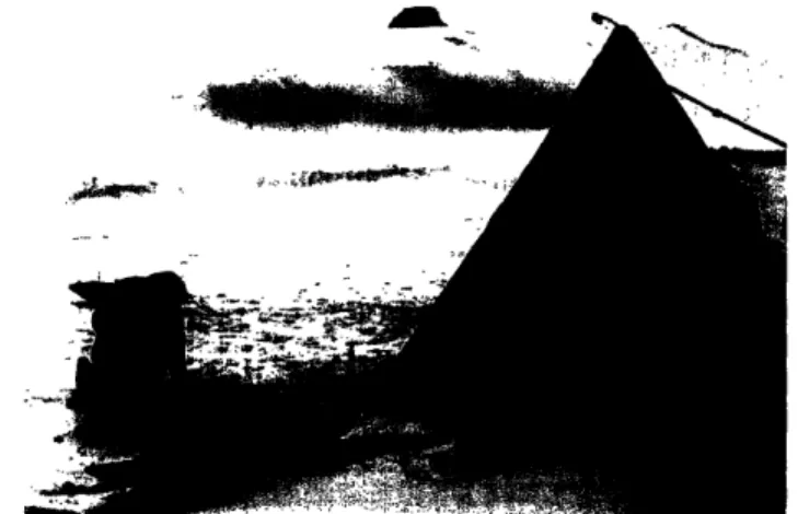
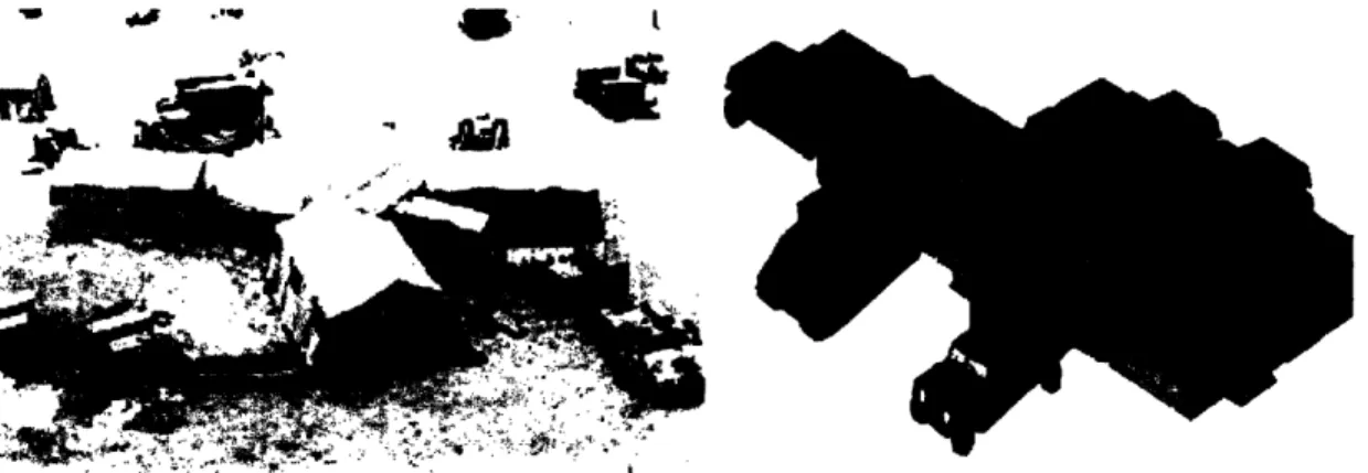
cumbersome and difficult to use. Some COC configurations use so many tents that they are jokingly referred to as "tent cities" (see figure 1). This is problematic. As the
number of tents and equipment utilized increases, the time required to establish the structures also increases.
I I
a
Figure 1: "Tent-City" composed of a NATO Command and Control (C2) facility with many connected and collocated tents. Notice the camouflage netting over the exterior of the structures.l
Time is the single most important factor in setting up command structures. Increased infantry mobility through the use of Infantry Fighting Vehicles (IFVs) and the
employment of indirect contact tactics has resulted in a front line which moves faster than ever before in history. Indirect contact tactics are methods of avoiding long engagements with the main enemy force in an established defense. Rather than engaging the bulk of the enemy directly, infantrymen use the speed of IFVs to punch through the enemy location and establish a credible threat to the rear of the opponent's location.
Because the majority of tactical radios transmit over relatively short distances, 10-50 kilometers, fast approach warfare tactics decrease the amount of time that command centers can communicate with the forward elements under their command without the
AFSOUTH, Images (2003 September 02). Photos of NATO Support to Turkey. May 1 2006, NATO OTAN: <http://www.afsouth.nato.int/operations/NATOTurkey/photos%20patriots/DSC00603.jpg>
establishment of radio relay and retransmission sites. Because of this, it is vital for a CP to be capable of setting up with minimal manpower and time.
1.1 Problem Statement
The United States military, in particular the United States Marine Corps, has a
demonstrated need for a rapidly deployable, tactical, command structure system. The functional requirements of this system are:
1) The system must be transportable via existing military vehicles with overall dimensions that do not exceed the capacity of existing trailers and other towed equipment.
2) The system set-up time must be 30 minutes or less (time begins at the initiation of equipment unload and ends when the facility can assume command of the
battlefield).
3) The system must provide environmental control that will protect computing systems from detrimental heat, cold, and humidity.
4) The system must have enough space to facilitate coordination of information and intelligence among work groups.
5) The structure must minimize infrared emissions and be compatible with existing camouflaging techniques.
This thesis outlines the main categories of current tent structures and explains the specific requirements of a CP in more detail. Current CP structures are examined according to satisfaction of the above identified functional requirements. Proposed improvements are developed, and the ACP is then designed specifically to meet the developed
2.0 Existing Tent Structures and Methods of Design
The background of rapid deployment structural designs is presented here; then closely followed by a more detailed explanation of the military need. A critique of the existing military command structures then follows, and, lastly, the methods of ACP design are presented.
2.01 Current Rapid Deployment Structural Designs
Older tent structures tend to be of a pole and fabric design. In these structures, poles provide the structural integrity of the tent, and fabric provides protection from
environmental factors such as: wind, rain, and sun. Examples of such older structures are the Yurt and the Teepee. Similar mechanical designs are used more today such as the
Scott tent. Some tent designs that are not as old as the Yurt and Teepee have made use of the tent fabric as a structural member in tension. The lower density of structural poles needed for support, provides structural stability at lower weight. Examples of such
designs are the Civil War four-man tent, the Army General Purpose (GP) tent, and many of the tents provided by recreational companies for large outdoor events. More recently, tents that utilize pressure inside a completely sealed fabric for structural support have
been developed. The pressure gradient between the atmospheric pressure and the inside structure pressure creates a net pressure and resultant upward force on the tent. Examples of such structures are sports facility "bubbles" and carnival "fun tents." Other modem tents use pressurized air beams for structural support. In those designs the air beams perform a mechanical function similar to the poles in a pole supported tent. Examples of such tents are tents made with NEMO's air supported technology.2
2.01a Pole Supported Tents
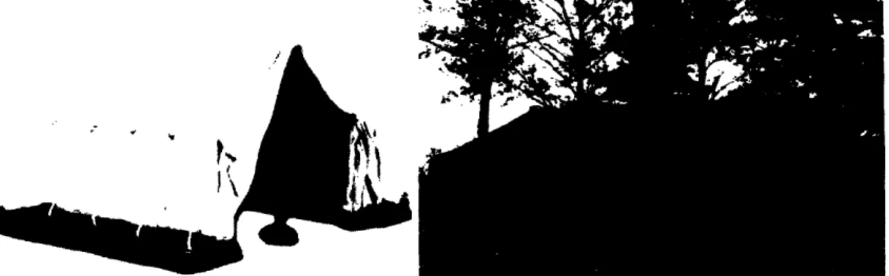
Both the Yurt and the Teepee use a wooden frame for structural support with a fabric covering for wind and weather proofing (see figure 2). The Yurt is a structure that when formed it resembles a traditional building. It has a great weight to occupancy ratio of
2 "Air Supported Technology." NEMO Equipment. 14 Dec. 2005
about 50 Kg per occupant. However, the Yurt lacks the flexibility of deployment enjoyed by the Teepee. A Teepee is easier to transport than the Yurt and is more tent-like in function. The Teepee is unique among tent-like structures. In addition to its mobility and weather resistance, the Teepee has a ventilation capability that allows a fire inside of the tent. The structural design of the Teepee influenced many modem pole structures. One such structure is the well known Scott tent. The Scott tent, pictured in figure 3,
Figure 2: Mongolian Yurt (left) and American Teepee (right). The Yurt can be easily carried by livestock and weighs about 250 Kg making it about 50 Kg per occupant. The American Teepee has a similar weight ratio and transportability. Additionally, the Teepee is a more traditional tent design with unique ventilation capabilities.3 4'5
Figure 3: The Antarctic expeditionary Scott tent. This shelter uses hollow aluminum poles and provides excellent shelter at a minimal weight.6
3 Yurt Living. 16 Dec. 2005 <www.yurtliving.com/>.
4 "School Reports: South Dakota Fact and Information." Kids' Page. South Dakota Govenor's Office. 16
Dec. 2005 <http://www.state.sd.us/govemor/Main/kids/SR.htm>.
5 Melin, Nicholas O'Brien. "Application of Bennett Mechanisms to Long-Span Shelters." P.hD Thesis: Magdalen College - Univeristy of Oxford. Trinity Term 2004.
6 "TIGER in Antrartica." Trans-iron Galactic Element Recorder. 13 Nov. 2001. NASA. 16 Dec. 2005
<http://tiger.gsfc.nasa.gov/tigerl 1 13.html>. Wi
was designed by Captain Robert Scott for use in the Antarctic. The Scott tent was one of the first modem deployable tents, and it utilizes lightweight aluminum poles for structural
support. It is clear that the structural design of the Scott tent has many similarities to the Native American Teepee.
2.01b Tensioned Fabric Tents
The Civil war four man tent living quarters is an early example of a tent that utilized tensioned fabric for structural support. One of the benefits of this type of design is its scalability. The four man tent used during the Civil War is a small scale version of the General Purpose (GP) tent commonly used by the military today, see figure 4. The only limit in the scaling of a tensioned fabric structure is the weight of the fabric itself.
Advances in fabric strength per weight result in an increase in the size of tent that can be made with tensioned fabric. Many tents provided by recreational companies for outdoor events are tensioned fabric tents similar in design to the Civil War four man tent living quarters and the GP tent.
Figure 4: The Civil War tent used to house four fighting men (left), and the General Purpose (GP) tent used currently for many military applications (right). Modem outdoor party tents are of a similar design to these two tents as well.7'8
2.01c Air Bubble Tents
Air bubble tents are air supported structures that utilize a pressure difference between atmospheric pressure and that created inside a fabric bubble by a blower system for
7 "William Britain Civil War Tent." Collectable Toys Online. Trinkets to Treasures. 16 Dec. 2005
<http://www.trinketstotreasures.com/wb7 I.htm>.
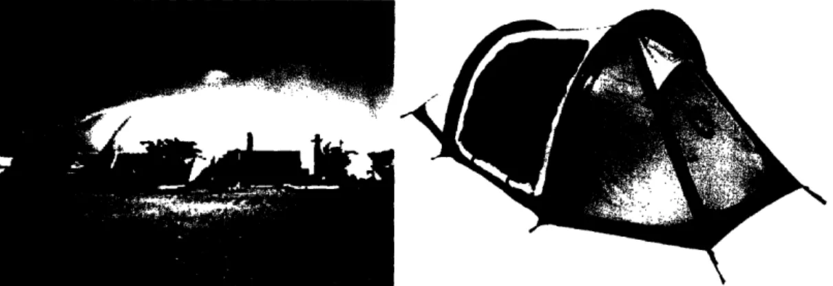
structural stability (figure 5). Because there is no internal frame, the shape of the fabric and the stresses caused by the internal pressure defines the overall shape of the erected structure. This type of system is commonly used to create rather large structures for a relatively low cost. Because of this air bubble tents are often used to create large outdoor athletic facilities such as covered tennis courts or swimming pools at a relatively low cost.
2.01d Air Beam Tents
The most recent innovation in tent structural design is the implementation of an air beam for structural support (see figure 5). Air beams provide a great degree of transport flexibility as well as a reduction in weight from metallic frames. The general structural concepts of an air beam tent are similar to a pole supported structure; however, due to the complete freedom of movement during the setup process a there is great flexibility in designing the packaging and shape of these structures.
Figure 5: Air bubble tennis facility (left) and the air beam supported Sako from NEMO Equipment (right). The flexibility in shape and design of air supported structures cannot be matched by traditional frame or tensioned fabric structures.9
9 "Air Supported Structures." Architectural Fabrics. Shelter-Rite. 16 Dec. 2005 <http://www.architecturalfabrics.com/airsupported.html>.
10 "Tent Features." NEMO Equipment. 16 Dec. 2005 <http://www.nemoequipment.com/products_tents.asp>.
2.02 Demonstrated Military Need
Military command centers need to be capable of displacing (from one location to another) and setting up quickly. Easy deployment is necessary in order to maintain
communication with forward units, escape enemy counterassaults to the rear of the forward line, and provide the commander with the use of high tech intelligence multi-media, unit tracking programs, and the Common Operational Picture (COP). The resources provided by the command center are vital components to the tactical decision making process; however, these components are of little use if the structure that houses them is incapable of keeping up with the operational tempo of today's fast paced battlefield.
Tactical C2 in today's battlefield takes advantage of a plethora of high-tech audio and visual media tools which aid in conveying information to the tactical commander. Without this information, appropriate decisions cannot be made in the timely manner necessary for saving lives and accomplishing assigned missions. In spite of the
advancements in information handling technology, the structures, designed to provide an environment conductive to information coordination, have become increasingly difficult to set-up, disassemble, transport, and re-locate. This cumbersomeness is due to the increased size of camouflage netting utilized, the greater complexity of tent mechanics, and the large wiring infrastructure that must be created each time the command facility is set-up.
Set-up times for a regimental sized command structure have gone from thirty minutes (starting of equipment offload to operational time) eight years ago to three or more hours today. This time increase is accentuated by the increased speed at which the battlefield front moves with modem US warfighting tactics. Fast moving front line forces quickly reach the limit of their ground based communications. The communications equipment currently employed has a line of sight range of 10-50 km prior to emplacement of relay and retransmission sites. This short range can place great strain on a tactical command center's ability to control the battlefield if set-up times are in excess of an hour.
Additionally, the adoption of a porous front line in current tactics makes the chance of a hostile encounter with a small but completely intact enemy unit more likely than it was in World War I and II. During World War I and II, a more marked and impermeable
forward battle edge was the preferred tactic, and engagements with intact enemy units to the rear of the battle front were rare. During the Iraq offensive, many completely intact enemy units were purposefully passed by the forward edge of troops in order to secure key positions beyond certain Iraqi troop holdings. Although this did not result in many attacks on CPs left open in the rear, CPs were undamaged because the Iraqi units lacked the discipline to carry out operations without communications from higher headquarters. Thus, these Iraqi units which were left unscathed by the main thrust of coalition forces disbanded rather than utilizing their advantageous rear position to attack. In future conflicts, this favorable lack of unit discipline and cohesiveness in enemy troops should not be assumed nor anticipated. Tactical command centers must be prepared to not only provide the security necessary for such possible threats but to also relocate rapidly to more secure locations while maintaining command of the battle space to which they are assigned.
The main reason command structures today require so much time to set up is that each component used in the command post is designed separately with little thought as to how long it might take to create a complete CP. In particular, little has been done to combine the internal wiring, CP tent, and external camouflage netting - the three most time consuming components of the setup process. In the review of current command structures, the critique most often levied is this lack of compatibility with the required uses of the tents which results in slower deployment times.
2.03 Current Military Command Structures
Some military command post tent structures currently used are similar in design to those used during the Civil War. Civil War field command tents used a canvas fabric
suspended in tension between wood poles and guy-wires staked into the ground. Today the commonly used General Purpose (GP) Tent in use by the US military is of a similar design. Other tents, such as the Modular Command Post Tent (MCP), use a modular
aluminum frame for structural support. The fabric in these soft-walled tents is usually made of polyester and it plays no part in structural stability." However, the design of these tents is similar to the design of the Mongolian Yurt. Other than fabric and material advancements, not much has changed in the design of many of the CP tents used today.
2.03a Deployable Rapid Assembly Shelter (DRASH)
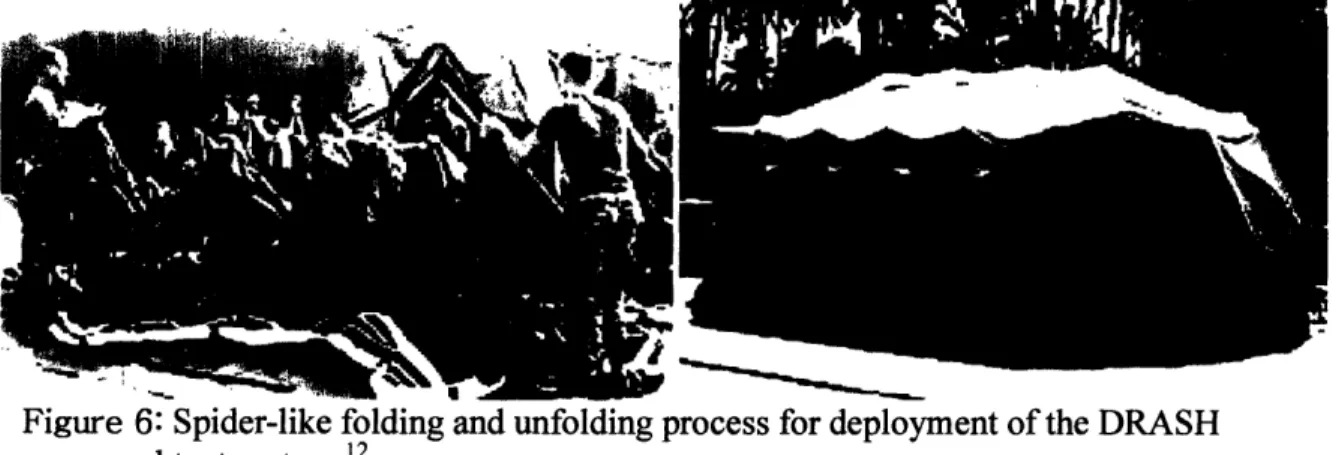
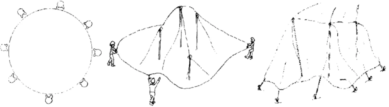
The DRASH tent is commonly used by the Marine Corps for C2. A few years ago it was the preferred tent and it was difficult to receive funding approval from Headquarters Marine Corps for a different tent system. A pole supported frame tent structure, the DRASH tent folds and unfolds in a spider-like manner for setup and takedown. Figure 6
shows this spider-like action. The DRASH tent is a complex design that is prone to inadvertent stresses during the deployment and re-deployment phases. These
unintentional stresses will, over time, result in plastic deformation of the scissor-like structural support members. These deformations eventually cause a blockage during tent deployment which results in an overloading of the deformed support and subsequent fracture. Replacing the broken support can take an hour or longer which makes repair of this tent a liability. In addition to this shortcoming, the DRASH tent does not incorporate other system requirements such as camouflage netting, power wiring, and intranet wiring necessary to a functional CP. Installing each of these other items separately increases the setup time when using the DRASH system regardless of how fast the actual tent can be set-up.
Figure 6: Spider-like folding and unfolding process for deployment of the DRASH command tent system. 2
" "Modular Command Post Tent (MCP)." Outdoor Venture Corportation. 14 Dec. 2005 <http://www.outdoorventure.com/tent_systems/mcp.html>.
2.03b Base-X
Like the DRASH system, the Base-X is a spider-like folding and unfolding pole
supported design. Figure 7 schematically shows the process by which the Base-X tent is deployed, and figure 8 shows an example command post setup with several Base-X tent structures arranged in a modular configuration.
Figure 7: The sequential unfolding and setup process for the Base-X tent.'3
The Base-X tent is much like the DRASH tent in design and the shortcomings are similar. Repair is a lengthy process, and breakage can be easily caused by accidental stresses during the deployment phase. The tent system does not integrate enough of the
components commonly used within the tent to effectively reduce the time for setup even if the tent setup time is minimal.
-
*
AMFigure 8: Base-X command post configuration with attached environmental control elements (left). Modular Command Post (MCP) tents configured in a typical setup with attached support vehicles (right).'14 15
3 "Expedition Shelters." Base-X. 16 Dec. 2005 <http://www.base-x.com/military/index.html>.
14 "Command and Control." Base-X. 16 Dec. 2005 <http://www.base-x.com/military/command.html>. '5 "Modular Command Post Tent (MCP)." Outdoor Venture Corportation. 14 Dec. 2005
<http://www.outdoorventure.com/tent_systems/mcp.html>.
C`
2.03c Modular Command Post (MCP)
The MCP is an older, conservative CP design. An example of a COC setup using the Modular Command Post is portrayed in figure 8. Although the MCP does not
incorporate any system features such as climate control like the Base-X or DRASH designs, it has a relatively lightweight packed configuration and takes up minimal space. Its simplicity makes it the most robust design currently used as a Command Post
structure, and it requires the fewest people to set-up. In spite of these advantages, the Modular Command Post still has moving joints that are prone to failure. The MCP also has very long setup times due to the lack of integration with other vital aspects to a CP setup such as: power, heating & cooling, intranet, and camouflage netting.
2.04 Methods of Design
The Automated Command Post has several distinctive parts to its design process. The first part articulated is the simple mechanical theory to explain the behavior of the planned design. This background theory is developed in the next section and formulas
listed there are utilized through this thesis for desired calculations. Following the theoretical model is a short record of the actual decision process with each of the
individual elements and the decisions involved in the element design process described in detail. As each piece and consideration of the design is portrayed, the appropriate
theoretical analysis is also used. The organizational nature of the structure is examined, and the architectural properties are closely modeled. The modeled architectural
properties are specifically engineered to enhance the ability of the structure to meet the coordination and information flow requirements of a Command Post. Following the description of the Automated Command Post components is a discussion of the portions of the analysis which are not fully explored and suggestions for further improvements are made. Finally, conclusions regarding the Automated Command Post and the final
2.04a Interviews
As the design process unfolded, informal and formal interviews with potential users and with peers were used to help guide the design process. Many of these interviews resulted in rapid progress and change in the design of the ACP. The results from these interviews have been vital to furthering this research, and each person positively contributed to the project as a whole.
2.04b Model Building
A scale model of the proposed ACP was constructed to aid in visualization of the mechanisms employed and to gain an intuitive feel for the air supported mechanics in general. This understanding was coupled with mechanics modeling and theory building to aid in providing for the safe engineering of the structure. All the appropriate
precautions for fire, rupture, doorway fault, proper anchorage, and local buckling were taken in the final product.
2.04c Research
Many mechanical concepts and difficulties presented in the design of the Automated Command Post (ACP) are explored in detail by existing publications. Research into such published details served to form a library of knowledge that proved useful when
designing the ACP. The publications used range from academic tomes to theses on large scale deployable structures. These publications are used throughout the following sections to aid in the application of certain principles to the design of the Automated Command Post. In the following pages, the results of the above described methods are explained with the background theory, design, discussion, and conclusion.
3.0 Background Theory
The Automated Command Post has many functional mechanical elements which require theoretical formulas modeling their behavior in order to effectively design each element. Not every design element is modeled in this background theory section; however, many of them are modeled. The main elements which are examined in detail are: the fabric stresses, the leakage rate of the air within the tent at optimal pressure, the subsequent energy cost of structural support, the force loading and buckling mode of the camouflage netting supports, the infrared radiation emissions from the structure, and the necessary anchoring force. The background formulas for each of these main components of analysis are presented here; however, the application of each model to the ACP is presented with calculations in the design section of this thesis.
3.01 Fabric Stress
The fabric stresses can come from four sources: internal air pressure, self-weight, snow loading, and wind loading. Rain loading is also possible; however, this can be
approximated as an increase in self-weight in all but the most extreme of cases. Each of these cases is outlined below with a theoretical model presented for the case in question.
3.01a Internal Air Pressure
The general stress formula for revolved air supported thin shells presented below closely follows the derivation of Douglas Wright of the University of Western Australia,
Department of Mechanical and Materials Engineering.16 First, the desired shape is rotated about the upright axis thereby forming a thin shell of uniform thickness (t) and then stresses resulting from an internal pressure (p) are modeled. This rotated
axisymetrical shape is shown in figure 9. If we consider an element located at the point A (defined by a, 6(p, 60) in the meridian (r-z) plane (shown in figure 9), then the
components of the pressure and stress in the direction of the outward normal due to the
16 Wright, Douglas. Thin Shells of Revolution - Heads. May 01 2005, Notes on Design and Analysis of
internal gauge pressure p and the meridional stress (a,) and circumferential stress (ao) are:
pressure:p-A = p(r-8)-rqr.4,
meridional stress: -2-.o.(t-r-)-sin( ) and circumferential stress:-2.o- (tr.)-sin (o )
11 2-sin(qo)
Pling
r
-9 I I I I I I
Figure 9: The conceptual rotation of the meridian about the z-axis (upper left). The rightmost figure shows the element at point A where the local surface normal cuts the z-axis at the point B, and AB is defined as the radius r. The center of curvature lies at C on the normal, and AC is the instantaneous radius of curvature of the meridian r,. The bottom left figure shows the vertical equilibrium in the dished area above the hoop
circle.17
If we note that r = r0o sin (qp) and take the limits while holding the element 6A in
equilibrium, we arrive at the membrane equation: CI+O:=_°° P p(4)
r r0 t
and considering the equilibrium in the dish area above the hoop circle shown in figure 9 we can show that:
2r
rp = 2--rt-a.-sin(e
) .
(5)
17 Wright, Douglas. Thin Shells of Revolution - Heads. May 01 2005, Notes on Design and Analysis of
Machine Elements: <http://www.mech.uwa.edu.au/DANotes/pressVessels/shells/shells.html>
(1)
(2)
(3)
.z
Combining equations 4 and 5 we can express the membrane stress components in terms of the rotated geometry, re and r,:
for meridional stress = ( 2P.)r0 (6)
and for circumferential stress .+a2 0o= -
f.
(7)The automated command post is composed of an elliptical end cap combined with a cylindrical bottom element. Thus, the solutions to the stress equations 6 and 7 as well as the ones derived below for self-weight, snow, and wind loading that we are concerned with are those that apply to the particular geometry of a cylinder and an ellipsoid. In the case of the cylinder:
r =- and r-- oo (8)
Plugging into equations 6 and 7 for the meridional and circumferential stress in the cylindrical portion the following is obtained:
D c0 = p.-D and (9) 2t 0 0 =-0 (10)
In the case of the ellipsoid, an ellipse of semi-major and semi-minor axes a, b, is formed with an eccentricity defined as follows:
(bX (11)
Then, defining u to be a function of r such that: u = f(r) we find that, for the ellipse, u is the following:
U= 2 - where <u<l. (12)
i a
Plugging into equations 6 and 7 we obtain the following stress relationships for the ellipsoid top portion of the ACP:
=
(.-u3
and
6+= P.-jU;(13)
re = a ). u and 0 = . -2 . (14)
3.01b Self-Weight
The self-weight, snow loading, and wind loading formulation presented here closely follows the material set forth by Frei Otto in Tensile Structures. 18 The fabric weight is expressed as a weight per unit surface area. This formula is usually expressed as
W = pt-g. (15)
Since p is the density of the material, g is the gravitational acceleration constant, and t is the thickness of the material; W is the weight per unit surface area. The component of the gravitational force acting in the direction of the membrane can then be found by discovering the tangential component trigonometrically. This results in the following identities, which are displayed in figure 10: F, = W sin 0, F0= 0, Fr = -W cos 0.
Figure 10: The dl membrane; W is the
total gravitational force. 19
In the previous identities, F, is the force in the meridional direction, F0is the force in the
circumferential direction (this is perpendicular to the gravitational force W and thus equal to zero), and Fr is the force in the radial direction or perpendicular to the fabric.
The general formula of axisymetrical self-weight loading is the following:
gravity = t 2
f
R.s (X)RO().sin(X) dx, and (16)t-w.%sin 0
-W-Ro-cos R0
°0gravity= - ravity, (17)
18 Otto, Frei and Trostel, Rudolf. Tensile Structures. Cambridge, MA: The MIT Press, 1973. Pg: 185-194
and the integration in formula 6 goes from X = 0 to X = 0.
Plugging in the R, and Re for an ellipsoid from equations 13-14 and integrating we arrive at the following simplified gravitational stresses:
-W a.u3.0
.
=
,and
(18)
g-ellipsoid t 3 b (TO _ (·· .Cos (19) g-ellipsoid t b 3(19) 3.01c Snow LoadingSnow loading can take two forms; it can be a top accumulation or a standard distribution per unit area of the membrane. Both forms are presented here for examination. First we will solve the standard distribution per unit area of the membrane. This first form has two solutions depending upon the angle po0. The first case is for snow acting upon the entire membrane. It goes as follows:2 0
Osnow - 2 |J R(X) R0(x)sin(x)-cos2(X) dX, and (20)
t'R0-sin 0 -s-R-cos34 Ro
O0snow = - a 0 now for 4< 0<_ (21)
t N 2
In the above equation, s is the vertical snow load per unit surface area of the membrane and the remaining variables are as previously defined in formula and geometric depictions. The second formula for the standard distribution condition is for when the
snow only acts upon the upper part of the membrane. The equation is: 21
( )RR ()(22)2 R()nsnow =
-%
*0snow Snow, fo r 2 - ° (23)
20 Otto, Frei and Trostel, Rudolf. Tensile Structures. Cambridge, MA: The MIT Press, 1973. Pg: 187-188
The above is the representation of the standard "distribution according to DIN 1055, p.5, by vertical load per unit area."22 S is equal to 75 kg/m2. The drawing on the right in figure 11 depicts the snow load on the inflated shell and possible membrane shape changes due to a distributed snow load.
, S
lx----i Figure 11: Loading and possible local buckling form for an accumulated snow load on an axisymetrical membrane (left), and the loading and possible deformation form for a
standard distribution snow load (right).23
The accumulated snow load only affects the area that the snow has accumulated on. This measure assumes that the snow will not build up with a uniform distribution as was assumed above. The left schematic in figure 11 depicts this type of snow load with a possible deformation pattern. The below formulas mathematically describe this behavior. The first set is outlined here:2 3
a4snowpartial = s 2 (x)-R().()sin(x)cos 2() dX, and (24)
t-R-sin 4 0
-s-Ro.cos 3 R0
0snowpartial = Qsnowpartial for < <. 1.
And the second set is here:2 3
= asnowpartial(l) Re(+l).sin(l) and (26)
4Cnowpartial 2
t. (+).sin2q
a0snowpartial = R snowpartial for 2 l. (27)
These equations readily provide solutions for the desired axisymetrical snow loading.
22 Otto, Frei and Trostel, Rudolf. Tensile Structures. Cambridge, MA: The MIT Press, 1973. pg: 187 23 Otto, Frei and Trostel, Rudolf. Tensile Structures. Cambridge, MA: The MIT Press, 1973. pg: 188
I
II(
3.01d Wind Loading
Wind loading is unique from the previous fabric stresses; because, it cannot be
realistically modeled as an axisymetrical load. From Tensile Structures by Frei Otto et al the summarized derivation is as follows. First, we assume that the loading of the
membrane due to wind is modeled as pressure acting along the surface normal called n, such that the following is true:
P = PO = 0, and Pr = -n. (28)
Then for the sake of modeling stresses in a static state we will assume that the wind is blowing from the negative x-axis toward the positive x-axis with a wind pressure described by constants no and nl as follows:
n = no + n-Isin(+).cos(0). (29)
The constant no is the axisymetrical wind loading factor and the constant nl is non-symmetric in the meridional plane and non-symmetric in the circumferential plane. The corresponding sectional loads are then described, and by plugging into the previously derived anti-symmetrical loading formula the following relationship for the meridional and circumferential stresses, respectively, is found:
a wind fos(n ) and (30)
aO = -n i-Rosin(+)-cos(0) R . (31)
0 ~~wind' qb-wind
Where the meridional factor is found by: nl
fqn = R 2 .)i2 3( (4(X) - R0(x)-cos(x))-R-R 0 sin3 (X) dx. (32)
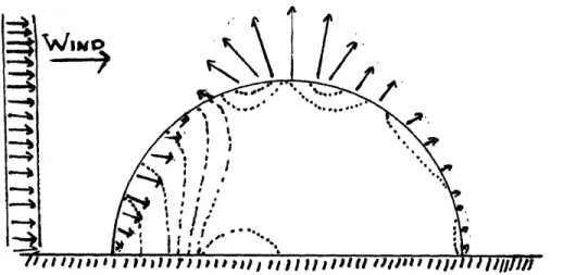
Calculating the actual wind pressure to input into the above formulation is not an easy task. The pressure on a structure due to wind varies from a plunging pressure on the front (windward) face of a structure to a grabbing suction on the top and rear (leeward)
surfaces.24 The magnitude and direction of these pressures as characteristically seen in a hemispherical shell exposed to winds is shown in figure 12.
24 Wagner, Craig H.. "Determining Wind Loads On Buildings." Architectural Testing 01 May 2006
.
I t 11111
Figure 12: The magnitude and direction of forces on the membrane due to a constant wind pressure. The surface lines depict lines of constant stress.25 26
Generally, a good estimate of the pressure due to wind can be found through the
2 Vair
Bernoulli's equation for streamline flow: Pwind = 2 P air 27 This simplification equates the pressure to the kinetic energy of the wind due to bulk velocity. Using this simplification based upon the stopped wind pressure, we find that a "fresh gale blowing at ... 48mph will exert a pressure of 296 Pascals [or 0.3% atm] on a building." 28
Elaborating on these further and applying multiplying factors to adjust for the variations exhibited with greater height, and shape we can express the above formula as: 2 9
2 2
Vair Vair Patm
Pwind = 2 airFshapeFght .Fshape Fheight (33)
2 ' aiFshpeFheight p 2 Rat Tair
where the wind pressure is in terms of the velocity of the wind (Vair), the density of the air (Pair), and two scale factors (Fshape and Fheight). Fshape is on the order of 0-1 and compensates for the aerodynamic qualities of the building shape, and Fheight is on the order of 0-3 and it incorporates the increased gust and velocity potentials encountered at
25 Dietz, A. E., and Proffitt, R. B. and Chabot, R.S. and Moak, E. L.. Wind Tunnel Test and Analyses for
Ground-Mounted Air- Supported Structures.Technical Report 70-7-GP. Natick, MA: U.S. Army Natick
Laboratory, 1969. pg: 256-257
26
Zingoni, Alphose. Shell Structures in Civil and Mechanical Engineering. Oxford: Thomas Telford, 1997.
pg 115
7 Ochshorn, J. "Wind." Building Structures and Construction. Cornell University. 01 May 2006 <http://instructl .cit.cornell.edu/courses/arch264/cuhk/courseNotes/wind/wind.html>.
28 "Wind Pressure & Flow Around Buildings." The Vent-Axia Ventilation Handbook. 01 May 2006
<http://www. vent-axia.com/sharing/windflow.asp>.
29 "Wind speed and wind pressure." KNMI Hydra Project. 16 Jan 2006. Royal Netherlands Meteorological
Institute. <http://www.knmi.nl/samenw/hydra/faq/press.html>.
greater heights.3 0 For the case of the automated command post, we will use an assumed
Fshape of 0.8 and Fheight of 1.5. This formula gives the wind pressure in Pascal based upon the shape and height of the structure as well as the design wind velocity.
3.01e Equivalent Stresses
This general form of the stresses within air supported membranes will be applied to the particular shape of the ACP and equivalent stresses determined. The equivalent stress can be determined using the Mises equivalent stress equation:
°miseseq = 2i.( - c0)2 + (0 - ar)2+ (a (34)
Since the fabric shell is thin relative to the size of the radius of the enclosure (r/t >10), the fabric lacks the ability to carry shear stresses; thus, or is negligible. The only stresses "felt" by the fabric are biaxial in nature resulting from the tensile application of o, and ao. Therefore, the equivalent stress can be rewritten in the following form:
amises-eq = (, - 0)2 + ()2+ ()2 (35)
3.02 Buckling of Camouflage Canopy Support
The camouflage canopy is traditionally supported by hollow Aluminum tubular sections.
Because the slenderness ratio - for this structure is about 350, where L' is the
rgyr
effective length of the column and rgyr is the radius of gyration, failure of the canopy supports will take the form of buckling. The radius of gyration is given by the square root of the second moment of inertia divided by the cross sectional area which
is rgr = -, where the area moment of inertia is IA = r - ri) and the cross
2 2
sectional area is A = ro2-7 - rj i .. In the previous equations, Ro is the outside radius and
Ri is the inside radius of the hollow cylindrical cross section. The effective length L' is
30Ochshom, J. "Wind Data." Building Structures and Construction. Cornell University. 01 May 2006 <http://instruct I .cit.comell.edu/courses/arch264/cuhk/courseNotes/wind/windData.html>.
given by the total length of the supporting pole times the effective length constant, k, (L' = L - k). In the case of the camouflage canopy, the effective length constant k is equal to one. This is because, as shown in figure 13, the lack of mechanical connection with the ground and the flexible nature of the canopy holding onto the supporting pole from above are both best modeled as pin joints. Euler's effective length constant for a pinned-pinned column is k = 1.
jIanopy 7
'IN N
Figure 13: The poles supporting the camouflage netting are best modeled as a pinned-pinned long column.
The critical buckling stress of the canopy supports is found via the following equation:
2
ng -E.IA
abuckling (36)
where E is equal to the Young's modulus of elasticity for the material and the other values are as previously defined.
In spite of the relatively simple calculation for the buckling stress of the camouflage support poles, calculating the actual forces from the camouflage netting is not so simple. Usually, numerical methods are necessary to calculate the stresses within a tensioned membrane such as the camouflage netting. However, for our purposes some simplifying assumptions give a reasonable calculation of loading force for the support poles.
The stresses on the outer netting poles will not exceed those already endured by existing camouflage netting poles; thus, no additional calculation is necessary for those pole emplacements. This is primarily because the relative density of poles surrounding each ACP module is high. However, the center pole will span a larger distance with a higher weight factor than the current poles are exposed to. Therefore, the center pole should be
r
stronger than the current poles, and an estimate of the potential stresses should be given. If we imagine that the maximum possible stress on the center netting support for each module of the command post is created when the other poles are not installed, then the
following diagram in figure 14 depicts the maximum loading on the center pole.
,
Le
Figure 14: Simplified pole loading by camouflage netting.
In the above figure the force downward on the pole is given by:
F = T-sin0, (37)
with T equal to the tension in the camouflage netting, and 0 is as defined in figure 14. The minimum force (F) that can be experienced is found by this:
Fmin = Wcn, (38)
where the weight of the camouflage netting (Wcn) is equal to the following equation: Mass (cn)
Wcn = A rea g'Area
In equation 39, Ac is the area of the camouflage netting which is multiplied by the mass of the netting per unit area and the gravitational acceleration constant (g). The resultant
stress on the support pole can be found by this equation:
with Ac as found above (A r - ri (40)
Ac
Applying a safety factor of three, the design stress is less than or equal to one-third the calculated buckling stress:
1
Note that this is a rudimentary calculation of center pole stress that should be verified via numerical analysis and with a finalized shape prior to manufacture. However, this model provides an excellent first approximation of the design criteria.
3.03 Air Leakage Rate
For the Automated Command Post, the rate of air leakage due to pressurization is
dependant upon the internal gauge pressure and the size of the openings though which the air can leak. Ramskill has published many closed form solutions to this particular type of formulation, and the equations presented below are simplifications of these derivations.3 1
The calculation of the ACP leakage rate is simpler than other leakage problems. This simplification of derivation is due to the establishment of the assumption of constant pressure. At constant pressure the rate of air flow out of an orifice of a particular size
will not vary with time; thus, the instantaneous rate of air leakage is equal to the average rate of leakage so long as the inflation system is capable of maintaining close to constant pressure in spite of said leak. There are two main types of leak flow rate formulations: choked and non-choked.3 2 The Automated Command Post is non-choked because of its
low gauge pressure.
If we consider that the gauge pressure required for the Automated Command Post is very small (i.e. on the order of 0.3% of atmospheric pressure), then we can assume that the rate of air leakage through a hole in the ACP fabric will be sub-sonic in nature. Since the pressure differential is small, the velocity of the air flow is not restricted by the maximum speed of information flow through air and no supersonic restrictions are imposed on the system. Theoretically, if the ratio of internal absolute pressure over external absolute pressure is less than [(k + 1) / 2] k /(k - 1), where k is equal to the specific heat ratio of air, then the resultant flow is non-choked.3 3 The specific heat ratio of air (k) is equal to the
31 Ramskill, P.K., "Discharge Rate Calculation Methods for Use In Plant Safety Assessments", Safety and
Reliability Directory, 1986, United Kingdom Atomic Energy Authority 32 "Accidental release source terms." Wikipedia. 2006. 01 May 2006 <http://en.wikipedia.org/wiki/Accidental_release_source_terms>.
33 Beychok, Milton R.. "Calculating Accidental Release Flow Rates." Fundamentals Of Stack Gas Dispersion. 01 May 2006 <http://www.air-dispersion.com/feature2.html>.
specific heat of air at constant pressure (cp) divided by the specific heat of air at constant volume (cv). These equations are presented below for clarity:
=2i= 716 and Cair Rair
= 2 8 7 c ir vaj (42)
kg.K vair kg.K
Rair is the specific gas constant for air and the other variables are as defined above. The flow ratio which determines whether the escaping velocity is choked or non-choked is given by the following:
C P a ir k = Or and (43) CV air k k k- I FlOWratio = 2 ) (44)
Leaks resulting from a ratio of absolute pressure inside the ACP over the external absolute pressure which is less that equation 44 will be non-choked. As stated above, above the ultra-low pressure in the ACP does indeed yield this result. This is empirically shown with the following:
Patm = 101323a and PACP = 0.03si + Patm (45)
PACP
Thus the ratio of pressures is equal to = 1.002 (46)
Patm
which is much lower than the flow ratio obtained from equation 44 above. The flow ratio for air is Flowratio = 1.893, and, since the ratio of absolute pressure within the Automated Command Post over the exterior atmospheric pressure is less than this ratio, the observed velocity of escaping air from inside the ACP through a hole is non-choked.
This observation is shown by the following inequality:
k PACP (k+I k-I
Patm < ' (47)
In the case of non-choked air flow through leaks, the following relationship describes the behavior of the leakage rate (Lr):
I 2 (k+ 1)
Rr'T k 1 Patm (Patm k (48)
The leakage rate in equation 48 is expressed in terms of the previously defined terms and the area of the hole through which the air is leaking (Atear) times a discharge coefficient (Cd). Under the square root, T is equal to the temperature of the discharged air in absolute degrees Kelvin (°K). The discharge coefficient is shape dependent and non-dimensional. Generally, a Cd value of 0.72 is accepted as a reasonable value for most thin wall pressurized container leaks.34 However, laboratory measurements show that Cd does vary considerably especially in cases with low values of Reynolds number.3 5 Research on the determination of the discharge coefficient of a thin-walled orifice published in the Journal of Tribology shows many empirical results with Cd values averaging around 0.836 In spite of this, 0.72 is accepted as a reasonable estimate of the discharge coefficient for this particular application.
3.04 Energy Cost of Structural Support
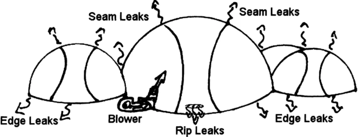
Since the Automated Command Post is air supported, there is an inherent energy cost associated with maintaining the required air pressure. The replacement of the volume of air lost due to the leakage rate calculated in section 3.03 is accomplished through work being done on the ACP by a blower system. Figure 15 graphically illustrates this described behavior. The structurally maintaining phenomenon illustrated below is, by definition, an open system with the following relationships by the first and second laws of thermodynamics respectively:
dEcv dQ dW dmin v dmout
i t h +2 2Ldt + +g g-z and (49)
d dt dt i
[
dt 2in ut
·3-out
dS I1 dQ dSgen (dmin m o.( dout (50
dt T(dt) dt dt dt
in out
34
Beychok, Milton. "Source Terms for Accidental Discharge Flow Rates." Online Chemical Engineering Information. 01 May 2006 <http://www.cheresources.com/discharge.shtml>.
35 "Orifice, Nozzle and Venturi Flow Rate Meters." Engineering Tool Box. 01 May 2006
<http://www.engineeringtoolbox.com/orifice-nozzle-venturi-d_590.html>.
Ed
Rip Leaks
Figure 15: Maintaining the structural support of the Automated Command Post requires automatically replacing escaping air via a blower.
Formula 49 states that time rate of energy change in the control volume is equal to the time rate of heat flow into the system minus the time rate of work conducted out of the system plus the net time rate of change of stored energy via mass transfer. The net time rate of change of stored energy via mass transfer in the system is equal to the flow of mass with summed energy modes (m-h = enthalpy, m v2/2 = kinetic energy, and m-gz gravitational potential energy) in minus the flow of mass with summed energy modes out. Likewise, formula 50 states that the rate of accumulation of entropy in the control volume is equal to the net entropy transfer into the control volume plus the rate of entropy
generation in material plus the net rate of entropy addition via mass driven entropy inflows and outflows.
The command post itself can be assumed to be in steady state; however, this assumption is only useful to show that the input energy is equal to the output energy. In the steady state case, the above general analytical approach to the dynamic support of the
Automated Command Post can be further simplified by assuming that the rate of mass flow in is equal to the rate of mass flow out, the change in gravitational potential energy is negligible, and the change in kinetic energy is negligible. These and other assumptions are presented briefly below:
In steady state, the mass entering the command post is equal to the mass leaving the command post, or, in other words, the time rate of change of mass within the control volume (the ACP) is equal to zero.
dmcv (dmin dmout
dtv m dm t therefore Amin = Amout; (51)
dt dt dt
Likewise the volume of the command post is constant under a constant pressure. Thus the rate of work performed on the mass of air already within the command post is equal to zero.
VACP = Constant and PACP = Constant therefore PdV= 0. (52) Because the change in gravitational potential energy and the change in kinetic energy is negligible we can exclude them from the formula.
(Avin)2 (Avout)2 and gin = g'Zout. (53)
2 2
The density of the air is given by the following formula:
P
Pair= , (54)
RairT
and the time rate of mass leaving the command post can be found by the following:
dm
m = LrPaii * (55)
dt
The enthalpy of the air is given by the below:
h = cp airT . (56)
Combining formulas 51-56 with formula 49 we arrive at the following simplification:
PACP dQout Patm dQin
_____ __ - _ Br-, (57)
Rair dt Rair dt
Lr is as defined in equation 48, and Qout is described in equation 66. Br is the blower rate, and the other variables are as previously defined. This formulation could prove useful in determining the total energy cost including that of environmental control. However, it is useful to find the total work required by the blower system to support the ACP per unit time in an isothermal state using the setup described in figure 16.
If we model the blower system as a mass that provides a constant pressure at a variable volumetric rate equal to the volumetric flow exiting the Automated Command Post via leaks (Lr) as found above in equation 48, then the following formula describes the rate of work placed into the system by the blower:
Wrate = PACP (58)
t
where the rate change in volume (AV/t) is equal to Lr and PACP is the gauge pressure of the Automated Command Post.
I
J/tm -,APISTON
Figure 16: Simplified model of the work required to maintain constant pressure in the Automated Command Post given a leakage rate (Lr). The rate of work is equal to the rate of leakage times the given gauge pressure inside the command post.
The rate of fuel use by the blower system is then calculated by dividing the work rate from equation 58 by the available energy output of the blower system. The available energy output of the blower system is found by multiplying the efficiency (9r) of the blower times the available energy density of the fuel that the blower uses to perform work. Therefore the basic energy cost per unit time of static structural support for the ACP is found by:
Fuelrate = ( W (59)
Edensity
This energy cost calculation is in volume of fuel per unit time; it is useful to calculate this number as gallons of fuel per minute.
3.05 Camouflage and Thermal Radiation Blocking
There is no rigorous mathematical model or methodology for determining the degree to which objects can be sighted via the visible light spectrum; however, reduction of thermal
signatures employs some basic concepts of heat transfer by conduction, convection, and radiation. The more qualitative aspects of visible light recognition reduction are
presented in the design section of this thesis under integrated camouflage netting. The background theory presented here deals solely with the reduction of thermal radiation off of the surface of the command post structure.
The steady state flow of heat from inside a structure to the outside environment or vice versa is dependent upon the temperature difference between the two environments, the boundary material's resistance to heat flow, and the surface area over which this transfer of heat occurs. If the material resistance to heat flow goes down or if the surface area over which the transfer occurs goes up, then the steady state flow of heat goes up. Likewise, larger temperature gradients produce larger heat flows between the two environments. The surface area of the Automated Command Post is complex because it incorporates a spheroid top attached to a cylindrical bottom. This yields an unwieldy formula for heat flux through the wall of the ACP. Because the ACP is very large and the height of the cylindrical portion is rather close to the large radius of the oblate ellipsoid top of the ACP a spherical approximation of surface area can be made which is close to the actual surface area. Figure 17 graphically shows a hypothetical module for the ACP with dimensions a, b, and h.
!
a
Figure 17: The dimensional determination of a single ACP module. Representative dimensions would be a = 10', b = 7.5', and h = 6'.
The eccentricity of the ellipsoid top is given by:
Ecc = I - , and (60)
the surface area of this ellipsoid top is given by:3 7
ECC ECC (61)
A spheroid = 7. 2b + 1 (61)
Likewise the surface area of the cylindrical portion of the ACP is calculated using:
Acylinder = 2.a.h. (62)
Therefore, the total surface area of the ACP is found via:
Atotal = 2Aspheroid + Acylinder. (63)
If we model the ACP as a sphere with a radius given by:
(h + b + a) (64)
rsphere 2
then the estimated surface area is found by '/2 the surface area of a sphere with said radius
rsphere. This area is given by the following:
Aest = 2- ( +a) 2 (65)
This spherical approximation has an error factor of 5-10% for the range of geometries considered for the ACP.
The rate of heat flow out of this spherical model is given by this equation:
47trkeff(TAcP - Te) , (66)
qr= 1
L(rsphere - t) rsphere
where keff is the effective resistance of to the flow of heat, TACP is the temperature of the air inside the command post, Te is the temperature of the air outside the command post, and t is the overall thickness of the command post wall. The various resistances to heat flow in the command post wall are defined by the following three equations:3 8
37 "Ellipsoid." Wikipedia. 01 May 2006 <http://en.wikipedia.org/wiki/Ellipsoid>.
38 Incropera, Frank P, and DeWitt, David P. Fundementals of Heat and Mass Transfer. 5th. Danvers, MA:
lclld (67)
Rcond 4.7t.keff (rsphere - t) rsphere
and (68)
Rcvin= hin.4.7r.(rsphere -t)6
Rc°V out hout·4 7. rsphere (69)
The variables above are as previously defined with hin and hout being the effective coefficient of convection on the inside and outside walls of the ACP, respectively. The total resistance to heat flow in the command post is found by summing the resistances from equations 67 to 69. This total resistance is shown in the below equation in accordance with the principle of thermal resistances in series as shown in the graphical depiction of a potential ACP wall with representative temperature distributions (figure
18):
Rtotal = Rcov in +Rcon + Rcovout (70
g
:Layer
Rcond R0ou0,
~~ W M~ T.1hu
Figure 18: The composite nature of the ACP wall as designed (left), the equivalent resistance diagram (center) with the conductive resistances lumped, and the expected temperature profile through the ACP wall (right). Note that the temperature profile is drawn with the assumption of a positive heat transfer into the environment; however, this relationship is also true for a negative heat transfer into the environment. In the later case, the temperature is increasing downward.
Finally, the rate of heat transfer from equation 66 can be related to the total resistance via this equation:
5.
!-(TAC - Te)
qr (71)
Rtotal
Using equation 70 and 71, it can be shown that the temperature of the outside wall is found with:
T
wa = TACP t - qr(Rwalut), (72)
where Rwallout is equal to the total resistance minus the outside convective resistance
(Rtotal - Rcovout) or to the resistance of the inside convection plus the wall conduction (Rcovin + Rcon).
Thermal imaging resolves the difference in radiative heat transfer that two objects have to the outer environment. This observed difference via thermal imaging is dependent upon a variation of surface temperatures. If the surface temperature of two rocks is very similar or if the difference is smaller than most other temperature differences nearby, then thermal imaging will not be able to resolve the two separate rocks. Likewise, if the temperature of the outside layer of the command post (as found in equation 72) is similar to the temperature of the air surrounding the command post, thermal imaging will have difficulty detecting the presence of the command post exterior wall. This relationship can be seen from the general equation for radiative heat transfer below: 39
qrad = hrA('Tfar - Tsur). (73)
In equation 73, A is the surface area of the object emitting the heat, Tfar is the temperature of the environment far away from the surface of the emitting object, Tsur is the surface temperature of the emitting object and hr is defined by this equation:
hr = 6-o(Tfar + Tsur)(Tfar + Tsur2), (74)
where is the emissivity of the emitting object's surface, and o is the Stefan-Boltzmann constant (c = 5.67 x 10O8 W/m2 -K4). By equation 74, if the surface temperature of the ACP is close to the surface temperature of the surrounding air, there will be little
discernable difference in the resulting thermal radiation from each. Thus, the Automated Command Post surface will be camouflaged from thermal imaging. This does not mean, however, that high temperature internal elements will not be discernable.
39 Incropera, Frank P, and DeWitt, David P. Fundementals of Heat and Mass Transfer. 5th. Danvers, MA: John Wiley & Sons, 2002.