HAL Id: cea-02183846
https://hal-cea.archives-ouvertes.fr/cea-02183846
Submitted on 15 Jul 2019
HAL is a multi-disciplinary open access
archive for the deposit and dissemination of
sci-entific research documents, whether they are
pub-lished or not. The documents may come from
teaching and research institutions in France or
abroad, or from public or private research centers.
L’archive ouverte pluridisciplinaire HAL, est
destinée au dépôt et à la diffusion de documents
scientifiques de niveau recherche, publiés ou non,
émanant des établissements d’enseignement et de
recherche français ou étrangers, des laboratoires
publics ou privés.
A Flexible Physical Layer for LPWA Applications
Valérian Mannoni, Vincent Berg, Francois Dehmas, Dominique Noguet
To cite this version:
Valérian Mannoni, Vincent Berg, Francois Dehmas, Dominique Noguet. A Flexible Physical Layer
for LPWA Applications. International Conference on Cognitive Radio Oriented Wireless Networks
(CROWNCOM ) 2017, Sep 2017, Lisbon, Portugal. �cea-02183846�
A Flexible Physical Layer for LPWA Applications
Valérian Mannoni, Vincent Berg, François Dehmas and Dominique Noguet
CEA, LETI, MINATEC Campus, F-38054 Grenoble, France {valerian.mannoni,vincent.berg,francois.dehmas,
dominique.noguet}@cea.fr
Abstract. In the context of Low Power Wide Area (LPWA) networks, terminals
are expected to be low cost, to be able to communicate over a long distance, and to operate on battery power for many years. In order to support a wide range of LPWA applications, the next generation of LPWA technologies is expected to provide faster throughput, be more resilient, and guarantee lower levels of latency for a similar battery lifetime. These contradictory requirements, lead to consider the design of a flexible physical layer with the aim to be efficient for the identified operating modes from “low data rate, low power consumption, long range” to “high data rate”. Performance of waveform candidates is assessed in terms of PER, range and also power consumption in order to obtain the best compromise between operating modes. A new flexible waveform based on frequency domain processing is finally proposed to address the large scale of requirements of new LPWA applications.
Keywords: Low Power Wide Area – LPWA – Internet of Things – Physical
Layer - Flexibility.
1 Introduction
Machine type communications (M2M) are rapidly expanding: more than twenty five billion devices are expected to be connected through wireless systems by 2020 [1]. So far, different wireless technologies have been considered to connect objects to the Internet of Things (IoT). Before the advent of Low Power Wide Area (LPWA) network technologies in 2013, short-range radio connectivity (e.g., Bluetooth and ZigBee) was widely adopted for low power applications but coverage was limited. M2M solutions based on cellular technology provided large coverage, however excessive power consumption has limited their adoption. LPWA has provided a low power wireless connectivity alternative to current generations of cellular systems (2G, 3G and 4G) [2]. Some of these new LPWA systems operate in unlicensed bands, which opened the door to new market opportunities and new operators. LPWA is a generic term for a group of technologies that enable wide area communications at low cost and long battery life (Sigfox, LoRa, RPMA, NB-IoT, Weightless-P, IEEE 802.11ah) [2]. Among them, LoRa and NB-IoT are two leading emergent technologies [3]. LoRa usually operates in a non-licensed band below 1 GHz for long-range communication link operation. It uses a proprietary spread spectrum modulation scheme that is derived from chirp spread spectrum modulation (CSS) and trades data rate for sensitivity within a fixed channel
bandwidth. CSS, which was developed in the 1940s, was traditionally used in military applications because of its long communication distances and interference robustness [4]. NB-IoT is a new IoT technology set up by 3GPP as a part of Release 13 [5]. It uses the same licensed frequency bands used in Long Term Evolution (LTE) and employs OFDM-based (Orthogonal Frequency Division Multiplexing) modulation together with QPSK (we can also note a mode with only one active sub-carrier). Although it is sometimes regarded as a new air interface, its physical layer is a low power long range derivation of LTE [5]. Many features of LTE, including handover, measurements to monitor the channel quality, carrier aggregation, and dual connectivity have been removed to reduce device costs and minimize battery consumption.
The first generation of LPWA systems has brought coverage for a long battery life, future generations are expected to provide faster data rates and/or lower latency for similar battery lifetime to extend the range of applications the technology can deliver. These new requirements of LPWA have led to reconsider the physical layer for these types of systems. The aim of this paper is to investigate which physical layer should be considered for future generations of LPWA systems by analyzing range, power consumption and throughput performance.
The paper is structured as follows: section 2 introduces the selection of possible waveforms for LPWA systems and presents the propagation hypotheses that have been considered for performance evaluation. Section 3 compares the performance results of the waveform candidates in terms of range, power consumption and throughput. It leads to section 4, where a new waveform candidate for LPWA systems is proposed. Section 5 concludes the paper.
2 Waveform candidate selection and evaluation models
The authors of [6] identified that turbo processing is highly recommended to provide long-range operation in an energy efficient way. Waveforms adapted to turbo processing have thus been considered for this study. Multicarrier modulation techniques such as Orthogonal Frequency Division Multiplexing (OFDM) have proven to be very effective for mobile wireless communications (WLAN, LTE) and are considered for LPWA systems (NB-IoT). By dividing a frequency selective fading channel into a number of narrow-band flat fading sub-channels, multicarrier systems can easily compensate the channel effects using a simple one-tap frequency domain equalizer. However, the main drawback of OFDM is its high Peak-to-Average Power Ratio (PAPR). Waveforms with high PAPR values increase the linearity requirements imposed on the power amplifier and are therefore less power efficient. Single Carrier Frequency Division Multiplexing (SC-FDM) adds frequency spreading to reduce the PAPR level of OFDM. It combines the benefits of a simple equalization process as performed for OFDM but with a lower PAPR. In the context of LPWA systems, constant envelope waveforms are attractive alternatives as power consumption of the transmitter is contained due to a low PAPR level. Single Carrier with Frequency Domain Equalization (SC-FDE) combines the benefits of single carrier modulations (i.e. very low PAPR levels) with an equalization process in the frequency domain similar to OFDM. Finally, Turbo-FSK is a new waveform introduced in [6] that meets
performance close to the Shannon limit for the lower spectral efficiency. It is a constant envelope modulation, and therefore has a PAPR equal to 0 dB. Turbo-FSK combines an orthogonal modulation with a convolutional code.
Therefore, OFDM, SC-FDM, SC-FDE associated with turbo-coding and Turbo-FSK are considered for performance comparison in the context of LPWA. It should be noted that CSS currently used by LoRa systems has not been selected. The scheme, which may be considered as an orthogonal modulation, can be combined with a turbo decoding but this architecture is relatively far from the Shannon limit [6].
In order to compare the performance of the different waveform options in terms of range and throughput, a channel model has to be considered. A simple way to model the channel is to separate two of its main effects into different parts: path loss and impulse response. Path loss model emulates the signal attenuation as a function of its propagation range and central frequency. Impulse response represents the effects of multipath by a discrete number of impulses as follows:
𝑤(𝑡) = ∑ √𝑝𝑛𝑔𝑛(𝑡)𝑧(𝑡 − 𝜏𝑛) 𝑁
𝑛=1
, (1)
- where 𝑧(𝑡) is the transmit signal - N is the number of path replica - 𝜏𝑛 is the delay of the nth replica
- 𝑝𝑛 is the relative power strength of the nth replica
- 𝑔𝑛(𝑡) is the weight of the nth replica and vary with time
- 𝑤(𝑡) is the received signal
The values of 𝑝𝑛 and 𝜏𝑛 are dependent of the environment that is modeled.
Empirical models of path loss are simple and efficient to use: the model provides a first order result for a wide range of locations. One family of empirical models was derived by Okumura from extensive measurements in urban and suburban areas [7]. It was later put into equations by Hata in [8] and is referred to as the COST 231-Hata model [9]. The model provides good path loss estimates for a large range of distance (1 to 20 km), and a wide range of parameters such as carrier frequency, base station height (20 to 200 m), and environment (rural, suburban or dense urban). It is expressed by (2).
𝐿𝐻𝑎𝑡𝑎(𝑑) = 𝑐0+ 𝑐𝑓log(𝑓) − 𝑏(ℎ𝑏) − 𝑎(ℎ𝑀)
+(44.9 − 6.55 log(ℎ𝑏)) log(𝑑) + 𝐶𝑀 , (2)
where f is the carrier frequency in MHz, d the distance between the transmitter and the receiver in km, hb the height of the base station/access point (in m), hM the height of the
mobile (in m), c0, cf, b, a and CM are function of the propagation environment.
In the following of the paper, Open Rural environment has been considered as it provides an upper limit of propagation range for LPWA systems, with the following parameters:
- carrier frequency, f = 868 MHz
- height of the base station/access point, hb = 15 m
This upper limit is of particular interest in less densely populated areas where infrastructure density is much lower and thus range performance is particularly necessary to guarantee connectivity.
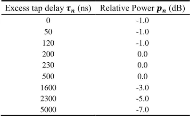
For the impulse response of the channel, the power delay profile of the 3GPP extended typical urban (ETU) channel model has been considered. It emulates the impulse response of a signal received in a strong multipath environment with a root-mean square (RMS) delay spread of around 991ns. Its coherence bandwidth, the frequency bandwidth for which the channel characteristics remain similar, is equal to 160 kHz. Its parameters are given in Table 1.
Table 1. Parameters of the power delay profile for the ETU channel model. Excess tap delay 𝝉𝒏 (ns) Relative Power 𝒑𝒏 (dB)
0 -1.0 50 -1.0 120 -1.0 200 0.0 230 0.0 500 0.0 1600 -3.0 2300 -5.0 5000 -7.0
ETU delay profiles have been used to evaluate the resilience of the candidate waveforms for this LPWA application. The channel models here described are used in Section 3 for performance evaluation.
3 Performance Evaluation
3.1 Range Performance Comparison
In this section, the performance (PER, sensitivity) of the waveform candidates under realistic frequency selective channels is studied and evaluated in terms of range and power consumption. These aspects represent critical elements for the LPWA systems. The performance investigation has been performed thanks to a link simulator and the simulation has been operated using the following parameters:
- Tone spacing Δf = 15 kHz (only for OFDM, SC-FDM and Turbo-FSK) - Nfft = 128, cyclic Prefix of size Ncp= 9 or 4.7µs.
- Packet size: 1008 bits of information
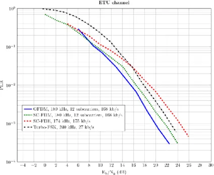
Performance in terms of packet error rate (PER) as a function of the Eb/N0 for the
waveform candidates is given in Figure 1. For these simulations, excepted for the turbo-FSK, the bandwidth and the throughput are equivalent to around 180 kHz and 170 kb/s respectively. This corresponds to 12 active carriers when multicarrier modulations are considered (OFDM, SC-FDM) with QPSK modulation and 1/3 for the coding rate. For the Turbo-FSK, a configuration with a 240 kHz bandwidth or 16 active carriers and throughput of 27 kb/s has been used. This is because the number of carriers has to be a power of 2. Turbo-FSK has been designed as an intrinsically low spectral efficiency waveform. In order to compare these air interfaces operating at different throughput and spectral efficiency, PER curves are provided as a function of Eb/N0. Figure 1
compares the amount of energy necessary to transmit an information bit for each technology with a limited and controlled amount of transmission errors.
OFDM presents the best performance compared to the other waveforms with a maximum gap of almost 4 dB with SC-FDE modulation for a PER of 10-2. SC-FDM is
slightly less performant than OFDM, followed by Turbo-FSK and SC-FDE.
Fig. 1. PER as the function of the Eb/N0 for OFDM, SC-FDM, SC-FDE and Turbo-FSK.
One key feature of LPWA connectivity is to achieve long-range transmission. Hence performance of Figure 1 should be revisited in terms of transmission range. We define the transmission range, d, as:
where 𝑃𝑇𝑋𝑑𝐵𝑚 is the transmit power in dBm, LHata(d) the path loss for a transmission
range of d and ρ the receiver sensitivity which is defined by (4).
𝜌 = (𝐸𝑏 𝑁0)
𝑑𝐵
+ 10 log10(𝐵𝜂) + 𝑁 + 𝑁𝐹, (4)
where B is the signal bandwidth in Hz, η the spectral efficiency in b/s/Hz, N the power spectral density of the thermal noise (N=-174 dBm/Hz), and NF the noise figure of the receiver. A NF equal to 6 dB has been considered in the following of the paper.
Since LHata(d) is an increasing function of the transmission range, and assuming PdBm
Tx is fixed and independent from the selected waveform, the transmission range can
only be increased by reducing the receiver sensitivity. Since N and NF are constant, transmission range can be increased by selecting the waveform that exhibits the lowest Eb/N0 for a targeted level of PER or by reducing the signal bandwidth and/or the spectral
efficiency.
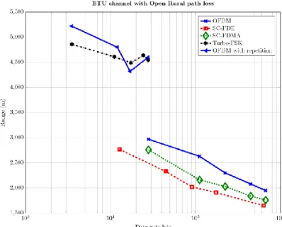
Fig. 2. Range as the function of throughput for communications through ETU channel for the
waveform candidates, OFDM, SC-FDE, SC-FDMA and Turbo-FSK.
Transmission range has been evaluated and is given in Figure 2 using the Open rural Hata model. Simulations have been performed for the proposed waveforms with bandwidths ranging from 45 kHz to 1 MHz and a spectral efficiency of 2/3 b/s/Hz for OFDM, SC-FDM and SC-FDE (QPSK, Rc=1/3). Transmit power of 14dBm and a
carrier frequency of 868MHz has been assumed. Turbo-FSK has also been plotted, but the waveform exhibit a much lower spectral efficiency. In order to provide a fair comparison with Turbo-FSK, the performance of OFDM (i.e. the best performing waveform) has been added with symbol repetitions in such a way that the spectral
efficiency is equivalent (8 repetitions have been used i.e. approximately 1/12 b/s/Hz). It can be observed that for the high bit rates, OFDM presents the best performance with the best range for any given data rate with a range of around 2 km at 700 kb/s. Concerning the low bit rates, OFDM and turbo-FSK have similar ranges between 4.5 km and 5 km with a slight advantage for OFDM for the very low throughput. For a given data rate (e.g. 30 kb/s, OFDM with and without repetition), best ranges are obtained for the modes with the wider bandwidth waveforms and with a lower spectral efficiency. This is because theses modes can take advantage of the frequency diversity brought by bandwidths significantly wider than the coherence bandwidth of the channel (160 kHz).
In this section, the performance in terms of PER and range has been assessed for each candidate waveform. OFDM associated with turbo coding seems to give the best performance for LPWA applications. However, the results presented so far did not take the impact of power consumption introduced by the different PAPR of the various waveforms. In the next section, an evaluation of the impact of the selected waveforms can bring on the power consumption is evaluated.
3.2 Power Consumption
Minimizing energy consumption is a very important design consideration for LPWA communication systems and therefore the impact of the physical layer on the power consumption must be investigated. The power consumption at the transmitter is considered as the dominant effect, notably the power consumption necessary to operate the power amplifier (PA) [10]. It has been shown in [11] that the energy consumption per information bit depends on the following parameters: the transmission duration, the PAPR, the drain efficiency of the radiofrequency PA and the circuit power consumption of internal electronic functions. If we denote E the total energy consumption required to send N bits, then the energy consumption per information bit Ea can be expressed by
[11]:
𝐸𝑎=𝐸𝑁≈
(𝜀𝛾) 𝐸𝑡+ 𝑃𝑐𝑇𝑜𝑛+ 2𝑃𝑠𝑦𝑛𝑇𝑡𝑟
𝑁 , (5)
with Pc the circuit power consumption, Psyn the frequency synthesizer power
consumption, Ton the transmission duration, Ttr the transient mode duration, 𝐸𝑡=
𝑃𝑡𝑇𝑜𝑛the transmission energy, 𝜀 the PAPR and 𝛾 the drain efficiency of the
radiofrequency PA. Pc, Psyn and Ttr can be considered as constants defined by the
particular transceiver structure in use. From this model, it is necessary to find the best tradeoff between the transmission duration and the PAPR in order to optimize the power consumption. This tradeoff depends on the modulation/constellation scheme. We will assess the evolution of the “estimated power consumption” as a function of the throughput (and/or the waveform used). The following parameters have been applied in order to evaluate Ea:
- Pc = 100 mW
- Psyn = Pc /2
- Ttr = 250 ms
- 𝐸𝑡=𝑃𝑡 𝑇𝑜𝑛 , 𝑃𝑡 = 14 dBm (25.12 mW)
The characteristic used for the PAPR 𝜀 and the drain efficiency of the RF PA 𝛾 is given in Figure 3a [11].
The energy consumption per information bit as a function of the data rate for different waveforms with different configurations is shown in Figure 3b. For a given waveform exhibiting a constant PAPR, the energy consumption per information bit linearly decreases when the data rate increases. This is because Ton is a linear function
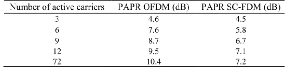
of the data rate. This can be explained as the transmitted power consumption is mainly dependent on the transmission duration of each data bit. This trend is particularly relevant for SC-FDE and for Turbo-FSK. For multicarrier modulations (OFDM and SC-FDM) the PAPR increases with the number of used sub-carriers and the modulation order (Cf Table 2). The energy consumption saved by the reduction of Ton is not fully
compensated by the increase of number of carriers necessary to increase the throughput. As a consequence the PAPR increase has a larger impact on power consumption than the transmission duration and the energy per transmitted bit is increased at the same time as the data rate (e.g. for OFDM, a data rate of 40 kb/s gives a Ea of around 2.10-2
mJ while a data rate of 200 kb/s gives an energy of 4.10-2 mJ per bit). Turbo-FSK
provides the most energy efficient option for low bit rates (around 10 kb/s). For the medium and the high bit rates, single carrier (SC-FDE) presents the lowest energy consumption per transmitted information bit as Turbo-FSK does not provide higher spectral efficiency options.
Fig. 3. (a) PA drain efficiency as a function of the PAPR (left).
Table 2. PAPR for OFDM and SC-FDM according to the number of active carriers. Number of active carriers PAPR OFDM (dB) PAPR SC-FDM (dB)
3 4.6 4.5
6 7.6 5.8
9 8.7 6.7
12 9.5 7.1
72 10.4 7.2
In section 3.1, it was concluded that OFDM provided the best range for any given data rate assuming a given transmit RMS power. However, in this section, we concluded that OFDM was the least power efficient of the four selected modulations. This has led to analyze which compromise should be considered in the context of LPWA communications. It seems notably that, for low data rate, constant envelope modulations such as Turbo-FSK are more suitable as performance level is similar while power consumption is much lower than for OFDM. For higher, data rates, OFDM seems to give an unrivalled performance gain.
3.3 Performance for LPWA applications
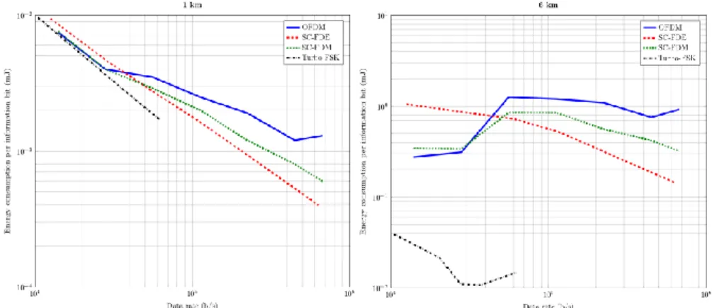
Since power consumption, operating range and throughput are key parameters for LPWA operations, it is necessary to further analyze which waveform is most adapted to the LPWA context. Power consumption per information bit as a function of the throughput for a given fixed range of respectively 1 km and 6 km has then been investigated. In this context, instead of considering fixed transmit power (of 14 dBm) and evaluate the associated reachable propagation range for a given selected waveform, power of the transmitter has been increased or reduced to reach the targeted propagation range (of respectively 1km or 6km) and a PER = 10-2. Results have been summarized
in Figure 4 ((a) for 1 km range and (b) for 6 km range).
For 1 km range, energy consumption per information bit is dominated by the circuit and frequency synthesizer power consumption (see (5)), transmit power evaluated to be equal to approximately -7 dBm for OFDM, -7.8 dBm for Turbo-FSK and -2.4 dBm for SC-FDE for 14 kb/s. Hence, the energy consumption per transmitted information bit is for lower data rates almost the same independently of the selected waveform. As the data rate is increased, the PAPR of the waveform is increased notably because the number of active carriers (and the bandwidth) of the multicarrier waveform is also increased. Difference of energy consumption per information bit is increased almost according to the subsequent increase in PAPR between Turbo-FSK and multicarrier modulations when the data rate is increased. For 6 km range, the system energy budget is rather different. Power consumption is dominated by the required transmission energy, Et. Estimated required transmit power is between 21dBm and 37dBm for the
highest data rates of OFDM. The required increase of power when data rate is increased is often not compensated by the shorter transmission duration. This is particularly the case for OFDM and SC-FDM.
Fig. 4. Energy consumption per information bit as the function of the throughput and for a given
range of: (a) 1 km (left), and (b) 6 km (right).
Assuming this scenario, Turbo-FSK provides for data rates lower than 60 kb/s the best energy compromise. OFDM is the least attractive waveform in terms of power consumption. SC-FDM and SC-FDE have intermediate power consumption levels but with level closer to OFDM than Turbo-FSK in particular when the range is larger than 1 km.
The performance results summarized in this section concluded that the most adapted waveform for LPWA operation is therefore highly dependent on the considered propagation scenario. When data throughput is preferred, OFDM should be considered. When range and good energy efficiency should be guaranteed, Turbo-FSK is better (for the low throughputs). Finally, when power consumption is of most importance, but without compromise on data throughput, SC-FDE or SC-FDM should be considered. This imposes some level of flexibility for the choice of the LPWA waveform. We introduce in the next Section an architecture of a physical layer adapted to the four here mentioned modes.
4 A new physical layer for LPWA
The level of flexibility and performance required by the LPWA scenarios for the physical layer leads us to exploit different waveforms. The set of selected waveforms are based on frequency domain processing with a prefix cyclic insertion in order to have a simple and robust equalization. These waveforms employ then common elements such as FFT/IFFT, frequency equalization, coder/decoder. Hence, a physical layer with multiple waveforms support using “frequency processing” can be considered as a new physical layer with an extended set of parameters for LPWA applications.
Fig. 5. Block diagram for a flexible physical layer transmitter adapted to LPWA system. The block diagram of this new waveform is shown in Figure 5. This block diagram corresponds to the merge of the four selected waveform candidates for LPWA applications: Turbo-FSK, SC-FDE, SC-FDM and OFDM. With a particular parameterization of each block we can provide the targeted waveform with the most adapted Modulation Coding Scheme. Its transmitter is composed of FEC encoding, interleaving and constellation mapping. A precoding DFT is solely used for SC-FDM and bypassed by the other modes. It is followed by a carrier mapping and IFFT: these modules are only applied to multicarrier modulations (SC-FDM, OFDM and Turbo-FSK). Finally, the insertion of a cyclic prefix and transmit filter common to all schemes complete the transmitter physical layer architecture.
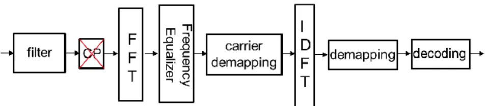
The architecture overview of the receiver is given in Figure 6. And follows the reverse structure of the receiver. It is interesting to note that in this case, the FFT is not bypassed for receiving any of the selected waveforms. This is because SC-FDE considers equalization in the frequency domain. IDFT is then applied for SC-FDM and SC-FDE modes.
Fig. 6. Block diagram for physical layer the receiver of the LPWA-CB system. Finally, although this paper does not analyze the overhead in complexity introduced by the support for multiple waveforms, the flexibility introduced should not lead to significant cost overhead in comparison to a less flexible approach. Hardware complexity of a physical layer is often dominated by its receiver. IDFT is the main block that should be bypassed at the receiver when not required (Turbo-FSK, OFDM). Since FFT and IDFT modules are highly optimized for implementation, these blocks have often limited complexity impact on the design [12]. This preliminary analysis should however be confirmed by a more hardware complexity thorough study.
5 Conclusion
The first generation of LPWA systems have brought coverage for a long battery life. Future generations are expected to provide faster data rates and/or lower latency for
similar battery lifetime to extend the range of applications the technology can deliver. These new requirements for LPWA applications have led to reconsider the physical layer for these types of systems. A new flexible approach for LPWA has been introduced and is imposed by the contradictory requirements of long-range, low power consumption and higher throughput. A performance analysis has concluded that OFDM is the most appropriate waveform for throughput performance when the constraints on the power consumption are relaxed, while Turbo-FSK presents the best performance in terms of range and energy efficiency when the throughput is low. Finally, if a compromise between range, throughput and power consumption is desired, either SC-FDE or SC-FDM is more appropriate. A block diagram of transmission and reception for this new approach has been proposed and described.
Future work should further study common approaches of synchronization mechanisms for the different options of the physical layer. This include timing and frequency synchronization and channel estimation. This should be completed and refined before hardware architecture implementation and its associated complexity evaluation of the flexible concept.
References
1. Gartner, Inc.: Gartner Says 4.9 Billion Connected "Things" Will Be in Use in 2015. [Online] http://www.gartner.com/newsroom/id/2905717
2. Raza U., Kulkarni P., Sooriyabandara M.: Low Power Wide Area Networks: An Overview. In IEEE Communications Surveys & Tutorials, Vol. 19, No. 2 (2017)
3. Berg Insight: Cellular and LPWA IoT Device Ecosystems. (2017)
4. Springer A., Gugler W, Huemer M., Reindl L., Ruppel C. C.W., Weigel R.: Spread spectrum communications using chirp signals. In IEEE Proc. Eurocomm, pp.166 -170 (2000). 5. ETSI: LTE; Evolved Universal Terrestrial Radio Access (E-UTRA); Physical Channels and
modulation. In ETSI, 3GPP TS 36.211 version 13.2.0 Release 13 (2016).
6. Roth Y., Doré J.-B., Ros L., Berg V.: A Comparison of Physical Layers for Low Power Wide Area Networks. In: 11th EAI International Conference on Cognitive Radio Oriented Wireless Networks (Crowncom), Grenoble (2016).
7. Okumura Y., Ohmori E., Kawano T., Fukuda K.: Field strength and its variability in VHF and UHF Land-Mobile radio service. In Review of the Electrical Communication Laboratory, Volume 16, No. 9-10, pp. 825–873 (1968).
8. Hata M.: Empirical Formula for Propagation Loss in Land Mobile Radio Services. In IEEE Transactions on Vehicular Technology, Volume 29, No 3, pp. 317–325 (1980).
9. European Cooperation in the Field of Scientific and Technical Research, EURO-COST 231: Digital Mobile Radio Towards Future Generation Systems. In COST 231 Final report. [Online] http://www.lx.it.pt/cost231/
10. Raja M.K., Chen X., Lei Y. D., Bin Z., Yeung B. C. and Xiaojun Y.: A 18 mW Tx, 22 mW Rx transceiver for 2.45 GHz IEEE 802.15.4 WPAN in 0.18-m CMOS. In Solid State Circuits Conference (A-SSCC), IEEE Asian, Beijing (2010).
11. Cui S., Goldsmith A. J. and Bahai A.: Energy-Constrained Modulation Optimization, IEEE Trans. on Wireless Communications, pp. 2349--2360, Vol. 4, N°5 (2005).
12. Berg V., Dore J.-B., and Noguet D.: A multiuser FBMC receiver implementation for asynchronous frequency division multiple access. In 2014 17th Euromicro Conference on Digital System Design, pp. 16–21 (2014).