HAL Id: cea-02378299
https://hal-cea.archives-ouvertes.fr/cea-02378299
Submitted on 25 Nov 2019
HAL is a multi-disciplinary open access
archive for the deposit and dissemination of
sci-entific research documents, whether they are
pub-lished or not. The documents may come from
teaching and research institutions in France or
abroad, or from public or private research centers.
L’archive ouverte pluridisciplinaire HAL, est
destinée au dépôt et à la diffusion de documents
scientifiques de niveau recherche, publiés ou non,
émanant des établissements d’enseignement et de
recherche français ou étrangers, des laboratoires
publics ou privés.
Y. Sarazin, J. Hillairet, J.-L Duchateau, K Gaudimont, R Varennes, X.
Garbet, Ph. Ghendrih, R. Guirlet, B. Pégourié, A. Torre
To cite this version:
Y. Sarazin, J. Hillairet, J.-L Duchateau, K Gaudimont, R Varennes, et al.. Impact of scaling laws on
tokamak reactor dimensioning. Nuclear Fusion, IOP Publishing, 2019, 60, pp.016010.
�10.1088/1741-4326/ab48a5�. �cea-02378299�
dimensioning
Y. Sarazin, J. Hillairet, J.-L. Duchateau, K. Gaudimont,
R. Varennes, X. Garbet, Ph. Ghendrih, R. Guirlet, B. Pégourié, A. Torre
CEA, IRFM, Saint-Paul-lez-Durance, F-13108, France. E-mail: yanick.sarazin@cea.fr
26 September 2019
Abstract. A simple and comprehensive method is derived and used to quantify the impact of scaling laws on tokamak reactor dimensioning. Assuming prescribed geometrical coefficients, we find the ensemble of possible triplets R, B and normalized beta βN which allow one to reach target fusion gain Q and fusion power Pfus, at arbitrary Greenwald fraction. The model is generic and derived for any scaling law of the energy confinement time. Using the IPB98(y,2) scaling law [ITER Physics Basis Expert Groups on Confinement and Transport and Confinement Modelling and Database, ITER Physics Basis Editors 1999 Nucl. Fusion 39 2175] leads to ITER specifications, as expected. The recently proposed new scaling law for H-mode plasmas (DS03, [A.C.C. Sips et al. 2018 Nucl. Fusion 58 126010]) is shown to lead to modest changes to the dimensioning, except for B which could be significantly smaller for the same target performance. The impact on the dimensioning of critical exponents of the scaling law – both regarding engineer and dimensionless variables – is assessed, pushing for their determination with refined accuracy. Finally, the method is applied to a DEMO-like machine. The DS03 scaling law is found to have favorable consequences on the dimensioning as compared to IPB98(y,2), provided one is able to operate at largerβN, which can reveal challenging in a reactor aiming at zero disruption. Importantly, the opposite scaling of both scaling laws with respect to the aspect ratio are shown to have significant consequences on the optimal choice of this critical parameter.
Keywords: Tokamak design, scaling law, aspect ratio, ITER, DEMO
1. Introduction
The aim of fusion energy research is to provide fusion power Pfus minimizing the required auxiliary heating power, Paux, and therefore maximizing the
amplifica-tion factor Q = Pfus/Paux. Designing next step
experi-ments in ITER or a tokamak reactor combines techno-logical and physics based constraints. Given a target fu-sion power Pfuswhat are the constraints that determine the key parameters, namely the size and magnetic field of a tokamak reactor? The answer is not straightfor-ward, and optimum trade-off must be addressed. Tech-nological issues are surely among the important ones, either regarding thermal and neutron loads on diver-tor and plasma wall materials, respectively [12, 28], or the maximum magnetic field which can be delivered by industrial-type super-conductors [10]. In that respect, an effort is devoted to explore the impact on the design of DEMO – the possible successor of ITER on the route towards a fusion power plant [12] – of uncertainties regarding both critical engineering parameters [4, 27] and that of the tritium cycle [3]. Regarding plasma physics issues, the route to fusion energy using mag-netic confinement is paved with experimental findings, in particular via scaling laws. Uncertainties are signif-icant [35], especially when compared to that introduced by technology. At the crux of the design effort, the fu-sion gain Q is inherently governed by the energy con-finement time. The knowledge of the latter is based on an empirical scaling law. Extrapolation from present experimental data must be done to address the operat-ing point of ITER and even more of DEMO. The best scaling laws exhibit standard deviations of about 16%. Although this overall reliability might look acceptable at first sight, it actually masks much larger uncertain-ties with respect to some critical parameters for which a sufficiently unbiased data base is still lacking.
The objective of this paper is to investigate how the form of the scaling law of the energy confinement time
τE, dependencies and uncertainties, impacts the design
of a tokamak aiming at burning plasma operation, typ-ically Q ≥ 5. The approach is based on a 0-dimensional analysis (with some refinement to account for temper-ature peaking) allowing for a step-by-step derivation of all constitutive relations, including the comprehensive computation of all the constants required in determin-ing quantitative parameters. The calculation is generic with formal expressions, hence allowing further inves-tigation, e.g. by considering different scaling laws or machine specifications. Particular attention is payed to size and magnetic field because these drive the cost and in many respects feasibility of a given design. Two main aspects are considered for a given a reference empirical scaling laws for the energy confinement time proposed in the literature: on the one hand how prescribed target
fusion performance translate in terms of machine size, and on the other hand how the uncertainties associated to the scaling laws propagate into a range of machine sizes. In that respect, a known feature of the energy confinement time scaling law is the strong dependence in the dimensionless parameter ρ∗, ratio of the
char-acteristic Larmor gyration length to the tokamak mi-nor radius. Results obtained here indicate that even a small uncertainty on this dependence has a big impact on the required size. Calculation of this parameter de-pendence and related uncertainty can then be traced in the empirical data. One can then define specific inves-tigation steps to reduce the uncertainty with dedicated experiments and simulations [2]. The present paper aims at giving pedagogical insight into the art of toka-mak design as well as providing a tool to investigate some aspects of uncertainty propagation. It proves ef-fective in recovering main findings and unraveling new features.
The empirical scaling law is characterized by a de-pendence on a large set of variables. Some are dimen-sionless, typically those describing the geometry of the magnetic surfaces. The others can be split into engi-neering parameters, those that are directly set by the machine operation, while others are physical param-eters that result from plasma performance. The two sets are combined to define a set of dimensionless pa-rameters,ρ∗, ν∗and β, the latter two being the colli-sion frequency normalized to the transit time frequency and the ratio of the kinetic pressure over the magnetic pressure, respectively. Setting the geometry and as-suming the fusion cross section to exhibit a quadratic dependence on the thermal energy, it is possible to re-strict the unknowns to four parameters, conveniently the plasma density and thermal energy and two critical engineering parameters, namely the torus major radius and magnetic field. The procedure that is followed is to set the output fusion power, and, via a target fusion gain to prescribe the energy confinement time. This yields two constrains. The physical parameters density and temperature are then changed into two parameters that are used to evaluate the distance to known oper-ating limits, density limit on the one hand and MHD limit on the other hand. Due to the quadratic depen-dence of fusion power on the density, one can consider that a natural constraint is to set the density close to the limit, typically 20 % below the limit. The output of the calculation is then sets of values of major radius and magnetic field determined in terms of the parame-ter describing the MHD limit. This well defined process provides a generic framework for such studies.
The paper is organized as follows. The constitutive relations are recalled in section 2, where the explicit
expressions of all the constants are derived. Section 3 shows how these relations govern the dimensioning of tokamak, mainly in terms of magnetic field B and major radius R. In particular, the ITER characteristics are recovered provided the IPB98(y,2) scaling law forτEis
considered [17]. The impact on the dimensioning of the newly proposed scaling law for ELMy H-mode plasmas is also addressed [29], as well as that of the scaling exponents of the critical dimensionless variables ρ∗,
ν∗ and β. Finally, implications on the characteristics
of DEMO are briefly discussed, including a critical discussion regarding the dependence on the aspect ratio.
2. Key Physics input for reactor design
Preliminary remark regarding the choice of units: In the following, unless specified, the International System of Units (SI) is used. However, for simplicity, some of the most used parameters are not expressed in SI units, these are identified with hats “...”. The followingb specific units are employed:
• n is the density in 10b
19m−3:
b
n = 10−19n [m−3]
• bT and E are the thermal energy and any otherb energy, respectively, expressed in keV : T =b (10−3kB/e) T[K ]andE = (10b −3/e) E[J]
(with kB the Boltzmann’s constant and e the
elementary electric charge)
• bIpis the plasma current in MA:bIp= 10−6Ip [A]
• bP is the power in MW:P = 10b −6P[W]
In addition, M is the mass in Atomic Mass Unit. Also, for the sake of simplicity and in marked difference with respect to advanced system codes [20, 26], flat profiles of density and current are considered. However, taking into account the temperature peaking has proven to be important to recover the target performance of ITER working conditions.
Among the available control parameters, some are chosen as input parameters while others will be the output of the analysis. For the sake of simplicity, the geometry of the magnetic surfaces is given. Conse-quently, several dimensionless control parameters spec-ifying the shape, aspect ratio – A= R/a. = ε. −1,
elon-gation κ and triangularity δ – are chosen to be input
parameters. The target fusion performance of the ma-chine is also chosen to be prescribed since it is a primary objective of a fusion reactor. We therefore set as inputs the fusion power Pfus and fusion gain Q – equivalently the auxiliary heating power.
In steady state conditions and for chosen nuclear fusion reaction, here D-T fusion, the gain Q and Pfus determine the energy confinement timeτE. The
latter is assumed to follow a known scaling law, which
depends on density, temperature, magnetic field and major radius, while the fusion power depends on density and temperature. Two relationships are thus obtained that constrain the set of parameters. The following steps of the analysis are standard, thus to a large extent comparable to that followed by H. Zohm and coworkers [36] (a major difference being that we explicitly derive and give the expressions of all the constants). Among the four independent control parameters, the magnetic field and major radius are engineering parameters that can readily be addressed in terms of feasibility issues. Indeed, technological limits – limits regarding industrial superconductors, mechanical resistance to stresses and forces, limits regarding the acceptable power heat flux impacting plasma facing components [28] – and economical considerations – the cost of the machine is basically expected to scale like the magnetic energy, i.e. B2R3 – set clear bounds to what can reasonably be achieved. Conversely, density and temperature are constrained by plasma physics issues. In fact, one connects here these two parameters to critical parameters that appear to bound the operational space of present experiments. The two main soft limitations that we consider are the Greenwald density limit and the so-called normalized beta (βN) limit. As a matter of fact,
these allow one to define upper bounds – although soft ones – to the accessible density and temperature. In the following we show how the set of engineering parameters can be reduced to the four independent parameters and we then relate these to the two chosen operational limits. We also bridge these parameters to the dimensionless parameters.
2.1. Density and Greenwald limit
As stated in a topical review on the subject [16], “an independent limit on plasma density is observed in confined toroidal plasmas. [...] In tokamaks, [...] there is strong evidence linking the limit to physics near the plasma boundary [...]”. As a matter of fact, the so-called Greenwald density nG is not a sharp density
limit, rather a soft one, since discharges with peaked density profiles can well operate above this value. So far, there is no widely accepted, first principles model for the density limit. Yet, the focus is currently either on mechanisms which lead to strong edge cooling, or on collisionality enhanced turbulent transport.
From [13, eq.(14.146)], the most common empirical scaling for (line-averaged) density limit is the following:
b nG= C. n
b Ip
ε2R2 (1)
with R the major radius of the tokamak,Ibpthe plasma
current and Cn= 10/π ≈ 3.18. Integrating the
cross-section and using Stokes’ theorem provides the relationship between Ip and the magnetic field (µ0=
4π10−7H.m−1): Z S(∇ × B) · dS = µ0 Z Sj · dS → I CB · d` = µ0Ip
Let us denote Lcs= 2πa × F the length of the poloidal
cross-section, with F some factor depending on the plasma shape. F = 1 for circular plasmas. If accounting for elongation only, it can be approximated by F = p
(1 + κ2)/2, or even by F = κ as in [17]. A more accurate
expression is proposed in [18, eq.17] accounting for triangularity. This leads to:
LcsBp= µ0Ip
with Bpthe poloidal component of the magnetic field at
the separatrix. In the limit of large aspect ratios, it is related to the safety factor q at the separatrix (actually, it is usually taken slightly inside the separatrix, at 95% of the poloidal magnetic flux): q= εB. t/Bp with
Btthe toroidal component of the magnetic field at the
magnetic axis. Then it comes, replacing Bt by the
magnitude B of the total magnetic field (since Bp¿ Bt):
b Ip= CIε
2
q RB (2)
with CI= 2πF 10−6/µ0(alternatively, the form factor F
could be extracted from the definition of CI, C0I= CI/F,
and incorporated in the one of q, then leading to the so-called cylindrical safety factor qc yl= q/F sometimes
encountered in the literature: Ibp = C0I ε
2
qc yl RB; this
latter relation is equivalent to assuming a cylindrical plasma with Lcs= 2πa, hence the name). Using the
expression of the plasma current (2),nbG can be recast
as follows: b
nG= CnCI
B qR
Finally, one introduces the normalized density (also called the Greenwald fraction) nN= n/n. G, so that:
b
n = CnCInN
B
qR (3)
2.2. Pressure andβNlimit
The plasma betaβ is the ratio of the plasma pressure p = 2nkBT (the factor 2 comes from the electron and ion
contributions, assumed to have the same temperature) to the magnetic pressure B2/2µ0:
β% . = 100 p B2/2µ 0= Cβ b nTb B2 (4)
where β% = 102β is expressed in percent and Cβ = 4. 102µ0× 1019× 103e ≈ 0.805.
Several modes (such as e.g. kink, tearing or ballooning modes) become MHD unstable above certain thresholds of pressure gradient and plasma current,
so that one can expect that β will be subject to a
stability limitation which will likely depend on the plasma current. A stated in [33], “the concept ofβ limit
is not precise. Stability depends on profiles, and any optimization introduces the questions of which modes of instability to include and what mode numbers to allow. Furthermore, there is uncertainty as to the severity of the nonlinear consequences of the various modes. Nevertheless the intrinsic usefulness of a concise analytic β limit in assessing possible tokamak performance has prompted a number of investigations”. It turns out that the β limit, i.e. the maximum stable β, scales approximately like ε/q, which can be recast as (µ0/2π) Ip/aB from the above relations. We
shall defineβmas follows:
β%É βm= g.
b Ip
aB
The coefficient of proportionality g depends on the considered instabilities. The so-called "Troyon limit" [31] puts this coefficient to 2.8. It is usual to introduce the normalizedβ, called βN, defined by [13,
eq.(13.146)]:
β%= β. N
b Ip
aB (5)
Then, the stability limit simply reads βN < g.
Interestingly, using the above expression and that of the plasma current (2), the plasma pressure can be expressed as a function ofβNand B:
b nT = Cb −1β βN b IpB εR = CI Cβ ε qβNB 2 (6)
2.3. Expression of the fusion power
Since it has the highest fusion reaction rate 〈σv〉, the D-T reaction is the targeted fusion reaction as the most accessible (maximum reactivity at lowest temperature) of all fusion reactions [8]:
D + T −→4He (3.56 MeV) + n (14.03 MeV)
The total released energy is EDT = 17.59 MeV =
2.82 × 10⁻¹²J per fusion reaction (this value is worth comparing to the 200 MeV released by 235U fission. Yet, the energy release per nucleon, i.e. per kilogram, is approximately 4 times larger for fusion than for fission reactions). Incidentally, notice that the ratio of the total energy to that carried by the alpha particles
λ= 17.59/3.56 ≈ 4.94 is not exactly equal to 5. This is. due to relativistic corrections which cannot be ignored. This point is clarified in Appendix A. Yet, such a small difference – especially with respect to the uncertainty of the scaling laws – is not critical for our purpose.
The total thermonuclear fusion power Pfusreads: Pfus= nDnT〈σv〉DTEDTVt
with nD and nT the deuterium and tritium density
and Vt= 2π2κRa2 the volume of the tore. Assuming a
stoichiometric mixture with nD= nT = n/2 with n the
electron density, and using the expression of Vt, one
gets: Pfus= π2κε2 2 R 3n2 〈σv〉DTEDT
〈σv〉DT depends on temperature only. Its maximum
is reached at about T ≈ 66.5keV (≈ 770.106 K). This is however not the optimal temperature to operate a controlled fusion reactor. Indeed, on the one hand, achieving self-sustained burning conditions requires the Lawson criterion to be satisfied. It states that the product of density and energy confinement time should exceed some threshold depending on temperature only, scaling like T/〈σv〉DT. This threshold
turns out to be minimal at T ≈ 26keV. On the other hand, arguing that, rather than density n and temperature T independently, β governs the maximal
achievable power in a fusion reactor, one is then led to consider that the optimal temperature is the one which maximizes Pfus ∝ β2〈σv〉DT/T2. At prescribed β, the
peak power is obtained for T ≈ 13keV.
In light of the above arguments, temperature is usually assumed to be in the range 10.3-18.5 keV, for which the reactivity 〈σv〉DT can well (with about 10%
error) be approximated by [8]: 〈σv〉DT≈ 1.18 10−24Tb2m3s−1
It should be checked a posteriori that this assumption regarding the temperature range is well fulfilled by the proposed machine settings. All in all, one gets (in MW):
b Pfus= Cf usκε2R3nb 2 b T2 (7) with Cf us ≈ 17.59 × e × 1.18 10−24× 102×19× π2/2 ≈
1.64 10−3. When expressed in terms ofβ
Nby using (6), it reads: b Pfus= Cf usC2I C2 β κε4 q2 β 2 NR 3B4 (8)
This total fusion power is distributed amongα particles and neutrons:
Pfus= Pα+ Pn= λ Pα
where we will retain the valueλ = 4.94 hereafter. 2.4. Expression of the fusion gain
The plasma amplification factor is defined as the ratio of the fusion power to the auxiliary heating power: Q=. Pfus
Paux
(9) Importantly, Q does not encompass – by far – the entire question of the energetic efficiency of a fusion reactor. In particular, it does neither account for the energy
required to pump the coolant which circulates in the blankets nor for the conversion factor of thermal to electric energy, among others (noticeably, the cryogenic consumption associated to the use of superconductors does not represent the dominant contribution).
At steady state, Paux is related to Pfus. Indeed, balancing plasma heating sources and power losses leads to:
PS ce= P. α+ PΩ+ Paux= Pl oss= P. rad+ Ptr
with PΩ the ohmic heating, Prad the radiated power
and Ptr the power lost due to transport across the
magnetic surfaces, mainly governed by turbulence. Here, it is implicitly assumed that the energy carried by α particles is entirely transfered to the D-T fuel. We shall note Pnet = PS ce− Prad the net
power received by the plasma, so that the power balance also reads Pnet = Ptr. For the sake of
simplicity, we will assume hereafter that the radiative losses (mainly due to Bremsstrahlung and synchrotron radiation, plus line radiation if the plasma gets polluted by heavy impurities) scale like the total heating power: Prad = (1 − γrad) PS ce, with 0 ≤ γrad≤ 1 some
prescribed coefficient, and that the ohmic contribution is negligible. Alleviating these assumptions in the model is left as future works. In this framework, the net heating power simply reads:
Pnet= γrad(Pα+ Paux)
which is also equal to Ptrat equilibrium.
The net power can therefore be expressed in terms of the fusion power and of the amplification factor: Pnet= γradPfus 1 + Q/λ
Q
Let us remark that there is actually an issue regarding the amount of radiated power which has to be counted as core radiation, and hence subtracted from PS ceso as
to get the power transported across the separatrix. This distinction is critical to know whether the plasma is expected to be in H-mode or not, as further discussed in section 3.5 (cf. footnote 3). This may reveal particularly important for discharges with large radiation, as expected e.g. in DEMO. Finally, replacing Pfus by its expression (7) leads to:
b Pnet= γradCf usκε2R3nb 2 b T21 + Q/λ Q (10)
2.5. Triple product and scaling law
Heat transport losses are not yet predictable from first principle simulations. Their estimate hence relies on multi-machine empirical scaling laws for the energy confinement timeτE, defined as the ratio of the thermal
internal energyW overc Pbtr. Noticing that (in [MJ]):
c W=. 3 2nb ¡ b Te+ bTi¢ Vt= Ctrκε2nbT Rb 3
Table 1. Coefficients of a few scaling laws forτE(theαRexponent of the L-mode scaling law has been modified so that the scaling law fulfills Kadomtsev constraint, as suggested in [17, p.2206]). Name IPB98(y,2) DS03 L-mode
Ref. [17, eq.(20)] [29] [17, eq.(24)] CSL 0.0562 0.028 0.023 αM 0.19 0.14 0.20 ακ 0.78 0.75 0.64 α² 0.58 0.30 −0.06 αn 0.41 0.49 0.40 αI 0.93 0.83 0.96 αR 1.97 2.11 1.78 αB 0.15 0.07 0.03 αP −0.69 −0.55 −0.73
assuming Tbe = bTi = bT and with Ctr = 6π2× 1019×
10−3e ≈ 0.095, one readily obtains:
b Ptr=. c W τE= Ctrκε 2nbT Rb 3 τE (11) Equating (10) and (11) leads to the expression of the triple product nTτEas a function of Q only:
b nTbτE= Ctr γradCf us Q 1 + Q/λ (12)
The usual scaling laws forτEproposed in the literature
take the following generic form, when expressed in engineer variables: τE= CSLMαMκακεα²nb αn b IαI p RαRBαBPbαnetP (13) where CSL and the αX coefficients are prescribed
parameters. The values for some scaling laws are given in Table 1. ReplacingIbpand Pbnet= bPtr by their
expressions given in (2) and (10) respectively leads to the expression of nbTbτE as a function of the sole
dimensional parameters (n,bT, R, B):b b nTbτE= CSLCIαI(γradPbfus)αPMαMκακεα²+2αIq−αI ×nb 1+αn b T RαR+αIBαB+αI µ 1 + Q/λ Q ¶αP (14) Arguing that n andb T (yet assumed in the rangeb [10.3, 18.5]keV here) can hardly be constrained by themselves, one is well advised to replace (n,b T) byb (nN,βN) using (3) and (6). These new physical relevant
variables provide a natural way to constrainn andb T onb the basis of soft or hard MHD limits. Further noticing that the left hand side of (14) depends on the fusion gain Q only (12), one obtains the following relationship:
µ Q γrad(1 + Q/λ) ¶1+αP = CSLCαnnCγIICf us/(CβCtr) × bPαP fusM αMκακεγ²q−γInαn NβNR γRBγB (15) withγI= 1 + αn+ αI,γ²= 1 + α²+ 2αI,γR= αR+ αI− αn andγB= αB+ αn+ αI+ 2.
3. Tokamak reactor dimensioning
Equations (8) and (15) provide the two independent re-lations which relate (R, B,βN, nN) to (Q, Pfus). Prescrib-ing the two latter quantities allows one to obtain the ensemble of solutions. For the sake of simplicity, we will hereafter reduce the dimensionality of the prob-lem by prescribing nN= 0.85, which is often reported as
the target value for ITER plasmas. (R, B,βN) solutions
then lie on the intersection of the two surfaces defined by (8) and (15). The method will first be applied using IPB98(y,2) scaling law, and shown to allow one to re-cover ITER main characteristics. Secondly, the impact of some characteristics of the scaling law will be evalu-ated and discussed. Finally, the case of DEMO will be considered.
Before proceeding, we will slightly refine some of the coefficients derived in the previous section so as to account for additional physics. Indeed, the coefficients considered up to now are not accurate enough to allow one to easily recover ITER dimensions.
3.1. Refined physics
One introduces the following refinements, accounting for α-particle dilution, temperature peaking and
different ion and electron temperatures:
(i) fα = n. H e/ne the fraction of α particles, which
is governed by both particle transport and the pumping efficiency (cf. Appendix B).
(ii) fp= 〈T. 2〉/〈T〉2 the peaking factor of the
tempera-ture profile (the density profile is assumed to be flat), where the brackets 〈...〉 denote volume aver-age. This profile is basically assumed to have a parabolic shape.
(iii) θi= T. i/Tethe ratio of ion to electron temperatures.
In ITER and in a fusion reactor, most of the heating source will go to the electrons, so that one expects
θi< 1.
As discussed below, several coefficients are modified by these additional variables:
Cf us→ Cf us× (1 − 2 fα)2θ2i× fp
Ctr→ Ctr×1 + θi− fαθi
2 Cβ→ Cβ×1 + θi− fαθi
2
The corrections regarding Cf usresult from the fact that
Pfus scales like 〈nDnTT2i〉, with nD = nT = 0.5 (1 −
2 fα)ne so as to fulfill electro-neutrality (nD+ nT+
2nH e= ne), and 〈T2i〉 = fp 〈Ti〉2 by definition ‡. As
expected, α particles are responsible for a dilution
‡ Consider the following temperature profile: T = Ta+(T0−
Ta)¡1− ρ2¢νT, withρ =r/a and Taand T0the temperatures at the
Table 2. Typical ITER parameters (cf. [18]). q ε−1 κ δ n N 3 3.1 1.7 0.33 0.85 fα M fp θi γrad 0.035 2.554 1.35 1/1.15 0.7
Table 3. Numerical values of the coefficients introduced in section 2. Cn CI Cβ Ctr Cf us
3.183 13.144 0.741 0.087 1.45 10−3
effect. The correction regarding Ctrand Cβis due to the
fact that both the power transport andβ scale like the
total pressure which reads:P
snsTs= neTe(1+θi− fαθi)
with the assumption that Tα = Ti. In addition, the
effective mass M simply derives from fα. Indeed, one has: (nD+ nT+ nH e) M= n. DMD+ nTMT+ nH eMH e=
ne{(MD+ MT)(1 − 2fα)/2 + fαMα}, with MD= 2, MT= 3
and Mα= 4. Then it comes: M = 5 − 2fα
2(1 − fα)
For the sake of simplicity and because their nature and respective concentrations are still subject of active research, other impurities are not considered in this work. These would modify various coefficients, including Cf us, Ctr, Cβ and M. Finally, we will
hereafter retain the expression proposed in [18] for F, including the effect of elongationκ and triangularity δ.
In this case, the CI= (2π10−6/µ0) × F coefficient reads
as follows: CI= 2π10−6 µ0 × (1.17 − 0.65ε)£1 + κ2(1 + 2δ2 − 1.2δ3)¤ 2 (1 − ε2)2
The set of ITER characteristic parameters is given in Table 2, mostly taken from [18]. The numerical values of the coefficients introduced in section 2, and accounting for the above refinements, are given in Table 3.
3.2. Recovering ITER characteristics
Two independent expressions ofβN with respect to R
and B are provided by equations (8) and (15). The intersection of these two surfaces draws a line in the (R, B,βN) plane. The system can be recast so as to
reads: fp = 〈. T2〉/〈T〉2=n2 ¯T2a+2 ¯TaT0+(1+ νT)T02 o
(T0+T¯a)−2×
(νT+1)/(2νT+1) where ¯Ta= ν. TTa. Then, taking Ta =0.1 keV,
T0=12 keV andνT=1.07 leads to the chosen value for fp: fp=1.35.
Also, the ratio of the core temperature over the average one reads: T0/〈T〉 =(1+ νT)(1+T¯a/T0)−1≈2.05.
eliminateβNin one of the two equations:
βN = Ã C2 β C2ICf us q κε4 b Pfus R3B4 !1/2 (16) µ Q γrad(1 + Q/λ) ¶1+αP = CSLCαnnCγII−1C 1/2 f us/CtrPb αP+12 fus × MαMκακ−12εγ²−2q1−γInαn N × RγR−32BγB−2 (17)
Figure 1 shows the solutions in the case of the IPB98(y,2) scaling law. We recall here that all other parameters but (R, B,βN) are fixed and given in table
2, in particular the safety factor q. There is a priori an infinity of possible triplet solutions (R, B,βN)
(intersection points of any vertical line with x-axis and the red and blue lines). Noticeably, B and R exhibit large variations despite modest variations of
βN: forβNin the range 1.57 ≤ βN≤ 2.07, the acceptable
couples (R, B) are in the range 2 ≤ R[m]≤ 10 and 3.84 ≤
B[T]≤ 11.19. B increases with βN, while R decreases.
Basically, large values of βN – hence small R – are
constrained by the so-called “radial build” [10], i.e. the necessity to have enough space for the central solenoid, the superconducting coils, the vacuum vessel and the neutron shields. Conversely, small values ofβN– hence
large R and small B – may reveal too costly assuming the cost scales typically like B2R3– although one might argue that less expensive superconductors (which can amount up to 25% of the total cost [11]) might be used in this case, e.g. NbTi instead of Nb3Sn [9].
Figure 1. Values of R and B as a function ofβNwhich fulfill both equations (8) and (15) when using the IPB98(y,2) scaling law. The solution at βN≈1.7 is close to the ITER specifications RI T ER= 6.2m, BI T ER=5.3T. The plasma is supposed to be in H-mode if the
ratio Ptr/PL−H(see text for definitions) is above unity. The plateau
durationτplateauis discussed in section 3.3.
Figure 2. Normalized density, temperature, plasma current and energy confinement time associated to the (R, B) couples of figure 1. The dashed horizontal lines correspond to the interval of temperatures where〈σv〉scales like T2.
be calculated from the previous relations: b Ip= CIε2 RB q b n = CnCI B nN qR b T = ε CnCβ RBβN nN τE= CtrCβ γradCf usCI Q 1 + Q/λ q εβNB2
These values are displayed on figure 2. Density exhibits the largest variations. It increases with βN while
temperature and current decrease. Notice that T is always close to the domain of validity of our analysis, i.e. 10.3 < bT < 18.5. The error regarding the estimate of the D-T fusion rate 〈σv〉 keeps typically below 10% for temperatures above ∼ 9.3keV and below ∼ 19.2keV.
Interestingly, it appears that the triplet (R, B,βN) =
(6.2 m, 5.3 T, 1.7) is a possible solution of the problem. This set of parameters is consistent with ITER spec-ifications. In this case, density, temperature, current and confinement time are also in fair agreement with published values: n ≈ 1.01 1020m−3, T ≈ 9.0keV, I
p≈
14.9 MA and τE ≈ 3.1 s. Also, the heat power
cross-ing the separatrix amounts to aboutPbtr≈ 106 MW, well
above the L-H power threshold ofPbL−H∼ 87 MW esti-mated from the empirical scaling law of reference [25] (cf. dashed-dotted line on figure 1). Finally, assum-ing an e-foldassum-ing length of the heat fluxλq≈ 5.10−3m in
the scrape-off layer, one would expect about 27 MW.m−2 on the divertor target plates (considering an inclination angle of the tiles of 30◦and a flux expansion of 5 as com-monly retained values). This would require additional radiation at the edge to keep below the technological
limit of about 10 MW.m−2in steady state.
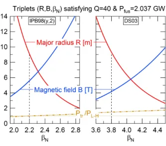
The same exercise is performed when using the zero-β DS03 scaling law (see section 3.4 for the
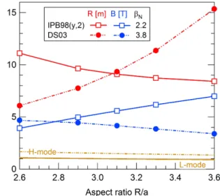
definition) proposed in [29]. The results are displayed on figure 3, with prescribed parameters given in table 2. The corresponding dimensional variables are plotted on figure 4. The same trend is observed for R and B with respect to βN, but with much larger variations.
It readily appears that the ITER specifications are not part of the solutions. One possible choice would be to consider the same radius R = 6.2m, which would then require B ≈ 4.42T and βN ≈ 2.43 to achieve Q = 10
and Pbfus= 500 MW. In this case, density, temperature, plasma current and energy confinement time would be equal to n ≈ 8.4 1019m−3, T ≈ 10.7keV (in between the
acceptable limits 10.3 and 18.5), Ip≈ 12.5 MA and τE≈
3.1 s. Again, the power crossing the separatrix Pbtr≈
106 MW exceeds the L-H power threshold, estimated at b
PL−H∼ 66 MW from [25].
Figure 3. Same as figure 1 when using the DS03 scaling law [29].
3.3. A word on the engineering constraints
In addition to scaling laws, there are also engineering constraints in ITER which further shrink the accessible domain for the triplets (R, B,βN) enabling the target
Pfus and Q to be reached (cf. figures 1 and 3) [27, 12]. Indeed, one of the critical requirements for ITER deals with the plateau durationτplateau, which measures the
time duration during which the discharge achieves its nominal performance in terms of (Pfus, Q) in inductive mode, i.e. such that the plasma current is entirely generated by varying the magnetic flux in the central solenoid. While this paper mainly focuses on the impact of scaling laws on tokamak dimensioning, it cannot completely ignore the impact of engineering factors. Indeed, as obvious on figure 1, the risk is otherwise to
Figure 4. Same as figure 2 when using the DS03 scaling law [29].
consider machines which cannot exist in reality, simply because of lack of space inside the inner ring of the torus to put the required materials. Actually, these are mostly the blanket, the vacuum vessel and the magnet system which have to be accounted for to constrain the dimensioning, which would otherwise remain virtual. Their radial extension aims at fulfilling the following objectives: respectively ensuring the power extraction, the neutron shielding, the plasma confinement and the magnetic field production required to achieve the target performance in terms of (Pfus, Q,τplateau) [10,
12, 27]. In a simplified approach, one can assume that the radial extension of the blanket and of the vacuum vessel are known. Then, the radial extension (in the equatorial plane) of the inner legs of the toroidal field coils and of the central solenoid system are shown to constrain the achievable τplateau. Their
calculation is detailed in [10]. The method is applied to the parameters of figure 1, where the corresponding
τplateau is plotted (in 103s). It appears that, because
of the concomitant decrease of R and increase of B withβN, the plateau durationτplateauexhibits a rapid
decay when βN increases. As a matter of fact, the
ITER specification imposingτplateau> 500 s cannot be
fulfilled forβNtypically larger than 1.7.
3.4. Link with the exponents of dimensionless variables The empirical scaling laws for τE have to exhibit the
same scale invariance properties as the underlying equations of the physics at work [5, 23]. Assuming that quantum physics can be neglected (weak line radiation), one is left with Maxwell and Vlasov (including collisions) equations. Further noticing that core turbulence and transport develop at scales larger than the Debye length, Maxwell-Gauss can be replaced by the quasi-neutrality. On the basis of the pioneering
work of Kadomtsev on dimensional analysis in tokamak plasmas [19], one then expects the system to be governed by a reduced set of independent dimensionless parameters, among whichρ∗,β and ν∗:
ρ∗= λ. ρ(MTbi) 1/2 εRB (18) ν∗=. qRε−3/2νii (103e b Ti/Mmp)1/2 = λνZ4qRε−3/2 nb b T2 (19) β = λ. βnb b T B2 (20) with λρ = (2.103mp/e)1/2, λν= 1013pπ e lnΛ/(12π2ε20)
(lnΛ is the Coulomb logarithm) and λβ= 4.1022eµ0.
Here, for the sake of simplicity, Z, θi and fp are
taken equal to 1. Since τE (13) scales with the four
dimensional variables (n,bT, R, B) only (14), thenb ωcτE
is expected to scale with (ρ∗,ν∗,β) only according to
[19]. Consistently, we shall call this transformation the Kadomtsev transformation. Obviously, because the number of variables reduces from 4 to 3, the power exponent of the fourth variable has to vanish in the transformation; for instance, τE= G(n,bT, R, B) →b
ωcτE = H(ρ∗,ν∗,β,B0), with ωc= eB/(Mmp) the ion
cyclotron frequency. The constraint of vanishing B-exponent is sometimes referred to as the Kadomtsev’s constraint [7]. Similarly, recognizing that transport and confinement might not depend on β, the change of variables would lead to τE= G(bn,T, R, B) → ωb cτE=
H(ρ∗,ν∗, B0, R0). This assumption leads to the additional constraint of vanishing R-exponent. This constraint turns out to be equivalent to zeroing the scaling exponent ofβ in the aforementioned Kadomtsev
transformation, as it should. We shall call this transformation the zero-β transformation.
Inverting equations (18-20) leads to the following relationships for the Kadomtsev transformation:
b n =¡B8ρ2 ∗ν2∗β3 ¢1/5 µ λ2 ρλ2νλ3β q2M ε5 ¶−1/5 (21) b T = µ Bβ ρ∗ν∗ ¶2/5µλ ρλν λβ qM1/2 ε5/2 ¶2/5 (22) R = µ β ρ6 ∗ν∗B4 ¶1/5Ãλ6 ρλν λβ qM3 ε15/2 !1/5 (23) Injecting these expressions in (14) – divided by nbTb and multiplied byωc – provides the expression of the
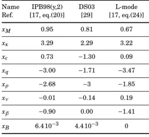
energy confinement time in dimensionless – also called “physics” – variables: ωcτE= e mp ¡CSLCαIICαtrP ¢1/(1+αP) λxρ ρ λνxνλxββ MxMκxκεxεqxq × BxBρxρ ∗ν xν ∗βxβ (24) with xM= (5αM+ 3αR+ 3αI+ 4αP− αn− 5)/5(1 + αP), xκ = (ακ+ αP)/(1 + αP), xε = (2αε+ αI− 3αR− 5αP+
2αn)/2(1 + αP), xq= (−4αI+ αR+ 3αP− 2αn)/5(1 + αP),
xρ= 2(−3αR−3αI−9αP+αn)/5(1+αP), xν= (−αR−αI−
3αP+2αn)/5(1+αP), xβ= (αR+αI+8αP+3αn)/5(1+αP)
and xB = (5 + 5αB− 4αR+ αI+ 3αP+ 8αn)/5(1 + αP).
Kadomtsev constraint imposes xB = 0. The zero-β
scaling further imposes xβ = 0. This constraint is well fulfilled by the scaling proposed in [29], where xβ= 4.4 10−3. The dimensionless coefficients associated
to the scaling laws detailed in Table 1 are given in Table 4. The last line shows that all three scaling laws fulfill Kadomtsev constraint. Interestingly, also notice that the newly proposed DS03 scaling law for ELMy H-mode plasmas predicts an opposite trend ofτE
with respect to the aspect ratio: there,τE is expected
to significantly increase with the aspect ratio, while the former IPB98(y,2) scaling predicts the opposite. This uncertainty reflects the lack of machines with sufficiently differentε values, and the likely bias which
exists for compact tokamaks, which usually operate at larger βN values than more conventional tokamaks.
Forthcoming data from the WEST tokamak, which should operate at large aspect ratioε−1∼ 5, will likely
help alleviating the uncertainty [1]. The impact of the aspect ratio on the dimensioning of DEMO is discussed in section 3.5, in the light of the inverse trend of the two scaling laws.
It also appears that, because of the effect of the coefficients, certain exponents of the engineering vari-ables play a more critical role than others, in the sense that a weak modification of their value translates into significant changes of the exponents of dimensionless variables (see also [15] on this issue). For instance, if the uncertainty onαP is of the order of ±5% (and
mod-ifyingαn by less than ±3% to preserve Kadomtsev
con-straint), then xρ and xβare modified by about −4% / + 9% and +29% /−56% respectively in the IPB98(y,2) scal-ing law (xρchanges by −2% / + 3% while xβis no longer
vanishing, ranging from +0.08 to −0.08 in the DS03 scaling law). Since xρ and xβsignificantly impact the dimensioning of tokamaks – as discussed below, such sensitivities advocate for refined accuracy with respect to the determination of these scaling exponents.
The objective here is to understand how the ma-jor radius scales with the scaling exponents xρ, xνand xβof the dimensionless variablesρ∗,ν∗andβ,
respec-tively. Indeed, working with dimensionless variables allows one to explore the impact of modified scaling ex-ponents, since each can be changed independently with-out affecting the physical consistency of the data. Pre-scribing B in (16-17) allows one to express R andβNas
functions of known variables, i.e. of (Q,Pbfus, nN, B, ...).
Hereafter, the ITER target values are considered (cf. Table 2). In particular, equation (17) can be rewritten
Table 4. Coefficients of a the scaling laws forτEdiscussed in Table 1 when expressed in dimensionless variables.
Name IPB98(y,2) DS03 L-mode Ref. [17, eq.(20)] [29] [17, eq.(24)]
xM 0.95 0.81 0.67 xκ 3.29 2.29 3.22 x² 0.73 −1.30 0.09 xq −3.00 −1.71 −3.47 xρ −2.68 −3 −1.85 xν −0.01 −0.14 0.19 xβ −0.90 0.00 −1.41 xB 6.4 10−3 4.4 10−3 0 as follows: R = µ Q γrad(1 + Q/λ) ¶`Q C trC`nn CSLC`IqC1/2f us × bP`P fusM−αMκ1/2−ακε`εq`qnb `n NB`B o`R (25) where`Q= 5/σ, `q= −αR+ 5(−3xρ+ 10xν− 3xβ)/σ, `n= 5(xρ/2−3xν)/σ, `P= (σ−10)/2σ, `ε= 2αR−αε+5(9xρ/2− 12xν+ 5xβ+ 1)/σ, `B = 5(3xρ/2 − 3xν+ 2xβ+ 1)/σ and `R= 2σ/[5(−5xρ/2 + 2xν− 3xβ− 3)] with σ = 5(1 − xρ/2 + 2xν− xβ).
Keeping the magnetic field constant at B = 5.3T and varying xρ from −3 to −2 – possibly mimicking the transition from gyroBohm to Bohm transport – it is found that the major radius increases from 5.3 m to 10.5 m for the IPB98(y,2) scaling law (and from 4.8 m to 22.7 m for the DS03 scaling law). Theρ∗parameter
almost scales like 1/R in this operation. The smaller size which is required at xρ = −3 to achieve given performance is a consequence of the better confinement which characterizes gyroBohm transport regimes.
The exponent xβ ofβ has been varied from −1.5 to 0. In this case, the major radius decreases from 6.9 m to 4.3 m for the IPB98(y,2) scaling law (and from 7.9 m to 4.8 m for the DS03 scaling law). The issue regarding the β dependence of the scaling law of the energy confinement time then appears as extremely important for the dimensioning of tokamaks.
Conversely, when varied from −0.2 to +0.2 (still at constant B = 5.3T), the xν scaling coefficient weakly
affects the size of the machine (by less than 3% and less than 19% in this range for the IPB98(y,2) and DS03 scaling laws, respectively).
3.5. Discussion regarding DEMO
Conversely to ITER, DEMO specifications are not fully settled yet [34]. Yet, significant progress have been
Table 5. Typical DEMO parameters considered in the paper. q ε−1 κ δ n N 3.2 3.1 1.59 0.33 1.2 fα M fp θi γrad 0.10 2.67 1.5 1/1.1 0.56
Table 6. Numerical values of the coefficients introduced in section 2. Cn CI Cβ Ctr Cf us
3.183 11.873 0.732 0.086 1.30 10−3
made [12], putting much emphasis on the impact of current uncertainties on the strategical choices [4, 3]. For the purpose of our analysis, we will hereafter prescribe a certain number of parameters within the right range of magnitude corresponding to the DEMO1 design (cf. [32, Table 1]). Especially, one targets Q = 40 and bPfus = 2.037 GW, hence requiring about 51 MW of auxiliary heating. The remaining parameters which are considered hereafter are detailed in Table 5. The numerical values of the corresponding coefficients introduced in section 2 are given in Table 6. Several parameters are changed as compared to ITER. The aspect ratio, the edge safety factor and elongation are about the same. The fraction of α particles
is increased up to 10% to account for the expected larger amount of fusion reactions. The temperature peaking factor is increased at 1.5 for the same reason (this would correspond to νT ≈ 1.41 with the profile
shapes discussed in section 3.1). Also, the radiation fraction is increased (lower γrad = 0.56) to account
for larger Bremsstrahlung losses and the need to radiate a significant amount of power at the edge via impurity injection §. Finally, an additional coefficient is usually introduced: H represents the ratio between the expected energy confinement time and the one deduced from the considered scaling law. H > 1 for IPB98(y,2) or DS03 scaling laws means better confinement than standard H-mode. In line with published data, we have taken H = 1.1
The solution triplet (R, B,βN) is plotted on figure
5 when considering the two scaling laws for ELMy H-modes. Again, we recall that all other parameters but
§ Notice that, according to [32], the total radiation power is expected to reach about 66% of the total heating power in DEMO1: (1− γrad)=Prad/PS ce≈306/462 if neglecting the Ohmic heating power. However, as discussed in [24], only a fraction of the total radiated power should be subtracted to the source heating power. This additional “user defined” parameter aims at accounting for the fact that scenarios with high core radiation have been explicitly excluded from current scaling laws, as pointed out in [35]. The retained value 0.56 of the coefficient is consistent with current estimates for DEMO1.
Figure 5. Same as figure 1 for DEMO specifications (here, Ptris
calculated by assuming that 66% of the heating source is radiated, cf. text). Both IPB98(y,2) and DS03 scaling laws are considered.
(R, B,βN) are fixed and given in table 5. It readily
appears that they operate in different parameter ranges with respect toβN: while the IPB98(y,2) scaling
law finds solutions around βN ∼ 2.2, DS03 predicts
solutions closer to βN ∼ 3.8. Such large values of
βN may actually reveal difficult to achieve. Indeed,
deleterious ideal MHD instabilities are expected to develop above βN,crit ≈ 3 [30]. Also, the growth
of resistive wall modes (RWM) can constitute the primary limitation toβN in advanced tokamak plasma
experiments. Although possible optimizations (such as plasma shaping) can increase the achievable βN,
and feedback loops are efficiently developed to control RWM (see e.g. [14]), such scenarios are all the more challenging in a reactor, which should essentially aim at zero disruption during its lifetime. Yet, apart from βN, both scaling laws predict solutions in the
same range of parameters regarding all other variables. Considering RDEMO= 9.1 m [32], critical variables are
listed in Table 7 for both scaling laws. The relative differences reach about 27% for the temperature, larger for DS03, density and plasma current, both smaller for DS03. This latter point, and the fact also that B is reduced, make the predictions relying on DS03 more favorable. Computing the thermal heat power crossing the separatrix is not an easy task. Indeed, it would require subtracting the entire radiated power inside the separatrix, which is larger than (1 − γrad)PS ce as
discussed above. Considering that it reaches about 66% of the heating source as in [32], one finds that this power is roughly Ptr≈157.5 MW in both cases. Its ratio
with respect to the L-H power threshold, Ptr/PL−H, is
plotted on figure 5 (dashed-dotted lines). At RDEMO=
Table 7. DEMO characteristic parameters when using IPB98(y,2) and DS03 scaling laws forτE.
IPB98(y,2) DS03 R[m] 9.1 9.1 B[T] 5.6 4.2 βN 2.2 3.8 b n[1019m−3] 8.7 6.6 b T[keV ] 12.9 17.0 b Ip [M A] 19.6 14.9 τE [s] 4.6 4.6
Conversely the ratio marginally reaches unity for IPB98(y,2). This may have significant consequences regarding technological constraints. Indeed, one would expect about 27.5 MW.m−2 on the divertor target
plates (with the same assumptions as those for ITER, section 3.2), implying the need for additional radiation at the edge to remain below the upper bound of 10 MW.m−2. Then, given the absence of margin
regarding the L-H power threshold, it may actually reveal impossible to fulfill this constraint while still being in H-mode if the IPB98(y,2) scaling law holds (unless relying on the possible hysteresis of the L-H power threshold [6]).
Arguing that DEMO cannot face any ELM so as to ensure the safety of its divertor, one might wonder what dimensioning one would expect if operating in L-mode. Using the L-mode scaling law whose coefficients are re-called in Table 1, the model gives the following possible choice for the triplet (R, B,βN): R ≈ 14m, B ≈ 8.9T and
βN≈ 0.46, leading to a heat power crossing the
sepa-ratrix (same assumption as above) of ∼ 157.5MW be-low the empirical L-H threshold of PL−H∼ 535 MW. In this case, the required plasma current would be about 47.9 MA. In the frame of our simple model, operating DEMO in L-mode looks hardly achievable.
As stated in [32], the aspect ratio A = R/a is a central design parameter in many aspects, including plasma stability issues, disruption forces, tritium breeding, maintenance and cost, among others. Yet, there is some freedom in its choice, although increased stability of divertor detachment regimes – as required to access strong dissipation of the parallel heat exhaust via efficient radiation – might favor low aspect ratio machines [21]. In this framework, and because of the opposite scaling of τE with ε when expressed in
dimensionless variables (cf. section 3.4), we have explored the sensitivity of the solutions with respect to A. For this purpose, fixed values ofβNare considered:
βN= 2.2 for the IPB98(y,2) scaling law, and βN= 3.8 for
the DS03 scaling law. The different values account for the different operational spaces for these two scaling laws (cf. figure 5). The range of variation of A is borrowed from [32]. The results are displayed on figure 6. It readily appears that the variations with A of both solutions R and B are opposite for the two scaling laws. Indeed, while R decreases with A if IPB98(y,2) holds, it increases with A if DS03 holds. The opposite is true for B. Besides, the range of variation of R is much larger for DS03 than for IPB98(y,2). Finally, one notices that such scenarios would marginally operate in H-mode for the IPB98(y,2) case (Ptr/PL−H ranges from
1.08 at A = 2.6 down to 0.90 at A = 3.6 in this case), while the H-mode threshold is well overcome for the DS03 case (Ptr/PL−H ≈ 1.67 at A = 2.6 and ≈ 1.34 at
A = 3.6).
As obvious from this analysis, transport issues, namely scaling laws, may have a strong impact on the final choice of the optimal aspect ratio for DEMO. The two scaling laws which we have considered, although exhibiting roughly the same variance of experimental data (of the order of 16%), have opposite signs for the dimensionless scaling exponent of A = ε−1(see table 4).
As a result, they lead to opposite trends for R and B when A is varied at constant βN. Consolidating the
sign of this exponent, on the basis of both first principle simulations and of novel experiments, appears highly desirable.
Figure 6. R (red) and B (blue) solutions for DEMO when varying the aspect ratio R/a at fixedβN:βN=2.2 for the IPB98(y,2) scaling law (plain lines), andβN=3.8 for the DS03 one (dashed lines). The ratio Ptr/PL−His also plotted, in the same way as for figure 5.
4. Conclusion
A simple (mostly 0-dimensional) model is proposed for the dimensioning of tokamaks. Most of the coefficients
are calculated in a comprehensive way. Given target parameters in terms of fusion gain Q and fusion power Pfus, and further prescribing the geometry, the model allows one to find suitable quadruplets (R, B, nN,βN),
i.e. the major radius, the magnetic field, the fraction of Greenwald density and the normalizedβ. To proceed,
three scaling laws for the energy confinement time have been considered in a systematic way, valid either for L-mode (only used for DEMO design here) or for H-mode plasma regimes. When using the IPB98(y,2) scaling law, ITER typical parameters are recovered when targeting Q = 10 and Pfus= 500 MW. It is shown that some differences are obtained when using the recently published DS03 new scaling law, although the orders of magnitude are in the same range. Noticeably, the required magnetic field B is smaller, whileβN is
larger.
Also, it is shown how the uncertainty on the exponents of the τE scaling law, both in terms of
engineering and dimensionless variables, can impact dramatically the size of the machine. Some of the most critical exponents in that respect are highlighted, pointing towards the already noticed critical role of the
ρ∗ exponent. Finally, it is shown that a DEMO-like
machine should operate at largerβNand lower plasma
current if the DS03 scaling law holds, as compared to predictions using the IPB98(y,2) scaling. However, the relevance of these largeβN plasmas for a reactor may
be questioned due to their inherent larger sensitivity to MHD instabilities, and the consequent higher risk of disruptions. Most importantly, the opposite scaling of both scaling laws with respect to the aspect ratio leads to radical differences regarding the optimal choice of this critical parameter. Especially, the DS03 law predicts that similar performance can be achieved at lower R (and slightly larger B) when reducing R/a.
Acknowledgments
The authors wish to acknowledge fruitful discussions with C. Reux regarding system codes in general and SYCOMORE in particular. The positive and construc-tive feedback received from the master students who have participated in the dimensioning project at CEA-Cadarache, France, in February 2019, is also greatly appreciated. Finally, we would like to acknowledge the relevant comments and useful suggestions of an anony-mous referee.
Appendix A. Fusion power and momentum conservation
Deuterium-tritium fusion reactions result from inelas-tic collisions, for which momentum is conserved, not en-ergy. The total kinetic energy release for a single
re-action amounts to Eb0= 17.59MeV. So as to evaluate
the fraction of energy carried out by the neutron, rel-ativistic corrections have to be taken into account. The method is detailed below.
Let’s admit that it is sufficient to account for relativistic corrections for neutrons (their velocity reaches approximately 0.17 c, with c the speed of light), while α particles can be treated within the classical
framework (their velocity is about 0.04 c). Momentum conservation then reads:
mnγnvn= mαvα (A.1)
with γn = (1 − v2n/c2)−1/2 the Lorentz factor for the
neutrons. In the limit (vn/c)2¿ 1, γn can be Taylor
expanded, so that (A.1) can be recast as follows: u[1 + (²/2) u2] = 1, with u= v. n/(µvα), µ= m. α/mn and
² = µ(v. α/c). Since ² ¿ 1, it is sufficient to look for
perturbative solutions of the form: u = u0+ u1 with
u1¿ u0. The approximate solution then reads: vn'
µvα(1 − ²2/2). Injecting this expression in the kinetic
energy of the neutron Enleads to:
En= mnc2(γn− 1) ≈ mn 2 v 2 n · 1 +3v 2 n 4c2 ¸ ≈ µ Eα µ 1 −² 2 4 ¶
The kinetic energy of the α particle Eα can then be
expressed as a function of the total energy E0 (E0=
Eα+ En):
E2α−2(1 + µ)
µ2 En0Eα+
2
µ2En0E0= 0 (A.2)
with En0= mnc2 the mass energy of the neutron and
using the relation²2
= 2µ Eα/En0. The only acceptable
solution is: Eα=1 + µ µ2 Ã 1 − s 1 − 2µ 2 (1 + µ)2 E0 En0 ! En0 (A.3)
At leading order in E0/En0¿ 1, this solution simply
reduces to Eα ≈ E0/(1 + µ) ≈ E0/5. Notice that µ 6=
4. Indeed, the mass of the α particle is slightly less than the sum of its components (actually, this mass difference ∆m ≈ 0.0187 mp is the one which leads to
the energy release of the D-T fusion reaction E0 =
∆m c2). The masses can be found in reference [33]. In particular, mn≈ (1 + 0.001378) mpandµ= m. α/mn≈
(1 − 0.027404) mp/mn ≈ 3.967. With these data, one
finally obtains E0/Eα≈ 4.94 and bEα≈ 3.56 MeV.
Appendix B. Fraction ofα particles
The total number Nα = nαVt of α particles in the
confined plasma can be estimated from the following balance equation:
Nα
τα = Sα+ Rα
Nα
τα (B.1)
The left hand side accounts for the radial transport due to both turbulence and collisions, with the
characteristic timeτα. The right hand side represents
the sources: the volumetric source due to D-T fusion reactions, and the wall recycling characterized by the coefficient 0 ≤ Rα≤ 1. Rα accounts for the pumping
efficiency of the α particle pumps installed in the
divertor. The effective confinement time of the α
particles then readsτ∗
α= τα/(1 − Rα).
Sα reads as follows (for T in the range 10.3-18.5 keV): Sα= nDNT〈σv〉Vt≈ 1.18 1014 4 (nbT)b 2V t (B.2)
Without any obvious estimate for τ∗
α, it is usually
assumed to scale with τE: τ∗α ∼ CατE, with typical
values in the range Cα < 5 − 10 in H-mode [22, section 2.3] (particle confinement times are usually larger than the one of energy because the later has several transport channels (convection and conduction) whereas particle transport is due to convection only).
The fraction ofα particles then simply reads: fα=. nα n ≈ 1.18 10−5Cα 4 nbTb 2τ E (B.3)
Taking ITER parameters given in section 3.2 and Cα= 4.65, one finds fα≈ 3.5%, which is the fraction we have considered for ITER. The fraction considered for DEMO fα= 10% is also consistent with the values obtained for density, temperature and confinement time, with Cα≈ 4.
[1] J. Bucalossi, A. Argouarch, V. Basiuk, O. Baulaigue, P. Bayetti, M. Bécoulet, B. Bertrand, S. Brémond, P. Cara, M. Chantant, Y. Corre, X. Courtois, L. Doceul, A. Ekedahl, F. Faisse, M. Firdaouss, J. Garcia, L. Gargiulo, C. Gil, C. Grisolia, J.Gunn, S.Hacquin, P.Hertout, G.Huysmans, F.Imbeaux, G.Jiolat, M.Joanny, L.Jourd’heuil, M.Jouve, A.Kukushkin, M.Lipa, S.Lisgo, T.Loarer, P.Maget, R.Magne, Y.Marandet, A.Martinez, D.Mazon, O.Meyer, M.Missirlian, P.Monier-Garbet, P.Moreau, E.Nardon, S.Panayotis, B.Pégourié, R.A.Pitts, C.Portafaix, M.Richou, R.Sabot, A.Saille, F.Saint-Laurent, F.Samaille, A.Simonin, and E.Tsitronea. Feasibility study of an actively cooled tungsten divertor in Tore Supra for ITER technology testing. Fusion Engineering and Design, 86:684–688, 2011.
[2] E. Caschera, G. Dif-Pradalier, and P. Ghendrih. Scaling law of the energy confinement time in global flux driven gyrokinetic simulations. private communication, 2019.
[3] M. Coleman, Y. Hörstensmeyer, and F. Cismondi. DEMO tritium fuel cycle: performance, parameter explorations, and design space constraints. Fusion Engineering and Design, 141:79–90, 2019.
[4] M. Coleman, F. Maviglia, C. Bachmann, J. Anthony, G. Federici, M. Shannon, and R. Wenninger. On the EU approach for DEMO architecture exploration and dealing with uncertain-ties. Fusion Engineering and Design, 109-111:1158–1162, 2016.
[5] J.W. Connor and J.B. Taylor. Scaling laws for plasma confinement. Nucl. Fusion, 17(5):1047, 1977.
[6] J.W. Connor and H.R. Wilson. A review of theories of the L-H transition. Plasma Phys. Control. Fusion, 42:R1–R74, 2000. [7] J.P. Christiansen J.G. Cordey, O.J.W.F. Kardaun, and K.
Thom-sen. Application of plasma physics constraints to confine-ment data. Nucl. Fusion, 31(5):2117, 1991.
[8] Collection du Commissariat à l’énergie atomique. La fusion thermonucléaire contrôlée par confinement magnétique. Mas-son, Série Scientifique, 1987.
[9] J.-L. Duchateau, P. Hertout, and J. Johner. Discussion About the Size of a Future Fusion Demonstration Reactor: The Impact of the Toroidal Magnetic Field. IEEE Transactions on Applied Superconductivity, 17:1342, 2007.
[10] J.-L. Duchateau, P. Hertout, B. Saoutic, J.-F. Artaud, L. Zani, and C. Reux. Conceptual integrated approach for the magnet system of a tokamak reactor. Fusion Engineering and Design, 89:2606–2620, 2014.
[11] S. Entler, J. Horacek, T. Dlouhy, and V. Dostal. Approximation of the economy of fusion energy. Energy, 152:489–497, 2018. [12] G. Federici, W. Biel, M.R. Gilbert, R. Kemp, N. Taylor, and R. Wenninger. European DEMO design strategy and consequences for materials. Nuclear Fusion, 57:092002, 2017.
[13] J.P. Freidberg. Plasma Physics and Fusion Energy, volume 1. Cambridge University Press, 2007.
[14] A.M. Garofalo, M.S. Chub, E.D. Fredrickson, M. Gryaznevich, T.H. Jensen, L.C. Johnson, R.J. La Haye, G.A. Navratil, M. Okabayashi, J.T. Scoville, E.J. Strait, A.D. Turnbull, and DIII-D Team. Resistive wall mode dynamics and active feedback control in DIII-D. Nuclear Fusion, 41(9):1171, 2001. [15] Ph. Ghendrih, G. Dif-Pradalier, C. Norscini, T. Cartier-Michaud, D. Estève, X. Garbet, V. Grandgirard, G. Latu, C. Passeron, and Y. Sarazin. Self organisation of plasma turbulence: impact on radial correlation lengths. Journal of Physics: Conference Series, 561:012008, 2014.
[16] M. Greenwald. Density limits in toroidal plasmas. Plasma Physics and Controlled Fusion, 44(8):201, 8 2002.
[17] ITER Physics Basis Editors ITER Physics Basis Expert Groups on Confinement and Transport and Confinement Modelling and Database. Chapter 2: Plasma confinement and transport. Nuclear Fusion, 39(12):2175–2249, 12 1999. [18] J. Johner. HELIOS: a zero-dimensional tool for next step and
reactor studies. Fusion Science and Technology, 59:308–349, 2 2011.
[19] B.B. Kadomtsev. Tokamaks and dimensional analysis. Sov. J. Plasma Phys., 1:295, 07 1975.
[20] M. Kovari, R. Kemp, H. Lux, P. Knight, J. Morris, and D.J. Ward. “PROCESS”: A systems code for fusion power plants - Part1: Physics. Fusion Engineering and Design, 89:3054–3069, 07 2014.
[21] B. Lipschultz, F. I. Parra, and I. H. Hutchinson. Sensitivity of detachment extent to magnetic configuration and external parameters. Nuclear Fusion, 56:056007, 2016.
[22] A. Loarte, B. Lipschultz, A.S. Kukushkin, G.F. Matthews, P.C. Stangeby, N. Asakura, G.F. Counsell, G. Federici, A. Kallenbach, K. Krieger, A. Mahdavi, V. Philipps, D. Reiter, J. Roth, J. Strachan, D. Whyte, R. Doerner, T. Eich, W. Fundamenski, A. Herrmann, M. Fenstermacher, P. Ghendrih, M. Groth, A. Kirschner, S. Konoshima, B. LaBombard, P. Lang, A.W. Leonard, P. Monier-Garbet, R. Neu, H. Pacher, B. Pégourié, R.A. Pitts, S. Takamura, J. Terry, E. Tsitrone, the ITPA Scrape-off Layer, and Divertor Physics Topical Group. Progress in the ITER Physics Basis Chapter 4: Power and particle control. Nuclear Fusion, 47:S203–S263, 2007.
[23] T. Luce. Application of dimensionless parameter scaling tech-niques to the design and interpretation of magnetic fusion ex-periments. Plasma Phys. Control. Fusion, 50:043001, 2008. [24] H. Lux, R. Kemp, D.J. Ward, and M. Sertoli. Impurity radiation
in DEMO systems modelling. Fusion Engineering and Design, 101:42, 2015.
[25] Y.R. Martin, T. Takizuka, and ITPA CDBM H mode Threshold Database Working Group. Power requirement for accessing the H-mode in ITER. Journal of Physics: Conference Series, 123:01203, 2008.
J. Bucalossi, G. Ciraolo, J.-L. Duchateau, C. Fausser, D. Galassi, P. Hertout, J.-C. Jaboulay, A. Li-Puma, B. Saoutic, L. Zani, and ITM-TF Contributors. DEMO reactor design using the new modular system code SYCOMORE. Nucl. Fusion, 55:073011, 2015.
[27] C. Reux, S. Kahn, L. Zani, B. Pégourié, N. Piot, M. Owsiak, G. Aiello, J.-F. Artaud, A. Boutry, S. Dardour, L. Di Gallo, J.-L. Duchateau, D. Galassi, F. Imbeaux, J.-C. Jaboulay, P. Magaud, J. Said, B. Saoutic, and P. Sardain. DEMO design using the SYCOMORE system code: Influence of technological constraints on the reactor performances. Fusion Engineering and Design, 136:1572–1576, 2018. [28] M. Siccinio, E. Fable, C. Angioni, S. Saarelma, A. Scarabosio,
and H. Zohm. Impact of an integrated core/SOL description on the R and BT optimization of tokamak fusion reactors. Nuclear Fusion, 58:016032, 2018.
[29] A.C.C. Sips, J. Schweinzer, T.C. Luce, S. Wolfe, H. Urano, J. Hobirk, S. Ide, E. Joffrin, C. Kessel, S.H. Kim, P. Lomas, I. Nunes, T. Pütterich, F. Rimini, W.M. Solomon, J. Stober, F. Turco, P.C. de Vries, JET Contributors, The ASDEX Upgrade team, The DIII-D team, The C-Mod team, The JT-60U team, and ITPA-IOS TG members and experts. Assessment of the baseline scenario at q95∼3 for ITER.
Nuclear Fusion, 58:126010, 2018.
[30] E.J. Strait. Stability of high beta tokamak plasmas. Physics of Plasmas, 1:1415, 1994.
[31] F. Troyon, R. Gruber, H. Saurenmann, S. Semenzato, and S. Succi. MHD-Limits to Plasma Confinement. Plasma Physics and Controlled Fusion, 26(1A):209–215, 1 1984. [32] R. Wenninger, R. Kembleton, C. Bachmann, W. Biel, T.
Bol-zonell, S. Ciattaglia, F. Cismondi, M. Coleman, A.J.H. Donné, T. Eich, E. Fable, G. Federici, T. Franke, H. Lux, F. Maviglia, B. Meszaros, T. Pütterich, S. Saarelma, A. Snickers, F. Vil-lone, P. Vincenzi, D. Wolff, and H. Zohm. The physics and technology basis entering European system code studies for DEMO. Nuclear Fusion, 57:016011, 2017.
[33] J. Wesson. Tokamaks. Oxford University Press, 3rd edition, 2004.
[34] H. Zohm. On the minimum size of DEMO. Fusion Science and Technology, 58:613, 2010.
[35] H. Zohm, C. Angioni, E. Fable, G. Federici, G. Gantenbein, T. Hartmann, K.Lackner, E. Poli, L. Porte, O. Sauter, G. Tardini, D. Ward, and M. Wischmeier. On the physics guidelines for a tokamak DEMO. Nuclear Fusion, 53:073019, 2013.
[36] H. Zohm, F. Träuble, W. Biel, E. Fable, R. Kemp, H. Lux, M. Siccinio, and R. Wenninger. A stepladder approach to a tokamak fusion power plant. Nuclear Fusion, 57:086002, 2017.
![Table 1. Coefficients of a few scaling laws for τ E (the α R exponent of the L-mode scaling law has been modified so that the scaling law fulfills Kadomtsev constraint, as suggested in [17, p.2206]).](https://thumb-eu.123doks.com/thumbv2/123doknet/12958543.376566/7.918.91.333.152.400/coefficients-scaling-exponent-modified-fulfills-kadomtsev-constraint-suggested.webp)
![Figure 3. Same as figure 1 when using the DS03 scaling law [29].](https://thumb-eu.123doks.com/thumbv2/123doknet/12958543.376566/9.918.478.800.459.736/figure-figure-using-ds-scaling-law.webp)
![Figure 4. Same as figure 2 when using the DS03 scaling law [29].](https://thumb-eu.123doks.com/thumbv2/123doknet/12958543.376566/10.918.100.427.87.365/figure-figure-using-ds-scaling-law.webp)