HAL Id: cea-02873058
https://hal-cea.archives-ouvertes.fr/cea-02873058
Submitted on 18 Jun 2020
HAL is a multi-disciplinary open access archive for the deposit and dissemination of sci-entific research documents, whether they are pub-lished or not. The documents may come from teaching and research institutions in France or abroad, or from public or private research centers.
L’archive ouverte pluridisciplinaire HAL, est destinée au dépôt et à la diffusion de documents scientifiques de niveau recherche, publiés ou non, émanant des établissements d’enseignement et de recherche français ou étrangers, des laboratoires publics ou privés.
L. Ferry, Daniel Parrat, C. Gonnier, C. Blandin, J. Estrade, Y Weiss, A Sasson
To cite this version:
L. Ferry, Daniel Parrat, C. Gonnier, C. Blandin, J. Estrade, et al.. LORELEI: A future Test Device for LOCA Experiments in the JHR. IGOR 2014 / The 16th International Group Operating Research Reactors Conference, IAEA, Nov 2014, San Carlos de Bariloche, Argentina. �cea-02873058�
1
LORELEI: A future Test Device for LOCA Experiments in the JHR
L. Ferry1, D. Parrat2, C. Gonnier1, C. Blandin1, J. Estrade1, Y. Weiss3, A. Sasson3, & al1) CEA, DEN, DER, CEA Cadarache, Building 1222, F-13108 Saint Paul lez Durance, France
2) CEA, DEN, DEC, CEA Cadarache, Building 151, F-13108 Saint Paul lez Durance, France 3) Rotem Industries LTD, Mishor Yamin, D.N Arava 86800 Israel
Corresponding author: [email protected]
Abstract. The Jules Horowitz Reactor (JHR) is a high performance Material Testing Reactor (MTR) under construction in southern France (CEA Cadarache). JHR will host a set of fuel and material test facilities for the nuclear industry or other organizations. In the safety studies domain, the LORELEI (Light water One Rod Equipment for LOCA Experimental Investigations) test device is dedicated to the study of the thermal-mechanical behavior of a fuel rod and quantification of Fission Product (FP) and fissile material releases under Loss Of Coolant Accident (LOCA) type conditions. LORELEI will allow investigating ballooning and burst of the fuel cladding, clad corrosion phenomena (oxidation and hydriding), post quench behavior and FP release (for that aim, the device will be connected with water and gas sampling lines to the Fission Product Laboratory of the JHR). After a quick description of the JHR, this paper presents the main objectives of the LORELEI test device, its main technical characteristics and its experimental protocol.
1. Introduction
The Jules Horowitz Reactor (JHR) is a Material Testing Reactor (MTR) under construction at the CEA/Cadarache (France) and will be an important international user facility for R&D in support to the nuclear industry, research organizations, regulatory bodies and Technical Support Organization (TSO), and academic institutions [2], [3].
CEA is developing a set of test devices aiming at testing materials and fuels under irradiation [1]. More specifically, in the safety studies domain, CEA plans to propose a dedicated LOCA-type (Loss of Coolant Accident) test device, so-called LORELEI (“Light water One Rod Equipment for LOCA Experimental Investigations”), to its future customers. Such a family of experiments in the JHR will be devoted in priority to understand mechanisms governing the fuel sample behavior during a LOCA (in particular at high burn-up), to quantify the radionuclide released fraction whatever the type of their chemical form (gaseous, volatile, semi- and non-volatile, and fissile material if any) and to supply data and validate safety codes. The design and manufacturing of the test device are made in collaboration with the Israel Atomic Energy Commission (IAEC).
This paper describes the main objectives of LORELEI and presents an experimental sequence designed to simulate a real loss of coolant accident which could occur in a power reactor. It also describes the main features of the JHR and the LORELEI test facility itself.
The LORELEI facility is expected to be operational just after the JHR commissioning.
2. Main features of the JHR facility
This facility is based on a 100 MWth pool reactor compact core cooled by a slightly pressurized primary circuit. The core tank is located in the reactor pool. A typical reactor cycle is expected to last 25 days, and CEA targets to operate the reactor 10 cycles per year.
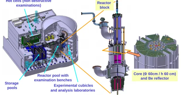
The nuclear facility comprises a reactor building with all equipment dedicated to the reactor and experimental devices and an auxiliary building dedicated to tasks in support to reactor and experimental devices operation (see Fig 1).
2
The reactor building is designed to provide the largest experimental capacity possible with the largest flexibility. One half of this building is dedicated to the implementation of equipment in support to in-pile irradiations. This corresponds to 700 m2 over 3 floors for implementation of experimental cubicles and 490 m2 over 3 floors for instrumentation and control equipment.
Fig 1. Views of the JHR facility and the reactor core
3. Objectives of the LORELEI test device
These objectives are to focus on the thermal-mechanical behavior of the rod and to quantify fission product releases. It will not be designed to reproduce specific thermal-hydraulical aspects such as blow-down, dry-out or reflooding phases occurring during a real LOCA sequence.
The LORELEI test device will mainly contribute to characterize new cladding materials, optimized or new fuel materials, new fuel assemblies design, new fuel management strategies (high burn-up, high duty) and the corresponding FP releases in LOCA situation. This facility will be also devoted to investigate specific phenomena such as possible fuel relocation (within the rod and out-of the rod), impact of grids on fuel relocation, etc. The experimental fuel rod itself shall have a realistic internal gaseous energetic load (i.e. plenum volume and filling pressure related to the fissile stack length).
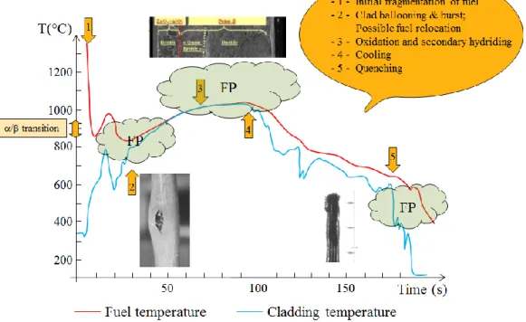
Moreover, and beyond LOCA issues, following the Fukushima events, there is an increasing international interest to evaluate some alternative cladding materials which could give some additional margins upon LOCA conditions and beyond for LWRs. Specific tests have thus to be defined to address this issue in the future, and LORELEI will comply with this new need. During a typical “large breach” LOCA sequence (such as LORELEI sequence), several phenomena can be observed on a fuel rod (see Fig 2):
The reactor shutdown initially causes a dramatic drop of the fuel pellet central temperature and a flattening of the radial temperature profile due to a quasi-isothermal behavior (very bad thermal exchange with the primary steam).
The rise in temperature and the pressure decrease in the primary circuit lead to the ballooning of the clad after phase transformation. This generally provokes the failure of the clad at a temperature ranging from 700 to 900°C. This failure is accompanied by a first burst release of fission product (mainly noble gases).
A large change in the fuel stack geometry can occur, with filling of the balloon with fuel grains,
Hot cells (non destructive examinations)
Experimental cubicles and analysis laboratories Reactor pool with
examination benches Core ( 60cm / h 60 cm) and Be reflector Storage pools Reactor block
3
A temperature equilibrium is reached at a value about 1000 to 1200°C, and a temperature plateau lasts a few tens of seconds with a very flat radial profile in the fuel pellet,
The cladding oxidation phase occurs significantly during this high temperature plateau, between 1000 and 1200°C, and leads to:
- The development of a supplementary oxide layer over a subjacent oxide layer with high oxygen content;
- The production of hydrogen. One part of it can interact with metal (hydriding);
- The resulting clad embrittlement; - Heat emission.
The cooling/quenching phase can lead to the brittle fracture of the clad by thermal shock if the corrosion thickness or the hydride local concentrations are large enough. This embrittlement, together with liquid water ingress in the balloon, is accompanied by a supplementary fission product and sometimes fuel fragmentation and actinides release.
Fig 2. Phases of the LOCA sequence
Such sequence is a strong challenge for a relevant assessment of phenomena:
The representative cladding creep-ballooning and burst and its resistance to rupture during or after the final quenching is an important issue. Dedicated on-line and/or post-LOCA transient thermal-mechanical tests together with deep microstructural & microchemical post-quenching characterization of the cladding materials have to be developed. The objective is to derive a physics based relationship between the actual cladding mechanical properties and its residual microstructure, during and/or after LOCA transient tests,
The chemical and mechanical interactions between the fuel pellet and the cladding tube is also an important issue and more studies have to be done to get better insights into the potential fuel relocalization and dispersal.
4
4. Device main characteristics 4.1. In-pile components
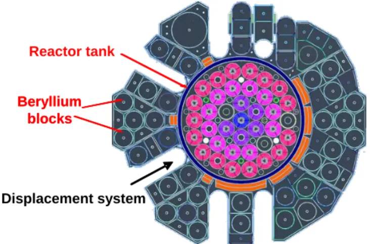
The in-pile part of the device will be installed in a water channel of the reflector (see Fig 3). The water channel will be equipped with a displacement system allowing a radial movement of about 45 cm. The power is therefore controlled by the distance between the sample and the core vessel. The progression of the displacement system will be limited by an adjustable mechanical stop block to prevent any movement towards the reactor beyond a certain distance, thereby limiting the power generated in the fuel rod.
The in-pile device is connected to a device holder which is fixed on the displacement system. An anti-fly off system will be positioned on the top of the device and fixed to the displacement system to prevent any vertical movement of the in-pile device which could follow some specific accidental sequences with a quick coolant circuit depressurization.
Fig 3. Location of the Lorelei test device in the reflector
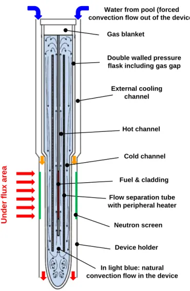
The in-pile device has been designed to work as a closed capsule where the fuel rod is cooled in natural convection with a single phase thermo-siphon circulating inside the device.
The device presents a change in diameter in the middle of its vertical axis (see Fig 4). The lower part of the device, with the smaller diameter, contains the fuel rod and is in the under neutron flux area. The upper part, with the bigger diameter, is above the neutron flux zone and plays the role of a heat exchanger where the power generated in the lower part is transferred to the cooling water surrounding the outer flask. This two diameters shape limits power generation volume in the under flux area and offers high heat transfer area in the upper part.
The in-pile device is bounded by a double flask made of stainless steel. The inner flask is a pressure flask designed to withstand the internal pressure while the outer flask is only a second envelope whose function is mainly to form a gas gap. This gap is filled with helium and plays the role of thermal insulation between the hot inner parts and the water of the pool surrounding the device. Monitoring the pressure in the gas gap will also be used to detect potential leakage in the flasks. The gas gap is thin in the upper part (0.5 mm), where no deformations are expected, to increase the heat transfer toward the pool. The gas gap is thicker in the lower part (1 mm) where mechanical structures are expected to bend because of azimuthal thermal gradient.
The fuel sample is held by a sample holder at the center of the device. A flow separation tube is installed in the flask, forming two concentric channels, a hot channel surrounding the fuel sample and a cold channel between the separator and the inner flask. Thanks to this separation, a thermosiphon can build up ensuring the cooling of the fuel rod during the re-irradiation phase before the LOCA transient starting. The flow field within the test device is complex due to the
Beryllium blocks Reactor tank Beryllium blocks Displacement system
5
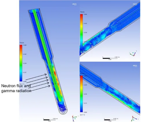
opposing forces -buoyancy forces and natural convection flow generated by the fuel power in the hot channel, opposed by buoyancy forces generated by non-uniform gamma power generated in the device structure. Fig 5 shows the results of a CFD numerical simulation of the conjugated turbulent natural convection and heat transfer in a 3D geometry [6].
The flow separator integrates a peripheral heater which is used to create adiabatic conditions for the fuel during the adiabatic heating phase.
The gap between the device holder and the outer flask forms a cooling channel where the water coming from the pool flows in forced convection using an independent on-board pump on the displacement system.
A neutron hafnium shield will be fixed on the inner side of the device holder and will be used to flatten the axial flux up to 40 cm height.
Fig 4. Thermosiphon flow during re-irradiation
Hot channel
Cold channel Double walled pressure flask including gas gap
Flow separation tube with peripheral heater
Fuel & cladding Gas blanket
External cooling channel
Water from pool (forced convection flow out of the device)
Un de r flux a re a Device holder Neutron screen
In light blue: natural convection flow in the device
6
Fig 5. Stream lines during the re-irradiation phase
Instrumentation will be implemented in order to monitor temperature and pressure in different parts of the device and at each step of the experimental sequence. The top of the fuel sample holder axial displacement will also be measured. Based on the axial displacement measurement and thermal expansion computations, an estimation of the specimen total elongation will be predicted. The implementation of such numerous components and sensors in a very limited space (needle geometry: more than 3 meters long vs 10 cm outer diameter) is an issue but the preliminary design [7] (see Fig 6) shows that it is possible to ensure all the required scientific objectives.
7
4.2. Components outside the reactor pool
The LORELEI test device will be connected to a devoted cubicle through under water hydraulical and electrical lines (see Fig 7). This out-of-pile equipment will be designed to insure the initial configuration of the loop, to control the emptying and reflooding phases.
The LORELEI test device will also be connected to the Fission Products laboratory (where all the contaminated fluids will be directed, analyzed and partly sampled at the end of the test) [5]. One sampling line, located at the bottom of the device will be used for water and one sampling line, at the top of the vessel, will be used for gas.
The LORELEI cubicle will also be used to store contaminated gases and liquids which have been sent through the FP laboratory. These fluids will be stored in different vessels depending on their contamination levels.
Fig 7. Schematic layout (within and outside the reactor pool)
5. LOCA sequence
The test device is filled with water and operated as a capsule in natural convection (single phase thermo-siphon) in order to re-irradiate the fuel sample. A volume of helium is located above the water level, as a gas blanket, and is pressurized to set the static pressure (about 70 bars). During this phase, fluids can be sampled to check the tightness of the cladding.
The device will be irradiated at low power for a few days in order to generate detectable short half-life fission products. This will lead to a possible non-representative inventory and distribution for some FPs but it will be possible to detect all the fission products even in the case of a high burn-up rod test. As an example, the detected activity (counting rate) of the short half-life 131I will be of the same amplitude than the long half-life 137Cs.
The nominal linear power of the re-irradiation will be about 30 W/cm (but the design is based on a linear power of 100 W/cm).
Then the main steps of the LOCA sequence itself are as follow (see Fig 8):
Underwater lines Pool penetration Highly contaminated gas Highly contaminated liquids Water supply Pressure supply Low contaminated gas + liquids Reactor pool Cubicle
8
Following dewatering (draining the water out of the device by injecting gas), the pressure inside the device will be limited to a few bars. Therefore, in order to avoid boiling in the device the water will be cooled down before emptying by moving the displacement device to back position. A small amount of water will remain at the bottom of the device in order to provide a saturated steam atmosphere during the dry phase sequence. The steam will be generated by an electrical heater located at the bottom of the flask. A debris catcher will also be fitted near the bottom of the device in order to retrieve fuel particles (if any) without hampering steam generation.
The temperature heat-up rate will be adjusted by controlling the position of the displacement system. It will range between 5 and 10°C/s up to cladding failure. The initial internal fuel sample pressure will be a test parameter that can be adjusted while preparing the specimen before every experiment, depending on the expected ballooning and burst conditions. In order to avoid peripheral temperature discrepancies and to insure adiabatic conditions, a peripheral electrical heater is implemented in the flow separator to compensate for peripheral differences in thermal insulation and thermal inertia. The azimuthal cladding temperature difference is expected to be less than 10°C.
The peripheral heater will be stopped after clad burst or when reaching 900°C in order to increase the apparent heat-losses of the rod and to avoid the steam - Zircaloy thermal escalation. The temperature heat-up will go on until reaching the high-temperature plateau. The high temperature plateau will be reached as fast as possible, without increasing the heating rate above its specified value during the adiabatic heating phase and with a minimum temperature overshoot.
The cladding temperature will be stabilized at a predefined value selected in the range [1000, 1300°C] by adapting the nuclear power in the experimental sample. In this phase the oxidation reaction will be studied and the duration of this phase will be set according to preliminary estimation of the amount of Zirconium that will be reacted. The maximum cladding temperature will be maintained below 1550°C under all conditions by safety actions, which will exclude the possibility of cladding and fuel melting.
At the end of the plateau, the cooling of the device will first rely on heat losses by moving the displacement device backward to reduce the nuclear power. The fuel will be cooled passively at a rate of -1 to -10°C/s.
The quenching phase will then be instigated by injecting cold water from the bottom of the device. It will include the loading of the fuel sample during the quenching and just after the quenching (tensile loading of about 200N, 500N max). The reflooding will be initiated when reaching a pre-defined cladding temperature between 800 and 1200°C. The internal pressure flask will be designed to resist the pressure peaks associated with this phase.
After quenching, it will be possible to operate in the long term (several hours or days) at low power in order to study the post-quench fuel behavior. The pressure in the device will be low, up to 10 bars and the linear power will be up to 5 W/cm. After test end, the device will be emptied: reflooding water then upper gas blanket will be transferred to the LORELEI cubicle thanks to liquid and gas sampling lines. These lines will be connected to the FP laboratory in order to quantify fission products and fuel particles releases through on-line fluid monitoring and delayed measurements on samples (radioactive and atoms countings).
9
Fig 8. Description of the LOCA sequence (LORELEI)
6. On-site post-irradiation investigations
The essential supports of some JHR analysis laboratories and on-site non-destructive examination benches have to be highlighted because they greatly contribute to the quality of the experimental process [4]:
A fission product laboratory for welcoming and measuring fluids (gas + steam blanket and liquid after quenching) in contact with the tested rod during and after the LOCA-type sequence, either on-line during the fluid transferring between the test section and the FP Laboratory. or after sampling. For this last item, the target is to maximize the number of measured radioactive isotopes by detecting short half-lives as low as about one hour (e.g. 87Kr, 76 min);
A chemistry laboratory, for delayed measurements on samples for counting stable and radioactive isotopes, or for preparing samples (e.g. partitioning) for a specific analysis (alpha spectrometry etc.);
High performance non-destructive examinations benches, based on photon imaging techniques: X-tomography by transmission and gamma scanning and tomography by emission will be coupled and implemented on the same underwater bench. The handling process has to be capable to welcome quickly and easily the irradiation device containing the degraded rod. The goal is first to obtain a precise image of the sample “as tested” (e.g. fuel stack fragmentation and delocalisation status) without later evolution or issues caused by a transportation and also to be able to set up the complete and quantitative balance of fission products in the in-pile test section: FP remaining in the rod, deposited on the device walls or concentrated at the bottom part. Our target is to be able to start the gamma scanning sequence roughly 12 hours after the end of the test (this delay includes fluid transfers).
At last, the sample, the sample-holder and the test section will be filled with a metallic alloy in JHR hot cell for protecting the sample status during the transportation to the hot cell laboratory. Then micro-analyses on fuel and cladding will be planned after cutting and recovering the sample. Nuclear power Cladding temperature Re -i rra di a ti o n Em pty ing
Heating up Cooling and
quenching phase Time Temperature Power Cladding burst
10
6. Conclusion
The aim of the LORELEI test device is to implement high quality LOCA-type sequences for testing new fuels and materials, for solving pending issues on LOCA phenomenology, and for improving experimental data range and accuracy for codes and models validation. Testing on ATF will be in the scope of this test device as well.
These targets will be reached thanks to the services offered by the JHR, a new MTR under construction in Southern France: highly instrumented irradiation facilities, modern analysis laboratories and on-site non-destructive examination stands allowing for instance high-performance gamma and X tomographies on a routine basis.
This document describes the LORELEI test device itself, one of the JHR fuel test devices [1], its main objectives and its main functions. Main technical specifications of the reference experimental protocol have been defined.
After a feasibility phase completed in 2013, the detailed design phase of the LORELEI facility in is progress. The beginning of manufacturing is planned early 2016.
7. Références
[1] C. Blandin, P. Roux, T. Dousson, L. Ferry, D. Parrat, C. Gonnier, “LWR fuel irradiation hosting systems in the Jules Horowitz reactor”, LWR Fuel Performance Meeting 2013, September 2013, 15-19, Charlotte, NC, USA.
[2] G. Bignan, J. Estrade, “The Jules Horowitz Reactor: a new high performances European MTR (Material Testing Reactor) with modern experimental capacities: toward an international user facility”, International Group on Research Reactors - IGORR 2013, October, 13-18, 2013, Daejeon, Korea.
[3] G. Bignan, J.C. Brachet, G. Ducros, C. Gonnier, D. Parrat, M. Tourasse, “The OECD/NEA future Jules Horowitz Reactor International Program built by the Nuclear Energy Directorate of CEA”, Enlarged Halden Program Group Conference, March, 10-15, 2013, Storefjell, Norway.
[4] D. Parrat, P. Kotiluoto, T. Jäppinen, C. Roure, B. Cornu, B. Berthet, C. Gonnier, S. Gaillot, “Non-destructive examination benches and analysis laboratories in support to the experimental process in the Jules Horowitz Material Test Reactor”, 13th International Group On Research Reactors (IGORR 13), September, 19-23, 2010, Knoxville, Tennessee, USA.
[5] D. Parrat, G. Ducros, L. Ferry, P. Manen, Y. Zerega, “Measurement of Fission Products and Chemical Species released by Experimental Samples irradiated in the Jules Horowitz Reactor”, IGORR 2014, November, 23-27, 2014, Bariloche, Argentina.
[6] D. Gitelman, H. Shenha, A. Sasson, Y. Weiss, M. Katz, Ch. Gonnier, D. Tarabelli, “Numerical Simulation of a Single-Phase Closed-Loop Thermo-Siphon in the Lorelei Test Device”, European Research Reactor Conference, RRFM 2014, March, 30 – April, 3, 2014, Ljubljana, Slovenia
[7] M. Szanto, N. Moran, A. Azulay, O. Mileguir, Y. Weiss, L. Ferry, “Concept of the Lorelei Test Device for LOCA Experiment in the JHR Reactor”, European Research Reactor Conference, RRFM 2014, March, 30 – April, 3, 2014, Ljubljana, Slovenia


![Applications de la Chimie Radicalaire des Xanthates : Synthèse d'Alcaloïdes d'Origine Marine ; Synthèse de Thiéno[2,3-b]thiopyranones ; Synthèse de Thioéthers Aryliques ; Approche à la Synthèse Totale du (+)-Maritimol.](data:image/gif;base64,R0lGODlhAQABAIAAAP///wAAACH5BAEAAAAALAAAAAABAAEAAAICRAEAOw==)