HAL Id: inserm-00921891
https://www.hal.inserm.fr/inserm-00921891
Submitted on 9 Jan 2014
HAL is a multi-disciplinary open access archive for the deposit and dissemination of sci-entific research documents, whether they are pub-lished or not. The documents may come from teaching and research institutions in France or
L’archive ouverte pluridisciplinaire HAL, est destinée au dépôt et à la diffusion de documents scientifiques de niveau recherche, publiés ou non, émanant des établissements d’enseignement et de recherche français ou étrangers, des laboratoires
Hervé Saint-Jalmes, Pierre-Antoine Eliat, Johanne Bezy-Wendling, Alejandro
Bordelois, Giulio Gambarota
To cite this version:
Hervé Saint-Jalmes, Pierre-Antoine Eliat, Johanne Bezy-Wendling, Alejandro Bordelois, Giulio Gam-barota. ViP MRI: virtual phantom magnetic resonance imaging.. Magnetic Resonance Materials in Physics, Biology and Medicine, Springer Verlag, 2013, 27 (5), pp.419-24. �10.1007/s10334-013-0425-0�. �inserm-00921891�
ViP MRI: virtual phantom magnetic resonance imaging. Saint-Jalmes H et al. MAGMA. 2013 Dec 15. [Epub ahead of print]
1
ViP MRI: Virtual Phantom Magnetic Resonance Imaging
Hervé Saint-Jalmes1, 2, 3, Pierre-Antoine Eliat4, Johanne Bezy-Wendling1, 2, Alejandro Bordelois2,
5
, Giulio Gambarota1, 2
1
INSERM, UMR 1099, Rennes, F-35000, France
2
Université de Rennes 1, LTSI, Rennes, F-35000, France
3
CRLCC, Centre Eugène Marquis, Rennes, F-35000, France
4
PRISM - Biosit CNRS UMS 3480, INSERM UMS 018, Rennes, F-35000, France
5
CBM, Universidad de Oriente, Santiago de Cuba, Cuba
Corresponding Author: Hervé Saint-Jalmes.
INSERM, U1099
Université de Rennes 1, LTSI
2, avenue du Professeur Léon Bernard 35043 Rennes, France tel: 0223234849 Email: [email protected] Word count: 3391 Number of figures: 6 Number of references: 12
Abstract
Object: The ability of generating reference signals is of great benefit for quantitation of the MR signal. The aim of the present study was to implement a dedicated experimental set-up to generate MR images of Virtual Phantoms (ViP MRI).
Materials and Methods: Virtual phantoms of a given shape and signal intensity were designed and the k-space representation was generated. A waveform generator converted the k-space lines into a radiofrequency (RF) signal that was transmitted to the MR scanner bore by a dedicated RF coil. The k-space lines of the virtual phantom were played line-by-line in synchronization with the MRI data acquisition.
Results: Virtual phantoms of complex patterns were reproduced well in MR images without the presence of artifacts. Time-series measurements showed a coefficient of variation below 1% for the signal intensity of the virtual phantoms. An excellent linearity (coefficient of determination r2 = 0.997 as assessed by linear regression) was observed in the signal intensity of virtual phantoms. Conclusion: Virtual phantoms represent an attractive alternative to physical phantoms for providing a reference signal. MR images of virtual phantoms were here generated using a stand-alone, independent unit that can be employed with MR scanners from different vendors.
Keywords: Magnetic resonance imaging, ERETIC, virtual phantom, quantification, reference
standard.
3
Introduction
Quantification of the MR signal plays a key role in both magnetic resonance spectroscopy (MRS) and imaging (MRI). In the last decade, with the fast technological advances in MR hardware and software, the field of in vivo MR has been rapidly moving towards more quantitative approaches. For quantification of the MR signal, a reference signal from a phantom with a known concentration of the metabolite/nuclei of interest is required. The reference signal could originate from an external phantom; alternatively, it is possible to use an ‘internal reference’, which can be either a substance added to the solution of interest (for in vitro measurements) or a metabolite/molecule already present in the tissue of interest (creatine in MRS of brain or water in the quantification of hepatic lipids, for instance).
The straightforward and direct approach of using an external phantom or an internal reference has been superseded in a number of cases by a more sophisticated technique, the ‘Electronic REference To access In vivo Concentrations’ (ERETIC), introduced by Barantin et al. [1] more than a decade ago. In this approach, a reference signal is generated by radiofrequency (RF) electronics and transmitted to the receiver coil of the MR scanner during the data acquisition. ERETIC has found numerous applications in the field of in vitro NMR, including 2D-NMR [2], HR-MAS NMR [3, 4] and solid state NMR [5]. With respect to in vivo applications, the ERETIC approach has been implemented in MRS studies [1, 6, 7]. Overall, however, little attention has been paid to the applications in the MRI domain [8, 9].
As quantitative approaches in MRI are becoming increasingly important, it is of interest to investigate the full potential of the ERETIC approach for MRI. The aim of the present study was to implement a dedicated experimental set-up to generate MR images of virtual phantoms. This approach is here referred to as Virtual Phantom (ViP) MRI.
Materials and Methods
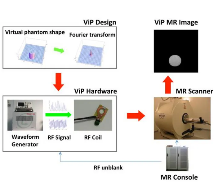
Virtual Phantom. A schematic representation of the ViP MRI method and experimental set-up is
illustrated in Figure 1. First, a phantom of a given shape was designed. The k-space representation was generated by Fourier transform and converted in a table of RF amplitudes and phases, which served as the input of the waveform signal generator (Redstone, Tecmag Inc., Houston, TX, USA).
The waveform signal generator, a compact unit of 48cm chassis operating in the 5-500 MHz frequency range, provided a high flexibility with respect to programming arbitrary pulse shapes, so to generate virtual phantoms of different shapes and signal intensity. The waveform signal generator was positioned outside the scanner room.
A home-built 15mm-diameter RF coil (the ‘ViP coil’) was connected to the waveform generator with a coaxial cable that was passed through the filter panel into the scanner room. The ViP coil was fixed within the scanner bore at a distance of 40 cm from the scanner RF coil and was employed to transmit the RF signal of the virtual phantom. At 4.7 T, (wavelength of the electromagnetic radiation = 1.5 m) the distance of 40 cm (< 1.5 m) ensured the inductive coupling between the ViP coil and the scanner RF coil, so that changes in the subject environment would equally affect the signal of the virtual and physical phantom. A low quality factor (1 to 5) ensured that ViP coil did not interfere with the scanner RF coil.
MRI experiments. MRI experiments were performed on a 4.7 T MR scanner (47/40 Biospec,
Bruker, Wissembourg, France). A 72mm-diameter volume coil (i.e., the scanner RF coil) was used as a transmitter/receiver. The carrier frequency of the waveform generator was adjusted to the main frequency of the Biospec (200 MHz). The k-space lines of the virtual phantom were played line-by-line in synchronization with the MRI data acquisition, using the unblanking RF signal from the MR console (Figure 1). In other words, during the MR experiment the ViP signal was injected into the scanner bore and recorded by the scanner receiver coil at the same time as the signal from the physical phantom. Fine-adjustments were necessary to ensure that the signal of the virtual phantom was well synchronized with the analog-to-digital converter of the MR scanner. For each experiment, the MRI data acquisition parameters (echo time, number of averages, dwell time, matrix size) were programmed into the waveform generator so that the ViP signal would be compatible with the MRI sequence. It should be also noted that, for the sequences employed in the current study, all the parameters necessary to generate the ViP signal were available to the normal user and simply accessible on the user interface of the MR scanner.
5 A number of different experiments were performed to assess the ability to generate virtual phantoms and control the ViP signal. In each experiment, one or more physical phantoms (tubes filled with agar + gadolinium at different concentrations) were also employed. Initial pilot experiments were performed in single-echo mode, to verify the capability of generating phantoms of different shapes. Further, a multi-echo experiment was performed with a virtual phantom of a given T2, in order to determine whether the ViP signal intensity at different echo times could be precisely controlled. A Carr-Purcell-Meiboom-Gill (CPMG) imaging sequence was employed with six echo times (TE = 20, 40, … 120 ms), matrix size of 256 x 256, field of view (FOV) of 5 x 5 cm2 and dwell time = 20 µs.
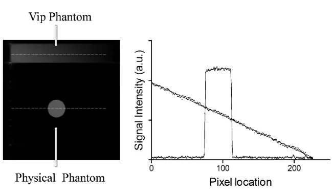
To determine the spatial linearity of the ViP signal within an MR image, a virtual phantom in the form of a ‘signal ramp’ was designed and a gradient-echo image of the virtual phantom and a tube filled with agar was acquired (repetition time TR = 100 ms, TE = 5 ms, matrix size of 256 x 256, FOV of 5 x 5 cm2 and dwell time = 20 µs).
To measure the ViP signal stability, experiments repeated over the course of a few hours were performed. Two time series of spin-echo images of a virtual phantom and a tube filled with agar were acquired. Imaging acquisition parameters were: TR = 1000 ms, TE = 16.7 ms, matrix size = 512 x 256, FOV = 8 x 8 cm2, slice thickness = 5 mm and dwell time = 20 µs. At each time point, the signal of the virtual and physical phantom was assessed in an ROI selected within the phantom. The mean value of the signal and its standard deviation over the time series was then evaluated and the coefficient of variation (defined as the standard deviation divided by the mean, expressed as a percentage) was used to characterize the time stability.
Results
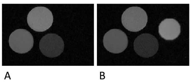
MR images of virtual phantoms were obtained for different types of acquisitions, including single-slice, multi-single-slice, multi-echo 2D and 3D acquisitions. An example of an MR image of a physical phantom (three tubes filled with agar + gadolinium at different concentrations) and of the same physical phantom with a virtual phantom is shown in Figure 2. A multi-echo acquisition of the physical and virtual phantom is illustrated in Figure 3. The values of signal intensity from ROIs selected in the three agar phantoms and in the virtual phantom are plotted as a function of the echo time. The virtual phantom was designed with a transverse relaxation time of 60 ms. The measured transverse relaxation time was equal to 59.9 ± 1.4 ms.
An MR image of a virtual phantom characterized by a signal ramp and of a tube filled with agar is shown in Figure 4, left panel. The signal intensity of the virtual and physical phantom, evaluated along the profile indicated by the dashed line, is plotted in Figure 4, right panel. Excellent linearity was observed in the ViP signal, along the frequency encoding direction, with coefficient of determination r2 = 0.9971 as determined by linear regression. To determine the time stability of the ViP signal, repeated measurements were performed over a few hours. The time course of the mean value of signal taken in an ROI of the virtual and physical phantom is illustrated in Figure 5. Two series of measurements, one short (n = 6) and the other longer (n = 15), were performed with a time interval of 16 hours. The coefficient of variation of the signal intensity calculated for the long series was equal to 0.29% and 0.28% in the virtual and physical phantom, respectively. When calculated over the two series (i.e., using all the measurements), the coefficient of variation was equal to 0.93% and 0.49% in the virtual and physical phantom, respectively.
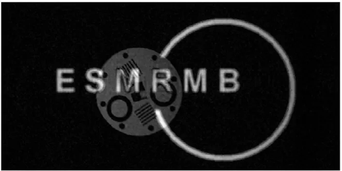
Figure 6 illustrates an example of the flexibility of the ViP MRI method for generating phantoms of complex shapes. An MR image of the quality-control phantom and a very unique virtual phantom (the logo of the European Society for Magnetic Resonance in Medicine and Biology -ESMRMB-) is shown in Figure 6 (TR = 500 ms, TE = 16.7 ms, matrix size of 512 x 256 and dwell time = 20 µs). The ESMRMB logo was purposely designed to overlap with the physical phantom. In regions where the virtual and physical phantoms overlap, as in one part of the letter ‘S’ or of the ring-shaped curve, it could be noted that the signal intensity of the virtual phantom is added to that of the physical phantom.
7
Discussion
Quantitative MRI is becoming increasingly important in both clinical and research settings. Traditionally, the diagnosis based on clinical MRI examinations has relied on assessing differences in signal intensity between healthy and diseased tissues rather than on absolute measurements of tissue parameters/characteristics. In the last decade, on the other hand, there has been a rapid shift towards more quantitative approaches. As a matter of fact, nowadays in many important clinical scenarios (cancer, neurological disorders, etc.) quantification of the relaxation times and apparent diffusion coefficient of water molecules is employed for improving diagnosis and therapy monitoring by MRI. Similar situation occurs in MRS, where precise quantification of metabolites in brain, prostate and liver is of primary importance. For quantification purposes, a reference signal is required. In this context, virtual phantoms represent an attractive alternative to physical phantoms for providing a reference signal. The results of this study show the flexibility and performances of virtual phantoms as implemented in the ViP MRI approach. Virtual phantoms of complex patterns can be reproduced well in an MR image without the presence of artifacts, provided that the details of MRI data acquisition (timings, k-space trajectory, etc.) are known. A given signal value can be well represented, as shown by the multi-echo decay data. Furthermore, the preliminary validations carried out in the current study show excellent stability over the short-term and linearity of the ViP signal.
Different hardware implementations and variants of the original ERETIC method have been proposed recently [7, 9]. These include the use of the second RF channel of the MR scanner, or the use of a single RF channel for non-simultaneous measurements, for instance. One of the advantages of the ViP MRI approach is that it can be performed on different MR scanners, since the ViP hardware is an independent, self-contained unit. No hardware or software components of the MR scanner are used for generating the signal of the virtual phantom with the exception of a trigger signal, which nowadays is readily available and accessible on basically all pre-clinical and clinical scanners. Thus, overall there is no need to access the MR scanner programming environment, which in some cases might not be available to the user.
With respect to the evaluation of MR scanner performances, the ViP MRI can be used for quality control measurements of the MR scanner receiver chain. It should be stressed here that with ViP MRI, as with all the other methods based on the ERETIC concept, it is not possible to assess MR pulse sequence flaws or mis-adjustments (imperfect refocusing 180º pulses, for instance) or MR scanner specifications (such as gradient non-linearity). This is due to the fact that the ViP signal is transparent to all RF pulses and magnetic gradient pulses of the MR sequence. In the current
study, the ViP MRI method was tested on phantoms and the ViP RF coil was positioned at a distance of 40 cm from the scanner RF coil. For in vivo applications, an investigation of the optimal ViP RF coil positioning would be necessary in order to minimize radiation effects.
The most direct application of ViP MRI would be to provide a reference signal for ‘proton density’ in 1
H MRI. More interestingly, this application can be extended to MRI of nuclei other than 1H, such as 19F and 23Na [9]. As matter of fact, to determine the concentration of the total sodium in tissues, physical phantoms are routinely used [10]; in this case also, virtual phantoms could be used to provide a reference signal, so to replace the physical phantoms. Furthermore it should be also noted that, in analogy to the approach of Hanson et al. [11] where physiological recording were encoded in real time on the MRI images, other applications of ViP MRI could include the encoding of additional data such as text and graphs, for instance. Finally, as analytical phantoms are increasingly being used to test and validate MR algorithms, such as reconstruction algorithms for instance [12], the ViP MRI could be also used for generating images of complex analytical phantoms with realistic noise characteristics.
9
Conclusion
In conclusion, MR images of virtual phantoms that could provide a reference signal for quantification were obtained using a stand-alone, independent unit. Thus, ViP MRI can be performed on MR scanners from different vendors.
Acknowledgements
Hervé Saint-Jalmes and Giulio Gambarota gratefully acknowledge the generous support of Rennes Métropole and Région Bretagne.
References
1. Barantin L, Le Pape A, Akoka S (1997) A new method for absolute quantitation of MRS metabolites. Magn Reson Med 38(2):179-182.
2. Michel N, Akoka S (2004) The application of the ERETIC method to 2D-NMR. J Magn Reson 168(1):118-123.
3. Martínez-Bisbal MC, Monleon D, Assemat O, Piotto M, Piquer J, Llácer JL, Celda B (2009) Determination of metabolite concentrations in human brain tumour biopsy samples using HR-MAS and ERETIC measurements. NMR Biomed 22(2):199-206.
4. Albers MJ, Butler TN, Rahwa I, Bao N, Keshari KR, Swanson MG, Kurhanewicz J (2009) Evaluation of the ERETIC method as an improved quantitative reference for 1H HR-MAS spectroscopy of prostate tissue. Magn Reson Med 61(3):525-532.
5. Ziarelli F, Viel S, Sanchez S, Cross D, Caldarelli S (2007) Precision and sensitivity optimization of quantitative measurements in solid state NMR. J Magn Reson 188(2):260-266.
6. Heinzer-Schweizer S, De Zanche N, Pavan M, Mens G, Sturzenegger U, Henning A, Boesiger P (2010) In-vivo assessment of tissue metabolite levels using 1H MRS and the Electric REference To access In vivo Concentrations (ERETIC) method. NMR Biomed 23(4):406-413.
7. Marro KI, Lee D, Shankland EG, Mathis CM, Hayes CE (2011) Synthetic signal injection using a single radiofrequency channel. J Magn Reson Imaging 34(6):1414-1421.
8. Franconi F, Chapon C, Lemaire L, Lehmann V, Barantin L, Akoka S (2002) Quantitative MR renography using a calibrated internal signal (ERETIC). Magn Reson Imaging 20(8):587-592.
9. Lee D, Marro K, Shankland E, Mathis M (2010) Quantitative 19F imaging using inductively coupled reference signal injection. Magn Reson Med 63(3):570-573.
10. Christensen JD, Barrère BJ, Boada FE, Vevea JM, Thulborn KR (1996) Quantitative tissue sodium concentration mapping of normal rat brain. Magn Reson Med 36(1):83-89.
11. Hanson LG, Lund TE, Hanson CG (2007) Encoding of electrophysiology and other signals in MR images. J Magn Reson Imaging 25(5):1059-1066.
12. Guerquin-Kern M, Lejeune L, Pruessmann KP, Unser M (2012) Realistic analytical phantoms for parallel magnetic resonance imaging. IEEE Trans Med Imaging 31(3):626-636.
11
Figures
Figure 1. Schematics of the experimental apparatus for Virtual Phantom (ViP) MRI. The first step
consists in designing the phantom shape and generating the k-space representation. The waveform generator of the ViP hardware converts the simulated k-space lines into RF signal that is transmitted by a dedicated RF coil, positioned in the scanner bore in proximity of the scanner RF coil. The ViP RF signal is synchronized with the MR scanner data acquisition by the RF unblank signal from the MR console. An oscilloscope was also part of the ViP hardware, in order to verify that the timings were properly implemented.
Figure 2. Proof of concept of Virtual Phantom (ViP) MRI. The MR image of three tubes filled
with agar + gadolinium at different concentrations (physical phantom) is shown in panel A. The same acquisition was repeated with the ViP signal (panel B). The ViP tube is well represented and can provide a reference value for the MR signal intensity. Imaging acquisition parameters were: repetition time = 500 ms, echo time = 20 ms, matrix size of 256x256 and dwell time = 20 µs.
13
Figure 3. Multi-echo MR imaging of virtual and physical phantoms. The physical phantom
consists of three tubes filled with agar + gadolinium at different concentrations. Signal intensities from ROIs selected in the virtual and physical phantoms are plotted as a function of TE. The monoexponential fit to the data is represented by the continuous line. The virtual phantom was designed with a transverse relaxation time equal to 60 ms. The transverse relaxation time obtained from data fitting was 59.9 ± 1.4 ms.
Figure 4. The MR image (left panel) and the plot of the signal intensity (right panel) of a virtual
and physical phantom. The signal intensity illustrated on the plot is taken along the profiles represented by the dashed lines on the image. The virtual phantom was designed in the shape of a ramp, with linear signal intensity. For the virtual phantom, the continuous line on the plot represents the linear regression of the signal intensity values. For the real phantom, the continuous line is the connecting line of the signal intensity values.
15
Figure 5. A spin-echo MR image (left panel) and the plot of the signal intensity at different times
(right panel) of a virtual (symbols ‘●’) and physical phantom (symbols ‘○’). MR images were acquired every two minutes and an interval of 16 hours was taken between the two series of measurements. The signal stability of the virtual phantom is comparable to that of the physical phantom, with a coefficient of variation below 1%.
Figure 6. The MR image of a quality-control phantom and a virtual phantom (the logo of the
European Society for Magnetic Resonance in Medicine and Biology, ESMRMB). The ESMRMB logo was purposely designed to overlap with the physical phantom. The elaborate shape of the ESMRMB logo (the letters and the incomplete ring-shaped curve) is well reproduced.