Academic and Research Staff
Prof. D. Kleppner Dr. M. T. Myint Dr. C. A. Kocher Dr. D. E. Pritchard
Graduate Students
G. M. Carter E. M. Mattison F. G. Walther
F. Y. Chu P. F. Winkler
A. WORK COMPLETED
1. SPIN-EXCHANGE COLLISIONS BETWEEN ALKALI ATOMS AND TARGETS OF ARBITRARY SPIN IN A UNIFORM
MAGNETIC FIELD
This research has been completed and a thesis with the same title was submitted by Gary M. Carter to the Department of Physics, M. I. T. , in April 1969, in partial fulfill-ment of the requirefulfill-ments for the degree of Master of Arts.
D. E. Pritchard
B. RELATIONSHIP OF THE ACTION AND THE SEMI-CLASSICAL SCATTERING AMPLITUDE
1. Introduction
We shall show how to interpret Ford and Wheeler's semi-classical expression for the scattering amplitude as an integral of the action over all impact parameters. This formulation clarifies the relationship between the action and the phase of the semi-classical expression for the scattering amplitude and lends physical insight into the angu-lar dependence of interference processes in scattering.
In quantum-mechanical treatments of scattering the impact parameter cannot be known because of the uncertainty principle (the transverse momentum before the colli-sion is fixed by the incident angle and momentum). If the de Broglie wavelength
,- -
Ii
(1)P /12mE
is much smaller than the scale of variation of the potential, however, the impact param-eter, b, becomes physically significant. One can imagine that each portion of the inci-dent wave can be followed through the collision; its deflection being determined only
This work is supported by the Joint Services Electronics Programs (U. S. Army, U.S. Navy, and U.S. Air Force) under Contract DA 28-043-AMC-02536(E).
by b (and the reduced potential). In this report we show how to express the scattering amplitude as an integral of the action over the impact parameter, and we show how this treatment simplifies the understanding of interference phenomena observed in thermal-energy atom-atom scattering experiments. We also present a simple derivation of the impact approximation for the phase difference in resonant exchange collisions (for example, spin exchange or resonant charge exchange).
Ford and Wheeler1 have shown that a considerable mathematical simplification in the usual partial-wave treatment of scattering results when the de Broglie wavelength is smaller than the scale of variation of the potential. By making a related set of approx-imations, collectively called the semi-classical approximation, they show that the scat-tering amplitude may be written
f(O) = -X(2T sinO) +
e+
- e3
d (2)where
+=
21(2)
+(
+
4 (3)and the phase shift, ii(f), is to be considered a continuous function of f (and may be found consistently from the JWKB approximation).
We introduce the impact parameter by means of the usual correspondence relation-ship
+
L /h
b/.
(4)
The angular momentum, L, can have either sign, but f (and also b) is restricted to positive values. We rewrite Eqs. 2 and 3, using the impact parameter
f(o) = -(2-7r sin 0) 1 b e - e 1db (5)
0
whereb 6 (6)
The function '9(b) equals 9i(f) when b equals
2X.
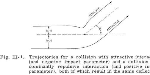
This follows naturally from the JWKB expression for 11(2); iq(b) is also closely related to the classical phase.2The expression in Eq. 5 is physically misleading because only regions with b > 0 contribute to the scattering amplitude, while it is clear (see Fig. III-1) that processes with either a net repulsive interaction and positive impact parameter or a net attractive
Fig. III-1.
Trajectories for a collision with attractive interaction
(and negative impact parameter) and a collision with
dominantly repulsive interaction (and positive impact
parameter), both of which result in the same deflection.
interaction and negative impact parameter can contribute to the scattering at positive
angles.
This fact is accounted for by the two terms in Eq. 5; the term 4
_
contributes
for repulsive scattering, the I)+ for attractive scattering. A more meaningful
expres-sion may be obtained by changing the variable of integration for the
+ term from b
to -b, since then the attractive scattering will occur with negative impact parameter,
-irrb
as it should. We accomplish this by making the substitution b'
=
e
,
so that the
inte-gral with 4 + in Eq. 5 becomes
db bl/2 exp
i 2(b) +
6 +
=-
db'(e-i b')l/2 exp i
(-b') -
+
=
db' by'/2
exp i
1(-b)
.
(7)
Note that r(-b)
=
T(b), so that the exponent in this expression is the same as the
expo-nent in the
-integral in Eq. 5.
We can now write the scattering amplitude as an
inte-gral containing 0_ over the whole range of b.f(O) = KX(2 sin )-1/2 db b/2 exp
)
2(b)-b
.
(8)This expression is simpler and more natural than Eq. 5, since all impact
param-eters now can contribute to the scattering amplitude.
An additional simplification
results because the exponent is closely related to the action. F. T. Smith has defined
the collision action A (hereafter called simply the action) to be the difference between
the total action with the potential V "on" and with it "off" (in which case the path
is straight):
A(, b)
=
p
dq -
dqo
(9)
where the total energy is fixed. He shows that each term may be broken into radial and
tangential components, the radial component being twice the JWKB phase shift, and the
tangential component being proportional to the angular momentum and to the scattering
angle.
A(O, b) =
2hi(b)
-bO.
(10)-K
The radial component is independent of the sign of b (that is, r(-b)
=
Y(b)), while the
angular term shows more action for collisions with b
<
0, since this corresoonds to the
"outside track."
Our expression for the scattering amplitude (Eq. 8) is simply expressed in terms
of the action
f(O)
e-i r/4(2 -Tr
sin)-/2
1/2 iA(O, b)/h
(11)
= db b e (11)
This expression is similar to the formulation of quantum mechanics that is due to
Feynman,3 which was extended by Motz,4 in which the amplitude for a particle to move
from one place to another is expressed as an integral over all possible trajectories of
exp(iS/h), where S is the action. (In our analogy the b1/2 weights the trajectories with
larger b more heavily because there are more of them.)
Our expression for the scattering amplitude may be integrated by the stationary phase
technique, since the action is a rapidly changing function of b except at a few impact
parameters, b
i, where
A(O, b) = 0, (12)
b
b.
1 which occurs where
2l'(bi)
0
(13)1-X
In the neighborhood of these stationary points the action may be expressed
2 A(O, b) ~ A(O, b.) 1 a A (b-b.)2 S 2 b 2 b b
b=b
i A(6,b.)
+ lil"(b.)(b-b.) . (14) 1 1 1The stationary phase integration must be performed at each impact parameter where the action is stationary, so the scattering amplitude becomes a sum over all impact parameters b. that satisfy Eq. 13.
1
f(0) =
b.(6)
fbiI(2b.x
sin
6-1"(bi))
-1/2 etA(o
bi)/Ih
(15)
(This expression fails if 0
=
0, or ir [glory scattering], or
"(b i)
=
0 [rainbow
scat-tering].) All quantities must be treated as complex numbers, so that a factor e willresult if either bi or -"(b
i )is negative.
(If b < 0 in Eq. ii,
b
must be interpreted
as e -i/Z Ib 1/2, because of the transformation used in Eq. 7.)Equation 15 shows that contributions to the scattering amplitude come from (the
neighborhood of) discrete values of the impact parameter.
The magnitude of each
con-tribution is determined by the angle, the impact parameter, and the second derivative
of the phase.
The phase of each contribution is determined solely by the action (apart
from a possible constant). This makes our analysis especially enlightening when applied
to scattering processes that are sensitive to the phase of the scattering amplitude
(or its components).
2. Simple Elastic Scattering
Let us now consider the application of these results to elastic scattering by a single
potential.
Since the proceeding results are most helpful in simplifying the discussion
of scattering when more than one impact parameter contributes to the scattering, we
consider a potential that, like most interatomic potentials, is attractive at long distances
and repulsive at short distances.
The phase function r
1(b) for this potential is shown
in Fig. III-2. We also show the classical deflection function
x(b) = 2 -K'(b),
(16)
which is the locus of points where the action is stationary (that is, where Eqs. 12 and 13 hold). The lower half of the deflection function is shown dashed to emphasize that only impact parameters for which x(b) = 0 contribute to f(6) in Eq. 15 (0 is the angle of obser-vation, and is always positive). Thus at angle 06 (in Fig. III-2), three impact param-eters contribute to the scattering amplitude, bl, b2, and b3; b1 and b2 are both negative
and correspond to predominantly attractive scattering, while b is positive and corre-sponds to predominantly repulsive scattering.
When two (or more) impact parameters contribute to the scattering amplitude in Eq. 15 the differential cross section will contain interference terms where phase dif-ference varies as [A(6, bl(0))-A(6,b 2(0))]/h. The angular spacing of the resulting
7 (b)
i/
bl b
2
Fig. III-2.
Phase function, r(b), and deflection function, x(b); each shown for both positive and negative values of impact parameter, b.maxima and minima in the cross section depends on the total rate of change of the action with 0. This is
d
aA
A
d A(O, b.(6)) = de- bi b i = -hbi/-K db. de(17)
from Eq. 10 (the second term
tering at some angle, then the
neighborhood is given by
is zero from Eq. 13). If b1 and b2 both contribute to
scat-angular spacing of successive maxima or minima in that
d
A6 -
d
(A(,
bl)-A(O, b
2))
=2Tr,
so that
(18) -- b--- TAO
= (19) bl(6) - b 2()
Thus the local spacing of maxima and minima is determined solely by distance between
b1 and b
2; the potential plays no role, once b
1and b
2have been determined.
Equation 19 also describes the spacing of maxima and minima in the two-slit
diffrac-tion of monochromatic light (Young's experiment), stressing once again the wave nature
of matter. The b
ichange with angle so that the spacing of successive maxima and minima
is not constant in the scattering cross section, as it is in Young's experiment.
Equation 10 may be used to determine the distance between the impact parameters
that contribute to the scattering amplitude.
As an example we consider Hundhausen and
Parly's
6data for Na-Hg scattering at Vrel = 1.475 X 105 cm/sec (X is 0. 1303 A at this
velocity).
They observe interference between b
1and b
2(supernumerary rainbows) with
a period of 0.09 rad, which implies that b
1-
b
2=
1. 5 A; and they observe interference
between bl and b
3(rapid oscillations) with a period of 0.0127 rad, which implies that
b1 - b
3= 10.2 A. These distances are quite compatible with the size of the potentials
which they determined by partial-wave analysis.
3.
Resonant Exchange
Let us now consider a typical exchange cross section
ex () = I f+(0)-f ()J 2
(20)
where f+ and f_ are two independent scattering amplitudes.
Such expressions arise in
spin exchange and in resonant charge exchange; in both processes the expected
oscil-latory structure has been observed.
As in single-channel scattering, the oscillatory
behavior is due to interference between the two scattering amplitudes whose phase
dif-ference varies as the difdif-ference between the two actions times 1/h.
The local change
of action with 0 depends only upon b (and not on the potential, see Eq. 17), so we find
the angular spacing of successive maxima and minima in the exchange cross section to
be
A0 =
X
(21)b (6) - b_(6)
in the neighborhood of 0.
Frequently, it is possible to infer the phase difference between the two scattering
amplitudes exactly, in which case we can measure the relative phase
We assume that the potentials have similar shapes, so the additional Tr/4 terms in Eq. 15 cancel out. Although the impact parameters in the plus and minus states are different, the action is stationary for small variations of b, so if b+ and b_ are approximately
equal (as they will be if the potentials for the two states are nearly equal), we can approximate
6(0)
[A+ (, b)- A_(O, b)]/
=
2~1(b)
- 2Z _(b), (23)where b = (b +b_)/2, and the second line follows from Eq. 10. Use of the first term
2
of the impact approximation for -i (b) yields the familiar result
6(0) j - V d V df
- i V df, (24)
b
where 6V is the difference potential V -V_, and v is the relative velocity of the collision. 7
The argument frequently used to derive Eq. 24, under the assumption that the impact parameter is the same for collisions in both states, is incorrect; the "par-ticle" in the state with weaker potential must travel closer to the target in order to sustain the deflection 0. In so doing, it travels in a region of deeper potential and picks up some extra phase (nr). The phase of the scattering amplitude is gov-erned, however, by the action, which is also affected by the decrease in path length caused by passing closer to the target. These two effects cancel exactly, since the action is stationary, so Eq. 26 is correct. A similar argument also applies for domi-nantly repulsive potentials.
D. E. Pritchard
References
1. K. Ford and J. Wheeler, Ann. Phys. 7, 259, (1959).
2. F. T. Smith, J. Chem. Phys. 42, 2419 (1965). 3. R. P. Feynman, Rev. Milod. Phys. 20, 367 (1948).
4. L. Motz, Phys. Rev. 126, 378 (1962).
5. H. Pauly and J. P. Teonnies presented a viewpoint similar to ours in Advances in Atomic and Molecular Physics 2, 201 (1965).
6. E. Hundhausen and H. Pauly, Z. Physik 187, 305 (1965) have obtained a similar for-mula by a different argument.
7. See, for example, D. R. Bates, H. S. W. Massey, and A. L. Stewart, Proc. Roy. Soc. (London) A216, 437 (1963).
B. NEW DETERMINATION OF HYDROGEN-DEUTERIUM g-FACTOR RATIO
1. Introduction
The one-electron atom has a rich history as a proving ground for comparing theory and experiment to extraordinarily high precisions. In this report we propose a new com-parison of the electronic g-factor in hydrogen and deuterium as a check on high-order terms to the electronic shielding corrections.
The nonrelativistic theory of hydrogen predicts that the g-factor in the ground state (2 ZS1/2) is gj(H) = gs, where gs is the g factor of the free electron. As shown by Breit, 1 in an early paper, relativistic effects alter this to g (H) = gs (l- a2/3) This is
2 3 2
correct to order a . There are further corrections of order a and a m/M, which are due to the effect of binding on the anomalous moment, and to reduced mass effects. Hegstrom2 has derived the following result.
2
2gj(H) = gl - La Z + 1 3 Z2 VI) +
j
s 3 m+M) 12r m+M ewhere 6 represents the correction to the anomalous moment caused by binding of
e 3 33
the electron, and is of order a .
This result can be checked by comparing electronic transitions in hydrogen and deuterium in a hydrogen maser. Details of our apparatus have been given in previous reports, and we describe here only the more important modifications that are needed.
The energy levels for hydrogen and deuterium are shown in Fig. 111-3. At the field of our magnet, 3500 G, the transition frequencies are tabulated as follows:
Hydrogen Deuterium
Transition Frequency (GHz) Transition Frequency (GHz)
1-2 0.6444 3-4 9.6465 3-4 0.7760 3-5 9.7603 2-3 9.2029 2-5 9.8671 2-4 9.9979 3-6 9.8717 1-4 10.6233 2-6 9.9785 1-6 10.0829
Several of the transitions lie relatively close to each other. In particular, the 2-6 transition in deuterium lies only 0.39 MHz below the hydrogen 2-4 transition. This pre-sents the possibility of measuring the two transitions simultaneously, which has impor-tant practical advantages.
1
1
2
2
3
F = 3/2
F =
1
F = 1/2
F =0
4
3
5
4
6
DEUTERIUM
HYDROGEN
Fig. 111-3. Energy levels as a function of external
magnetic field.
g-factor comparisons traditionally consist in successive determination of transition
fre-quencies of two species. Since the frefre-quencies depend linearly on the applied magnetic
field, the experimental precision is usually limited by the field stability. Thus, if the
two species can be examined simultaneously, problems of field stability, and other
prob-lems having to do with sample interchange, are much reduced. This technique underlies
our current determination of the electron-proton magnetic moment ratio.
4At the present time, our maser produces an electronics transition in hydrogen with
a lifetime of 5 msec, at a frequency of 9 GHz.
This corresponds to a linewidth of
70 Hz, or a resonance
Q
of v/Av
=
1.3X 10⁸. The signal-to-noise ratio is high, so that
the center of the line can be determined to a small fraction of its width.
Unfortunately,
short-term fluctuations in the field broaden the line significantly.
The fluctuations
AH/H are typically a few parts in 10 , so that the observed linewidths are often 200 Hz
wide.
The hydrogen and deuterium transitions, however, have a very similar field
dependence, and their ratio is practically field-independent. In the proposed experiment,
the hydrogen and deuterium are put simultaneously into a radiating state, and the ratio
of the frequencies is determined in the course of a single radiation lifetime. The ratio is
averaged many times over, in contrast to the more familiar technique of averaging each
transition frequency many times over before taking the ratio.
An error analysis of the proposed experiment has been carried out. It indicates that
gj(H)/g (D) can be measured to adequate precision to observe terms of order a 3, a m/M,
and possibly a4
A fundamental technical problem in the proposed experiment is that it requires a coherent microwave structure with response at two well-separated frequencies. The procedure for achieving this will now be presented.
2. Doubly Resonant Cavity
We require a detection system that is capable of simultaneously measuring the fre-quencies of two microwave signals in X-band which are separated approximately
100 MHz. Because the signals are so weak, the microwave detection system must have a response Q of ~104; this rules out the possibility of detecting both signals in a single cavity. The required system, therefore, must respond at two frequencies, each at approx-imately 10 GHz, separated ~100 MHz, with each response having a bandwidth of 1 MHz.
C1 C
2
L
L
Fig. III-4. Equivalent circuit for doubly
V.
2o
resonant cavity.
t1
R1 M R2
The system that we have developed comprises two microwave cavities with adjust-able, weak coupling between them. The response characteristics can be approximated by using an electrical RCL circuit analog (see Fig. III-4). Here circuits 1 and 2 are
simple RCL circuits, M is a mutual inductance between them, which represents the coupling, and circuit 1 contains a voltage-driving element, which represents the sig-nal source. In terms of the circulating charge in each circuit, the differential equa-tions of the system may be written
q Lll + Rl1 + + + M 2 V (la)
1
L2 2 + R2i2 + + M 1 = 0. (lb)2
In terms of microwave cavity parameters, these equations may be rewritten
lq1
2
V
91 1 2 (2a)
W2q2 2 (2b)
where 0.L. Z 1 M 1 W. - , K
Qi-
(i=1,2).
1
L.C.' K L. i R 11 1 1 itSince the system is driven, we assume V = V e and look for solutions ql
iwt iwt
al e ; q2 = aZ e , where al and a2 are complex constants representing the responses
of the two cavities. Equations 2 become
al 1i V0 a 2 Kl - W
l
Lo
F (w) V 1 o (3a) a 2(a
K1 L KK 1 al 2 -1+F2
= a
2 (3b) 2Solving Eqs. 3 for al, we find
V
a 1 -
(
2IK))
2
where K K 1K2. The interesting parameter is R, the relative response of circuit
1,
normalized to its response when K = 0 and w = w .
2
F
al( 1 , 0) 1(F ) - ZF
We now wish to find the frequencies for which R1 is a maximum to first order. These
correspond to the poles of the denominator of Eq. 4, which are given by
If we write w
=i 1+ A, and note that
K2<< 1 and (A/w
1) << 1, the solutions of Eq. 5
to order (A/w ) are
2 = - I ++ + . (6)
If we assume A
=
0, that is, wl =
W
,Eq. 5 has the solutions
S= w (I K). (7)
This result indicates that two frequency responses will occur, centered at ol and split
by
w I
K.The effective
Q
of the response lines can be estimated from Im {Fl (w)F
(w)},
2and
is found to be
Q1
Q2
eff
Q1
2
independent of K in this approximation.
Then assuming Q
1= Q
2,
we have
1