CONCEPTUAL DESIGN OF AN ANNULAR-FUELED SUPERHEAT BOILING WATER REACTOR
by YU-CHIH KO
B.S., Engineering and System Science (2002), National Tsing Hua University, Taiwan M.S., Engineering and System Science (2004), National Tsing Hua University, Taiwan M.S., Nuclear Science and Engineering (2008), Massachusetts Institute of Technology
Submitted to the Department of Nuclear Science and Engineering in partial fulfillment of the requirements for the degree of
DOCTOR OF PHILOSOPHY IN NUCLEAR SCIENCE AND ENGINEERING at the
MASSACHUSETTS INSTITUTE OF TECHNOLOGY September 2010 fe
0 2010 Massach
Signature of Author:
Certified by:_
Certified by:
usetts Institute of Technology. All rights reserved.
Departmenteof Nuclear Science and Engineering September 29, 2010
Mujid S. Kazim',Fh)sis Supervisor TEPCO Professor of ka46r Engineering
Jacopo Buo iorno, Thesis Reader Associate Pro s or of Nuclear S tfience and Engineering
Accepted by:
Mujid S. Kazimi
ACWNES
CONCEPTUAL DESIGN OF AN ANNULAR-FUELED SUPERHEAT BOILING WATER REACTOR
by YU-CHIH KO
Submitted to the Department of Nuclear Science and Engineering on September 29,2010 in partial fulfillment of the
requirements for the degree of
DOCTOR OF PHILOSOPHY IN NUCLEAR SCIENCE AND ENGINEERING ABSTRACT
The conceptual design of an annular-fueled superheat boiling water reactor (ASBWR) is outlined. The proposed design, ASBWR, combines the boiler and superheater regions into one fuel assembly. This ensures good neutron moderation throughout the reactor core. A single fuel design is used in the core. Each annular fuel element, or fuel tube, is cooled externally by boiling water and internally by steam. Fuel pellets are made of low enrichment U02, somewhat higher than the traditional BWR fuel enrichment. T91 and Inconel 718 are selected as candidates for the cladding material in view of their excellent physical properties and corrosion resistance. The fuel-cladding gap is filled with pressurized helium gas, like the existing lighter water reactor fuels. The ASBWR fuel assembly contains sixty annular fuel elements and one square water rod (occupying a space of four fuel elements) in an 8 by 8 square array. Annular separators and steam dryers are utilized and located above the core in the reactor vessel. Reactor internal pumps are used to adjust the core flow rate. Cruciform control rods are used to control the reactivity of the core, but more of them may be needed than a traditional BWR in view of the harder spectrum.
The major design constraints have been identified and evaluated in this work. The ASBWR is found promising to achieve a power density of 50 kW/L and meet all the main safety requirements. This includes a limit on the minimum critical heat flux ratio, maximum fuel and cladding operating temperatures, and appropriate stability margin against density wave oscillations.
At the expected superheated steam of 520 *C, the plant efficiency is above 40%, which is substantially greater than the efficiency of 33 to 35% that today's generation of LWRs can achieve. In addition to generating electricity, the ASBWR may also be useful for liquid fuel production or other applications that require high temperature superheated steam.
internal coolant channels throughout the fuel cycle, and the response to the traditional transients prescribed as design basis events.
Thesis Supervisor: Mujid S. Kazimi
Title: TEPCO Professor of Nuclear Engineering Thesis Reader: Jacopo Buongiorno
ACKNOWLEDGEMENTS
I would like to express my deepest appreciation to Professor Mujid S. Kazimi for his supervision and encouragement during the past four years of my life. Working with Prof. Kazimi has been not only an honor, but also a very enriching experience for me, both personally and professionally. I particularly like his sense of humor, which has made all the regular group meetings so enjoyable. I am also grateful to my thesis reader, Prof. Buongiorno. This work has been modified based on his valuable comments and recommendations.
I want to thank the following people for their help on specific issues of my work: Dr. Karahan for the fuel performance and neutronic calculations, Dr. Pilat for the literature review and LWR operating experience, Dr. Hejzlar for his guidance in the initial design phase of this work and Prof. Schulenberg for providing me the rare documentation of the German nuclear superheater.
Special thanks go to Prof. Min Lee, Dr. Lin-wen Hu and Dr. J. Bernard. Without their support, I would not have entered MIT, finished my master thesis with the LEU project and passed the doctoral qualifying exam.
A big "Thank You" to all of my Taiwanese friends at MIT and my friends at the NSE department: Hung-An, Shiu-Pei, Hsiang-Chieh, Chien-Jen, Sidney and Scott, Sam and Joyce, Cheng-wei, Wu-hsi, Chih-Chao, Podo, Hsin-Fu, Chih-yu, Jacqueline (Pipi), Duck, Peggy, Tsung-Han, Haru, Mike and Marina, Bo and Daphne, Vivek, David and Michelle, Ji-yong, Rui Hu, and Liang. I may have forgotten how to solve a two-group, two-region diffusion equation, but I will always remember our friendship and those wonderful memories that you have brought to me.
Furthermore, I would like to thank my family for their endless love and support. My dad and mom have been waiting for so long to see I finally finish my education. The tickets to the commencement will be one of the best gifts that I have ever presented to them. My sister should be happy enough to change her Facebook title to "Doctor's sister."
Lastly, I want to thank my dear wife, Yen-Chia Lin, for her selflessness and sacrifices in the course of our MIT journey. With a doctorate, I expect myself to be able to provide her a pleasant shopping experience wherever we will be living in the future.
TABLE OF CONTENTS ABSTRACT... .. 3 ACKNOWLEDGEMENTS... 5 TABLE OF CONTENTS... .... 7 LIST OF FIGURES ...- 11 LIST OF TABLES ... 15
ACRONYMS AND NOMENCLATURE... 17
Chapter 1 Introduction... 21
1.1 M otivation... 21
1.2 Background... 23
1.2.1 The Early Program in the United States... 23
1.2.2 Research Activities in Other Countries... 24
1.3 Objectives ... 26
1.4 Thesis Organization ... 26
Chapter 2 Literature Review of Superheat and Nuclear Reactors... 29
2.1 Categorization of the Superheat Nuclear Power Plants... 29
2.2 Comparison between Conventional and Nuclear Superheaters... 30
2.3 General Approaches on the Design of an Integral Nuclear Superheater ... 33
2.3.1 Key questions for the design... 33
2.3.2 Introduction of Direct and Indirect Heating Approaches... 35
2.3.3 Indirect Superheating Approach ... 38
2.3.4 Direct Superheating Approach... 40
2.3.5 Summary of the Design Approaches... 47
2.4 Summary of the Historical Superheat Nuclear Reactors ... 51
2.5 Summary of the Conceptual Designs of Nuclear Superheaters... 55
Chapter 3 The Annular-fueled Superheat Boiling Water Reactor ... 65
3.1 Design Considerations ... 65
3.2 General Description of the Proposed Design... 67
3.3 Detailed Description of the Proposed Design... 70
3.3.1 Reactor Vessel and Major Components ... 70
3.3.2 Flow Configuration... 71
3.3.3 Fuel Assembly... 74
3.3.4 Materials for the In-core and Out-of-core Structures... 91
3.3.5 Key Advantages of the Proposed Design... 95
3.3.6 Main Challenges of the Proposed Design... 98
3.4 Comparison between the HDR and the Proposed Design ... 100
3.4.1 Comparison of Fuel Element ... 101
3.4.2 Comparison of Fuel Assembly... 101
3.4.3 Overall Comparison between the HDR and ASBWR... 103
Chapter 4 Neutronic Analysis ... 111
4.1 Introduction...--- 11 4.2 Computational Tools...111
4.2.1 CASMO-4...111
4.2.2 MCNP-4C...111
4.3 Benchmarking: Comparison between MCNP and CASMO...112
4.4 Two-Dimensional Neutronics ... 114
4.4.1 Water Rod Design of the ASBWR Assembly ... 114
4.4.2 Burnup Calculation for the Poison-free Assembly ... 116
4.4.3 Distribution of Enrichment and Poison Rods in the ASBWR Assembly ... 118
4.4.4 Assembly Power Peaking Factors... 129
4.4.5 Void and Fuel Temperature Reactivity Coefficients ... 130
4.4.6 Considerations for the Control Rod Design... 131
4.5 Estimation of Fuel Cycle Length... 133
4.6 Impact of Enrichment on the Cost of Electricity ... 134
Chapter 5 Steady State Thermal-hydraulic Analysis ... 137
5.1 Computational Tools... 137
5.1.1 The MIT ASBWR Single Channel Analysis Code ... 137
5.1.2 VIPRE-O1... 137
5.2 Thermal-hydraulic Constraints for the ASBWR... 138
5.3 Single Channel Analysis ... 140
5.3.1 Assumptions... 140
5.3.2 Heat Loss in the Unheated Region... 141
5.3.3 Axial Temperature Profiles ... 142
5.3.4 Radial Temperature Profiles... 151
5.3.5 Impact of Power Density on Steam, Clad and Fuel Temperatures ... 156
5.3.6 Steam Velocity and Pressure Drop... 158
5.3.7 Water Power Split Fraction... 161
5.4 Assembly Subchannel Analysis... 162
5.4.1 Assumptions... 162
5.4.2 Heat Generation and Flow Rates ... 164
5.4.3 MCHFR Calculation... 166
5.4.4 Core Pressure Drop... 169
5.5 Startup Analysis for the ASBWR... 171
5.6 Proposed Startup and Shutdown Procedures for the ASBWR... 174
Chapter 6 Preliminary Thermal Expansion and Stress Analyses... 189
6.1 Assumptions and Cladding Properties... 189
6.2 Stresses Caused by Pressure ... 190
6.3 Calculation of Thermal Stresses ... 193
6.4 Calculation of Strains and Thermal Expansion... 195
7.1 Introduction ...-- 199
7.2 Computational Tool... 199
7.3 Modeling of the Annular Fuel for the Stability Analysis Code... 200
7.4 Single Channel Thermal-hydraulic Stability Analysis... 200
7.4.1 Assumptions... 200
7.4.2 Results... 202
7.5 In-Phase Stability Analysis ... 202
7.5.1 Assumptions... 202
7.5.2 Results... 205
7.6 Sensitivity Studies... 205
Chapter 8 Summary and Recommendations for Future Work... 207
8.1 Summary... 207
8.2 Conclusions... 215
8.3 Future Work ... 216
References ... ... ... 219
Appendix A Review of Historical Superheat Nuclear Reactors ... 227
A.1 Nuclear Power Plants with Fossil Fuel-fired Superheaters... 227
A. 1.1 The Elk River Reactor... 227
A. 1.2 Indian Point Nuclear Power Plant Unit 1... 232
A.1.3 The Carolinas-Virginia Tube Reactor (CVTR)... 235
A.2 Nuclear Power Plants with Non-integral Nuclear Superheaters... 240
A.2.1 The Vallecitos Experimental Superheat Reactor (VESR)... 240
A.3 Nuclear Power Plants with Integral Nuclear Superheaters... 244
A.3.1 The Atomic Power Station 1 (APS-1)... 244
A.3.2 The BORAX-V Reactor... 245
A.3.3 The Pathfinder Reactor ... 251
A.3.4 The Boiling Nuclear Superheater (BONUS) ... 260
A.3.5 The Beloyarsk Nuclear Power Station... 270
A.3.6 The Marviken Boiling Heavy-water Superheat Reactor (R4) ... 273
A.3.7 The German Superheat Nuclear Reactor (HDR)... 274
Appendix B The MIT ASBWR Single Channel Analysis Code... 283
B.1 Objectives of the MIT ASBWR Single Channel Analysis Code ... 283
B.2 Code Structure and Assumptions... 283
B.3 Models for the Temperature Calculation ... 291
B.3.1 Coolant Conditions... 291
B.3.2 Cladding Surface Temperature... 292
B.3.3 Cladding Temperature Drop... 293
B.3.4 Fuel-Cladding Gap Temperature Drop... 293
B.3.5 Fuel Pellet Temperature Distribution... 294
B .4.3 R esults... 297
B.5 Source Code... 300
Appendix C Subroutine for Generating VIPRE Input Files ... 325
Appendix D Derivation of the Lumped Annular Fuel Dynamics Model... 337
D.1 Derivation of the Lumped Fuel Dynamic Equations ... 338
D.2 Coupling of Fuel Dynamics to Coolant Thermal-hydraulics Model... 345
Appendix E Input Files... 347
E.1 VIPRE-01 Input for the ASBWR Assembly Analysis ... 347
E.2 MCNP Input for the Benchmark Study... 353
E.3 CASMO Input for the Benchmark Study... 356
E.4 CASMO Input for the ASBWR Assembly Analysis... 357
E.5 Single Channel Stability Analysis Input ... 358
LIST OF FIGURES
Figure 1-1 A non-ideal Rankine cycle with superheat... 22
Figure 2-1 Figure 2-2 Figure 2-3 Figure 2-4 Figure 2-5 Figure 2-6 Figure 2-7 Figure 2-8 Figure 2-9 Figure 2-10 Figure 2-11 Figure 3-1 Figure 3-2 Figure 3-3 Figure 3-4 Figure 3-5 Figure 3-6 Figure 3-7 Figure 3-8 Figure 3-9 Figure 3-10 Figure 3-11 Figure 3-12 Figure 3-12 Figure 3-13 Figure 3-14 Figure 3-15 Figure 3-16 Figure 3-17 Figure 3-18 Figure 3-19 Figure 3-20 Figure 3-21 Figure 3-22 Figure 3-23 Figure 3-24 Figure 4-1 Figure 4-2 Categorization of the superheat nuclear power plants ... 29
Key questions for the design of an integral nuclear superheater ... 36
Indirect and direct superheating approaches... 37
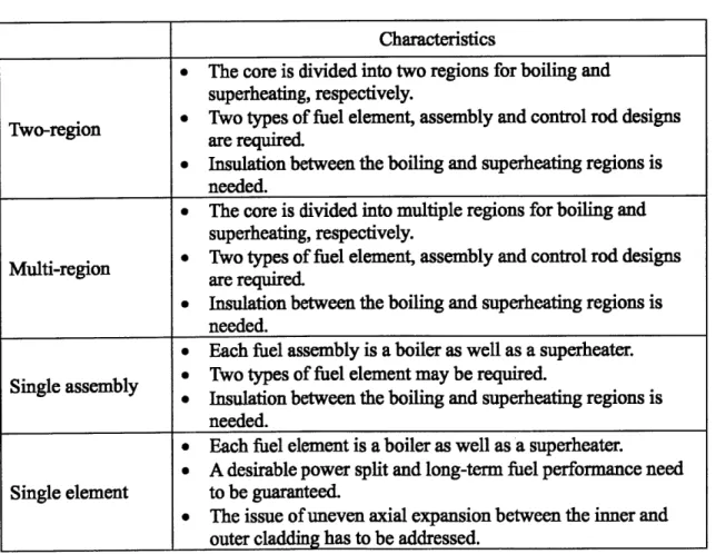
The two-region concept... 41
The multi-region concept... 44
The single assembly concept... 45
The single element concept... 46
Comparison of the four direct boiling and superheating design concepts ... 49
The ANL 1956 conceptual design... 56
The 2007 conceptual design of Ferrara and Hochreiter... 57
Flow path in the three pass core design concept ... 59
Simplified flow configuration of the ASBWR... 69
Steam temperature vs. plant efficiency for a superheat BWR ... 70
Reactor vessel and major components of the ASBWR... 72
Flow configuration of the ASBWR... 73
The ASBWR fuel assembly ... 75
Top, front and side views of the upper tie plate ... 76
Locations of the tie rods... 76
Cross-sectional view of the ASBWR fuel assembly (A-A)... 77
Cross-sectional view of the ASBWR fuel assembly (B-B)... 78
Cross-sectional view of the ASBWR fuel assembly (C-C)... 79
Cross-sectional view of the ASBWR fuel assembly (D-D) ... 80
The ASBWR annular fuel element... 81
The ASBWR annular fuel element... 81
The ASBWR annular tie rod ... 82
The ASBWR annular fuel element with annular spring seal ... 83
Spring system of the ASBWR fuel assembly... 84
The upper and lower steam boxes... 85
Three-dimensional view of the steam box ... 86
Flow paths in and around the steam box... 88
Horizontal cross-sectional view of the ASBWR fuel assembly... 89
Coolant flow paths in the ASBWR assembly ... 90
Comparison of steam flow path in the HDR and ASBWR fuel assembly 103 Comparison of a BWR fuel pin and the ASBWR annular fuel element.. 107
The reference BWR assembly module... 108
The ASBWR assembly module... 109
Initial design of the ASBWR assembly...116
Figure 4-5 Figure 4-6 Figure 4-7 Figure 4-8 Figure 4-9 Figure 4-10 Figure 4-11 Figure 4-12 Figure 4-13 Figure 4-14 Figure 4-15 Figure 4-16 Figure 4-17
Infinite multiplication factor versus burnup of the reference BWR ... 120
Enrichment and poison rod distribution of the ASBWR (Design A)... 120
Enrichment and poison rod distribution of the ASBWR (Design B)... 121
Enrichment and poison rod distribution of the ASBWR (Design C)... 121
Infinite multiplication factor versus burnup of the ASBWR (Design A)... 123
Infinite multiplication factor versus burnup of the ASBWR (Design B). 124 Infinite multiplication factor versus burnup of the ASBWR (Design C). 124 Enrichment and poison rod distribution of the ASBWR assembly using Inconel 718 cladding... 128
Infinite multiplication factor versus burnup of the ASBWR assembly using Inconel 718 cladding... 128
Fresh fuel PPFs of the ASBWR using T91 cladding ... 129
Fresh fuel PPFs of the ASBWR using Inconel 718 cladding... 129
Comparison of the conventional and ABWR-II control rod designs... 132
Breakdown of the nuclear electricity generation cost... 134
Figure 5-1 Axial power profiles of the ASBWR and reference BWR... 140
Figure 5-2 Axial coordinate of the ASBWR single channel model... 141
Figure 5-3 Axial temperature profiles of the water side (Hot channel, T91 cladding) 144 Figure 5-4 Axial temperature profiles of the steam side... 144
(Hot steam down-flow channel, T91 cladding)... 144
Figure 5-5 Axial temperature profiles of the steam side... 145
(Hot steam up-flow channel, T91 cladding)... 145
Figure 5-6 Comparison of the steam outlet temperature (T91 cladding)... 145
Figure 5-7 Comparison of the inner cladding temperature (T91 cladding)... 146
Figure 5-8 Comparison of the maximum fuel temperature (T91 cladding)... 146
Figure 5-9 Axial temperature profiles of the water side Figure 5-10 Figure 5-11 Figure 5-12 Figure 5-13 Figure 5-14 Figure 5-15 Figure 5-16 Figure 5-17 Figure 5-18 Figure 5-19 Figure 5-20 (Hot channel, Inconel 718 cladding)... 148
Axial temperature profiles of the steam side (Hot steam down-flow channel, Inconel 718 cladding)... 148
Axial temperature profiles of the steam side (Hot steam up-flow channel, Inconel 718 cladding)... 149
Comparison of the steam outlet temperature (Inconel 718 cladding)... 149
Comparison of the inner cladding temperature (Inconel 718 cladding).. 150
Comparison of the maximum fuel temperature (Inconel 718 cladding).. 150
Radial coordinate of the ASBWR single channel model... 152
Radial temperature profile of the hot steam down-flow channel (z = -10 cm , T91 cladding) ... 152
Radial temperature profile of the hot steam down-flow channel (z = 2.0 cm , T91 cladding)... 153
Radial temperature profile of the hot steam down-flow channe (z= 93.7 cm, T91 cladding)... 153
Radial temperature profile of the hot steam down-flow channel (z = 292 cm, T91 cladding)... 154
Radial temperature profile of the hot steam down-flow channel (z= -10 cm, Inconel 718 cladding)... 154
Figure 5-21 Figure 5-22 Figure 5-23 Figure 5-24 Figure 5-25 Figure 5-26 Figure 5-27 Figure 5-28 Figure 5-29 Figure 5-30 Figure 5-31 Figure 5-32 Figure 5-33 Figure 5-34 Figure 5-35 Figure 5-36 Figure 5-37 Figure 5-38 Figure 5-39 Figure 5-40 Figure 6-1 Figure 6-2 Figure 6-3 Figure 6-4 Figure 7-1 Figure 7-2 Figure A-1 Figure A-2 Figure A-3 Figure A-4 Figure A-5 Figure A-6 Figure A-7 Figure A-8 Figure A-9 Figure A- 10 Figure A-11 Figure A-12
Radial temperature profile of the hot steam down-flow channel
(z = 2.0 cm, Inconel 718 cladding)... 155
Radial temperature profile of the hot steam down-flow channel (z = 93.7 cm, Inconel 718 cladding)... 155
Radial temperature profile of the hot steam down-flow channel (z = 292 cm, Inconel 718 cladding)... 156
Sensitivity of power density for T91 cladding... 157
Sensitivity of power density for Inconel 718 cladding ... VIPRE model of the ASBW R assembly ... Power to flow operating map of a typical BWR... Calculation results of the startup analysis... Startup of the ASBW R (step 1)... Startup of the ASBW R (step 2)... Startup of the ASBW R (step 3)... Startup of the ASBW R (step 4)... Startup of the ASBW R (step 5)... Startup of the ASBW R (step 6)... Startup of the ASBW R (step 7)... Startup of the ASBW R (step 8)... Startup of the ASBW R (step 9)... Startup of the ASBW R (step 10)... Startup of the ASBW R (step 11)... Startup of the ASBW R (step 12)... Illustration of the pressures acting on cladding... Balance of the axial forces ... Peak thermal stresses on the steam side (inner) cladding ... Peak thermal stresses on the water side (outer) cladding... 158 164 173 173 176 177 178 179 180 181 182 183 184 185 186 187 191 192 194 194 Illustration of the single channel instability loop... 201
Illustration of in-phase stability model ... 203
Elk River reactor pressure vessel ... 230
Schematic flow diagram of the Elk River reactor ... 231
Schematic flow diagram of the Indian Point unit 1... 234
Schematic flow diagram of the Carolinas-Virginia tube reactor ... 237
Vertical section of the CVTR core... 238
Horizontal section of the CVTR core... 239
Vertical cross section of the Vallecitos experimental superheat reactor.... 242
Fuel bundle of the Vallecitos experimental superheat reactor... 243
Central and peripheral superheat operation of BORAX-V ... 248
The BORAX-V superheater fuel assembly ... 249
The BORAX-V superheater fuel subassembly... 250
Figure A-15 Figure A-16 Figure A-17 Figure A-18 Figure A-19 Figure A-20 Figure A-21 Figure A-22 Figure A-23 Figure A-24 Figure A-25 Figure A-26 Figure A-27 Figure A-28 Figure B-1 Figure B-2 Figure B-3 Figure B-4 Figure B-5 Figure B-6 Figure B-7 Figure B-8
Sectional view of the Pathfinder reactor vessel... 258
Simplified flow diagram of the Pathfinder reactor... 259
Horizontal cross section of the BONUS reactor core... 264
Perspective of the BONUS boiler fuel assembly ... 265
Perspective of the BONUS superheater fuel assembly ... 266
BONUS boiler and superheater fuel rods... 267
Perspective of the BONUS reactor pressure vessel... 268
Simplified schematic diagram of the BONUS power reactor ... 269
Simplified flow diagram of the AMB-100 reactor ... 272
The original HDR fuel assembly design ... 277
The HDR reactor vessel (original design)... 278
Flow Configuration of the HDR (original design)... 279
The revised HDR fuel assembly design ... 280
The revised HDR flow configuration... 281
Simplified MASCAC flow chart... 285
Single channel model of the ASBWR ... 287
Simplified single channel model of the ASBWR used in MASCAC... 288
Illustration of the fuel active and unheated regions... 289
Thermal conductivity of T91... 290
Thermal conductivity of Inconel 718 ... 290
FRAPCON and MASCAC radial temperature profiles (T91)... 298
FRAPCON and MASCAC radial temperature profiles (Inconel 718)... 299
LIST OF TABLES
Table 2-1 Matrix of the direct and indirect heating approaches ... 37
Table 2-2 Comparison of the indirect and direct superheating approaches... 48
Table 2-3 Characteristics of the direct boiling and superheating concepts... 50
Table 2-4 List of nuclear reactors with superheat... 52
Table 2-5 Design characteristics of the nuclear power plants with superheat... 53
Table 2-6 U.S. patents of the non-integral nuclear superheater... 60
Table 2-7 U.S. patents of the integral nuclear superheater ... 61
Table 2-8 Features of the U.S. patented integral nuclear superheater... 62
Table 3-1 Materials for key components in supercritical fossil power plants ... 91
Table 3-2 Composition of Zircaloy, T91 and Inconel 718... 94
Table 3-3 Physical and nuclear properties of Zircaloy, T91 and Inconel 718... 95
Table 3-4 Design characteristics of the HDR and ASBWR... 102
Table 3-5 Major differences between the HDR and ASBWR ... 105
Table 3-6 Characteristics of a conventional BWR and the ASBWR ... 106
Table 3-7 Dimensions of the reference BWR and ASBWR fuel assemblies...110
Table 4-1 Assumptions adopted in the benchmark study ... 112
Table 4-2 Results of the benchmark study...113
Table 4-3 Input parameters for the 2D neutronic calculation. ... 115
Table 4-4 Assumptions adopted in the 2D neutronic calculation ... 115
Table 4-5 Constraints of neutronic analysis...116
Table 4-6 Results of burnup calculation for poison free, uniform enriched fuels ... 117
Table 4-7 Input parameters of the simulation cases... 122
Table 4-8 Comparison of fast-to-thermal neutron flux ratio (poison-free case)... 125
Table 4-9 Comparison of fast-to-thermal neutron flux ratio (poison rod case)... 125
Table 4-10 Calculation results of the core average multiplication factors at EOC... 127
Table 4-11 Calculation results of the void and fuel temperature coefficients... 130
Table 4-12 Design specifications of the ABWR-II and ASBWR ... 131
Table 4-13 Main design objectives of the ABWR-II... 131
Table 4-14 Control rod design of the ASBWR ... 133
Table 4-15 Estimation of the ASBWR fuel cycle length... 133
Table 4-16 Assumptions adopted in the preliminary study of cost of electricity ... 135
Table 4-17 Results of the preliminary economic study... 135
Table 5-1 Major thermal-hydraulic constraints of the ASBWR ... 139
Table 5-2 Assumptions adopted in the single channel analysis... 140
Table 5-3 Heat loss of steam in the unheated region ... 142
Table 5-4 Comparison between the temperatures in the average and hot channels (T91 cladding) ... 147
Table 5-5 The predicted exit steam velocity and total steam pressure drop ... 160 161
Table 5-9 Hot channel heat generation and flow rates... 165
Table 5-10 Comparison of the calculated exit quality, void fraction and MCHFR in the hot channel... 168
Table 5-11 Exit conditions of the reference BWR and the base case ... 168
Table 5-12 Calculation results of the core pressure drop... 170
Table 5-13 Assumptions adopted in the startup analysis... 172
Table 6-1 Assumptions adopted in the thermal expansion and stress analyses ... 189
Table 6-2 Young's modulus of the cladding materials... 189
Table 6-3 Linear thermal expansion coefficients of the cladding materials ... 190
Table 6-4 Calculation results of the stresses caused by pressure-at the beginning of fuel life in core ... 192
Table 6-5 Results of strain calculation of the base case (T91 cladding)... 196
Table 6-6 Calculation results of axial growth due to pressure and thermal expansion 197 Table 6-7 Impact of power density on the axial growth ... 197
Table 7-1 Assumptions adopted in the thermal expansion and stress analyses ... 201
Table 7-2 Results of the single channel stability analysis... 202
Table 7-3 Assembly grouping for the in-phase stability analysis... 204
Table 7-4 Neutronic parameters for the in-phase stability analysis... 204
Table 7-5 Results of the in-phase stability analysis... 204
Table 7-6 Results of the power split sensitivity study ... 206
Table 8-1 Comparison of the goals and ASBWR preliminary design conditions-for the base case power density of 50 kW/L ... 213
Table 8-2 Comparison of design specifications between BWR and ASBWR... 214
Table A-1 Design features of the Elk River reactor... 229
Table A-2 Design features of the Indian Point unit 1... 233
Table A-3 Design features of the Carolinas-Virginia tube reactor ... 236
Table A-4 Design features of the Vallecitos experimental superheat reactor... 241
Table A-5 Design features of BORAX-V... 247
Table A-6 Design features of the Pathfinder reactor... 254
Table A-7 Design features of the BONUS reactor... 263
Table A-8 Design features of the HDR ... 276
Table B-1 Heat transfer correlations used in MASCAC... 292
Table B-2 Difference between the modified FRAPCON-ANNULAR and MASCAC296 Table B-3 Summary of benchmark study (with T91 cladding) ... 298
ACRONYMS AND NOMENCLATURE ABWR AC ACF ADS AEC AMB-100 AMB-200 ANL ANS APS-1 ASBWR ATWS B&W B1 Bd BNL BOC BONUS BORAX BORAX-V BWR CANDU CE CHF CVTR DOD DOE DR DWO EOC ERR
Advanced Boiling Water Reactor Allis-Chalmers Manufacturing Co.
American Car and Foundry, Inc. (reactor activities abandoned by AC) Accelerator Driven System
Atomic Energy Commission, a predecessor of the Department of Energy The Beloyarsk Nuclear Power Station Unit 1
The Beloyarsk Nuclear Power Station Unit 2 Argonne National Laboratory
American Nuclear Society
Atomic Power Station-1 (the Obninsk Nuclear Power Plant) Annular-fueled Superheat Boiling Water Reactor
Anticipated Transient Without Scram The Babcock & Wilcox Company
Single-batch discharge burnup Discharge burnup
Brookhaven National Laboratory Beginning Of Cycle
BOiling NUclear Superheater Boiling water reactor experiments Boiling Reactor Experiment No. 5
Boiling Water Reactor
The CANada Deuterium Uranium reactor Combustion Engineering, Inc.
Critical Heat Flux
Carolinas - Virginia Tube Reactor Department of Defense
Department of Energy Decay Ratio
Density Wave Oscillations End Of Cycle
GA GE GNEC H/HM HDR HPLWR IAEA IASCC INEEL LANL LOCA LOFA LWR MASCAC MCHFR MCNP MCPR MSIV NPP NPS NRC NSPC OECD pcm PDRP PNL PPF PREPA PRWRA PWR R4 RCPA Ref. RIP RPV
General Atomics Technologies General Electric Company,
General Nuclear Engineering Corp. (became a division of Combustion Engineering Inc., in 1964)
Hydrogen to Heavy Metal ratio
Heissdampfreaktor (German: Superheat Steam Reactor) High Performance Light Water Reactor
International Atomic Energy Agency
Irradiation-Assisted Stress Corrosion Cracking
Idaho National Engineering and Environmental Laboratory Los Alamos National Laboratory
Loss Of Coolant Accident Loss Of Flow Accident Light Water Reactor
MIT ASBWR Single Channel Analysis Code Minimum Critical Heat Flux Ratio
Monte Carlo N-Particle transport code Minimum Critical Power Ratio
Main Steam Isolation Valve. Nuclear Power Plant
Nuclear Power Station
Nuclear Regulatory Commission Northern States Power Company
Organisation for Economic Co-operation and Development Per cent mille; one one-thousandth of a percent
Power Demonstration Reactor Program Pacific Northwest Laboratory,
Power Peaking Factors
Puerto Rico Electric Power Authority Puerto Rico Water Resources Authority Pressurized Water Reactor
The Marviken boiling heavy-water superheat reactor Rural Cooperative Power Association
Reference
Reactor Internal Pump Reactor Pressure Vessel
SAB The Stability Analysis of BWR code SCC Stress Corrosion Cracking
SCFPP Supercritical Fossil Power Plant SCWR Supercritical Water Reactor
SS Stainless Steel
SWU Separative Work Unit T91 Modified 9Cr - IMo steel TD Theoretical Density
Temp. Temperature
USSR Union of Soviet Socialist Republics VBWR Vallecitos Boiling Water Reactor VIPAC Vibration-Packing
VIPRE Versatile Internals and component Program for Reactors; EPRI, WAK Karlsruhe nuclear fuel reprocessing plant
West. Westinghouse Electric Company
Chapter 1
Introduction
This work is focused on development of a conceptual design of a medium-sized nuclear reactor which can generate superheated steam. More specifically, the proposed design is a light water cooled, light water moderated nuclear reactor which utilizes annular fuels to vaporize water and superheat steam in the reactor vessel. Motivation, background, and objectives of this work are introduced in this chapter.
1.1 Motivation
Superheat, as one of the steam cycle features, has been used in power plants for several decades. Superheating of steam, i.e., raising the steam above its saturation temperature at a given pressure, is desirable for several reasons [1]. First, superheating of steam improves turbine performance. The life time of a steam turbine is limited by water droplet formation. As the water condenses, water droplets hit the turbine blades at a very high speed causing pitting and erosion, gradually decreasing the life of turbine blades. Superheating of steam avoids excessive wetness at the low-pressure end of the turbine, thus improving the turbine lifetime. Figure 1-1 is a typical temperature-entropy diagram (T-s diagram) of the steam cycle. As shown in Figure 1-1, state 3 of a non-ideal Rankine cycle is just above the two-phase region, so after expansion (state 3 to 4) the steam will be very wet. By superheating, state 3 will move to 3' and hence produce a much dryer steam after expansion.
Secondly, superheating of steam gives a considerable increase in the thermodynamic efficiency of the whole cycle, by increasing the proportion of "usable" heat to the total heat supplied to the steam. Figure 1-1 shows the additional usable heat in a superheat cycle. Significant impact on economy is expected, since higher plant efficiency would substantially reduce the cost of generating electricity and make nuclear power plants more competitive with alternative power plants.
T-s diagram for water
T (C) Phigh Superheat cycle 500 Plow Normal cycle 4003 Morea
300 "usable" heat 200 2 100 0-0 2 4 6 8 10 Entropy s (kJ kg" K)Figure 1-1 A non-ideal Rankine cycle with superheat
Furthermore, superheating steam to an elevated temperature level may diversify its application. In addition to generating electricity, superheated steam could potentially be used for liquid fuel production. A feasible application, for example, is to use the alkaline electrolysis process or the high-temperature electrolysis (HTE) to convert water into hydrogen [2][3]. If carbon dioxide (CO2) is available, HTE can convert a
steam-CO2 mixture into syngas, which is a gas that contains varying amounts of carbon monoxide (CO) and hydrogen (H2), by simultaneously electrolyzing steam and CO2 [4].
With syngas as the input, liquid fuels would be produced by the classical Fischer-Tropsch (FT) process. The FT process can produce liquid fuels, such as JP-8, or a variety of liquid hydrocarbons.
Although the cost of electricity generation from today's commercial light water reactors is already in the realm of being competitive with that from fossil fuels, it is reasonable to
believe that the cost could be further reduced through nuclear superheat. In addition, superheat may benefit nuclear power plants in many other ways. If nuclear reactors can produce superheated steam at high pressures, the enhanced plant efficiency will be comparable with that of the most efficient fossil fuel-fired stations. The enhanced plant efficiency may also enable improvements in uranium utilization; reduction in waste production, and a potential saving in the capital cost.
The combination of a nuclear reactor, a steam producing boiler, and a superheater was an objective of power reactor designers from 1950s to 1970. However, a satisfactory means of producing steam and superheating it within a nuclear system to the temperatures desired for modem power plants has not been achieved. At the present state, there are still a number of problems that must be solved before economically competitive power with nuclear superheat may become a reality. Moreover, it is important to confirm that the advantages gained in higher thermal efficiency must not be lost through depreciating factors, such as lower allowable power density in the superheating region of the reactor or excessively higher superheater fuel fabrication costs.
In this work, an innovative conceptual design of an annular-fueled superheat boiling water reactor is proposed and explored. It is expected that the proposed design will be one of the most promising approaches to realize the nuclear superheat concept in terms of safety, technical feasibility and economic viability.
1.2 Background
1.2.1 The Early Program in the United States
In 1955, the United States Atomic Energy Commission (USAEC), which was the predecessor of the Nuclear Regulatory Commission (NRC) and the Department of Energy (DOE), initiated a Power Demonstration Reactor Program (PDRP) to invite private utility companies to own, build, and operate prototype power reactors [5]. The objective of
information that would allow the design concept to be scaled to larger, more commercial sizes [1].
Under the auspices of the PDRP, several superheat nuclear reactors were built and operated [6-8]. All these prototype reactors were small and had low power level since they were intended to provide a demonstration of the concept. Reactors which had been constructed in the PDRP were: (a) Boiling Water Experimental Reactor V (BORAX-V), by Argonne National Laboratory (ANL), in Idaho [9]; (b) Pathfinder reactor, by Allis-Chalmers Manufacturing Co. (A-C), in South Dakota [10]; (c) Boiling Nuclear Superheater (BONUS), by General Nuclear Engineering Corp. (GNEC), which was a subsidiary of Combustion Engineering (CE), in Puerto Rico [11-12]; and (d) Vallecitos experimental superheat reactor (VESR), by General Electric Co. (GE) and the Empire States Atomic Development Associates (ESADA), in California [13]. Detailed information about these prototype reactors is provided in Chapter 2 and Appendix A.
In addition to these construction projects, the USAEC had also awarded contracts to a number of companies within the United States for research leading to the development of superheat and steam-cooled reactor concepts [14-15].
1.2.2 Research Activities in Other Countries
Between 1950s ~ 1960s, nuclear superheat was one of the most prominent research topics in the area of nuclear technology. Not only in the United States, a considerable number of studies were also undertaken in other countries, such as the Union of Soviet Socialist Republics (USSR), Germany and Sweden [16]. In 1964, a special session was held for the subject of nuclear superheat at the Third International Conference on the Peaceful Uses of Atomic Energy in Geneva.
In Germany, the first studies on nuclear superheat were made in 1960. In 1961, the German Federal Ministry of Scientific Research initiated a three-year development program which included the selection of the reactor type, the necessary studies and experiments and the preparation of a detailed layout of a prototype reactor. As a product
of this three-year program, a natural circulation, annular-fueled superheat BWR was proposed and later built [17].
In Sweden, a boiling heavy water reactor with nuclear superheat was studied and proposed in 1962 [18]. This reactor, called the R4 Marviken heavy water reactor or the R4 reactor, was designed and built in 1964 by the AB Atomenergi, a government established atomic energy research organization in Sweden. The R4 reactor was cooled and moderated by heavy water. Separation of steam from the two-phase mixture was done by gravity in the reactor vessel. The target electric power output of the R4 reactor was 200 MW. However, the R4 reactor was never loaded with fuel. The project was aborted due to serious problems in 1970. The turbine hall was subsequently used for an oil-fired power station, and the pressure vessel and containment building were subsequently used for experiments into reactor behavior under accident conditions [19].
In 1958, the Soviet Union proposed a pressure-tube-type, graphite-moderated thermal reactor to produce superheated steam [20-22]. The Russian superheat reactor was designed to use low enrichment uranium fuel and had two groups of fuel assemblies. In the first group of fuel assemblies, thermal energy generated from the fuel was removed by boiling water in the pressure tubes and was transferred to the steam separator. The saturated steam, after leaving the separator, would then enter the second group of fuel assemblies, where it is superheated. The alternative design of the Russian superheat reactor was to use steam generator and separator for the saturated steam production. However, there is no indication that such a reactor was built.
More information about these foreign superheat reactors is provided in Chapter 2 and Appendix A.
1.3 Objectives
The following objectives are set for this work:
1. Develop a conceptual design of an advanced boiling water reactor with annular fuel elements, which enables the reactor to produce high temperature superheated steam with an improved thermal efficiency. The proposed design must have comparable or improved safety margins to that of the existing BWRs.
2. Point out the major challenges of the proposed design and provide possible solutions to solve the problems.
3. Provide a list of future tasks for further analysis and improvements for the proposed design.
1.4 Thesis Organization
Chapter 2 provides a comprehensive literature review of the superheat nuclear reactor concept, including categorization of superheat nuclear reactors, comparison between conventional and nuclear superheaters and summary of historical and conceptual superheat reactor designs. In addition, general approaches to a design of a superheat reactor are also provided in Chapter 2.
A detailed description of the proposed design is presented in Chapter 3. Also in Chapter 3, the proposed design is compared with the German superheat reactor and with a conventional boiling water reactor to display its distinguishing features and potential to improve the efficiency of light water reactors.
characteristics of the proposed design. Results of these analyses are given in various aspects in Chapter 4 to Chapter 7.
In Chapter 4, two-dimensional neutronic analyses and estimation of fuel cycle length are described. Steady state thermal-hydraulic analyses, including single channel analysis, assembly subchannel analysis, and start-up and shut-down procedures, are presented in Chapter 5. A preliminary study of thermal expansion and stresses for the fresh fuel is given in Chapter 6. Stability analysis for the proposed design is presented in Chapter 7.
Finally, a summary of conclusions and recommendations for future work is presented in Chapter 8.
Chapter 2
Literature Review of Superheat and Nuclear Reactors
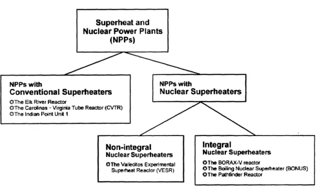
2.1 Categorization of the Superheat Nuclear Power Plants
Figure 2-1 shows the general categorization of the superheat nuclear power plants (NPPs). Superheating can be incorporated in nuclear power plants by the addition of either a nuclear or fossil fuel-fired superheater. In Figure 2-1, a conventional superheater means it is fired by fossil fuels or other non-nuclear means. Nuclear superheaters can be further categorized into two types: (a) the separate or non-integral nuclear superheater and (b) the integral nuclear superheater [8]. The non-integral nuclear superheater is namely a steam-cooled reactor. It only adds superheat to steam and the steam coolant is supplied from other sources, such as a light water reactor (LWR) or fossil power plant. For the integral nuclear superheater, steam is generated and superheated by using the same core.
Superheat and Nuclear Power Plants
(NPPs)
NPPs with NPPs with
Conventional Superheaters Nuclear Superheaters
OThe Elk River Reactor
OThe Carolinas - Virginia Tube Reactor (CVTR) OThe Indian Point Unit 1
Non-integral Integral
Nuclear Superheaters Nuclear Superheaters OThe Valecitos Experimental OThe BORAX-V reactor
Superheat Reactor (VESR) OThe Boiling Nuclear Superheater (BONUS) OThe Pathfinder Reactor
Although the reactor design will be more complicated, it is believed that the integral nuclear superheater is more cost-effective than the separate one because it needs only one core and one reactor pressure vessel to produce superheated steam.
In addition to water, the integral nuclear superheater can also be cooled by other coolants, such as organic fluid, helium, carbon dioxide, molten salt or liquid metal, and use a heat exchanger to generate superheated steam. A comprehensive review of these superheat reactor concepts has been documented in the literature [45]. However, a gas-cooled or liquid-metal-cooled reactor is not within the scope of this work. In order to take advantage of the abundant experience from today's LWRs, as well as improve the LWR technology, this work is focused on the design of an integral nuclear superheater cooled by water and steam.
2.2 Comparison between Conventional and Nuclear Superheaters
During the 1960s, when the thermal efficiency and reliability of LWRs were still poor, a few nuclear power plants with secondary superheating by means of fossil fuels were constructed (i.e. Indian Point 1 in USA, Garigliano in Italy and Lingen in Germany) [23]. However, at that time the performance of the combined cycle was not good, due to low
capacity factors and material failures [24, 25].
Nowadays, the technology of thermal power plants, both nuclear and conventional, is much more reliable (> 90% capacity factors for LWRs and 80% for coal plants). As a result, it is reasonable to reconsider the feasibility of combined advanced cycles that produce vapor by means of nuclear power - taking advantage of the lower heating costs - and superheat the secondary flow by means of fossil fuels, such as oil or gas.. Recently, economics of the combined nuclear-gas power cycle have been reevaluated [23, 26]. Results of these studies indicate that the combined nuclear-gas power cycle has possibilities to successfully compete in the near future electric market [23].
economic viability, there are still some problems and issues that need to be taken into consideration. A detailed comparison between nuclear and fossil fuel-fired superheaters is provided below by listing the advantages and disadvantages of incorporating fossil fuel-fired superheaters into nuclear power plants [80].
Advantages of using fossil fuel-fired superheaters are:
1. Plenty of experience. Fossil fuels have been used for a very long time. Industry is familiar with this technology and it has satisfactory performance.
2. Less effort on plant design. Using fossil fuel-fired superheaters can save time and effort on the plant design since a steam-cooled nuclear reactor (a separate nuclear superheater) and a complex design of an integral nuclear superheater can be avoided.
3. No neutronic control and operating problems. Compared with nuclear power superheaters, fossil-fueled superheaters are relatively simple and would not have neutronic control and operating problems.
4. Less radioactive waste. The amount of radioactive waste would be reduced if the fossil fuel-fired superheaters are used.
5. Reduced burden on plant licensing. Using fossil fuel-fired superheaters may expedite the plant licensing process compared with using a separate or integral nuclear superheater.
Disadvantages of using fossil fuel-fired superheaters are:
1. Emission of carbon dioxide. Fossil fuel-fired superheaters will definitely emit CO2 and lead to the aggravation of global warming.
2. Siting problem. Selecting an appropriate plant site will become very difficult if fossil fuel-fired superheaters are used. For nuclear power plants, a preferable plant site would be a sparsely populated area with stable weather and geological histories. However, when determining a site for fossil-fueled plants, it is always most desirable to have the site be as close as possible to the source of fuel. Conflicts may occur if we have to consider all the above issues.
3. Expanded personnel. The fossil fuel-fired superheater is a departure from nuclear power and would require two different lines of operators. Personnel cost may increase due to two different lines of technical support and maintenance.
4. Capacity loss in case of component failure. When a reactor is used for generating steam in conjunction with a fossil fired superheater, the superheater operating difficulties will impact the plant capacity factor. A failure of the superheater or any other components may require the entire plant to be shut down until the failure is repaired.
5. No contribution to nuclear technology. Today, our world is facing the not only the global warming problem but also an energy crisis. Nuclear energy has been recognized as one of the most promising means to solve these problems. Incorporating fossil fuel-fired superheaters into nuclear power plants apparently does not contribute much to nuclear technology.
In part because of the greenhouse effect, the primary objective of this work has been set to design a highly efficient reactor which could produce superheated steam by means of only nuclear energy. Therefore, fossil fuel-fired superheaters are not studied in this work. Furthermore, this work is particularly focused on the design of an integral nuclear superheater, since it has been regarded as more cost-effective and more challenging than the design of a steam-cooled reactor.
2.3 General Approaches on the Design of an Integral Nuclear
Superheater
2.3.1 Key questions for the design
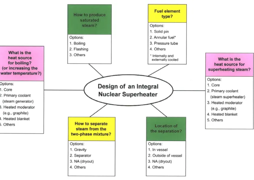
Designing a reactor with an integral nuclear superheater is a very challenging task. The layout of the core is usually much more complicated than that of a typical LWR core, which provides only boiling or heating of the primary coolant. In addition, many design margins of a LWR are reduced when the design is for an integral nuclear superheater. For example, the available space in the reactor vessel is further limited because more components related to superheating are expected to be integrated in the reactor vessel. Moreover, additional constraints will be applied to the design because of the elevated steam temperature and tougher operating conditions. Particularly, the fuel performance under superheating conditions is the most important issue to be addressed.
A successful design hinges on the designer's knowledge, experience and creativity. There are no guidelines or standard procedures for a design to start from; however, some general requirements do exist which must be met prior to further analysis. For the design of a nuclear reactor, the general considerations are safety, meeting the reactor physics, thermal-hydraulics, structural and material constraints, operation of the reactor and economic competitiveness. On the other hand, there are also some key questions for developing a reactor which has specific purposes or characteristics. In Figure 2-2, several key questions for the design of an integral nuclear superheater are listed. It should be noted that these questions are connected by multiple arrows because they are often asked iteratively in the course of the design.
A brief discussion of these key questions is provided below:
Production of the saturated steam
flashing. Boiling is widely adopted by the existing LWRs for generating saturated steam. The performance of steam production is reliable, either by means of direct boiling in the core (BWRs) or a steam generator (PWRs). Flashing or flash evaporation is well adopted by the geothermal power plants to produce saturated steam. The flash steam is formed when a heated liquid stream suddenly undergoes a reduction in pressure.
Flashing has not been used by LWRs due to the potential water-hammer hazards in the piping, low exergy efficiency in steam production [27-28] and other reasons. However, it might be worthwhile to reevaluate the feasibility of applying a flash evaporator to an integral nuclear superheater. An illustration of producing steam by flashing for an integral nuclear superheater can be found in the literature [29-30].
Separation
The means and location of the separation are important design features of an integral superheat reactor. There are many possibilities to perform separation. The steam can be separated from the two-phase mixture by a combination of chimney and gravity; or separator and forced circulation; or other innovative ways. The location of separation can be either in the vessel or outside of the vessel. Although the available space is quite limited, it is preferable to have the separation done in the vessel to avoid the need for additional loops and tank space, which increase the capital cost and provide a potential location for the loss of coolant accident (LOCA).
In the literature, some creative ways of performing separation have been proposed for an integral superheat reactor. For example, Ammon [31] integrated a chimney into the fuel assembly to achieve separation within the assemblies. Campbell [32] invented a device which allows steam to be separated from the two-phase mixture in fuel assemblies. Huet [33] invented a new type of fuel element which equips a helical apparatus to perform separation within each fuel rod.
On the other hand, separation may be not necessary for a specific design. Kluge [34] developed a conceptual superheat reactor, in which the water coolant is fully vaporized in
the fuel assemblies. Tower [35] suggested a pressure tube type integral nuclear superheater. The feedwater enters each pressure tube and is heated continuously during a plurality of passes till converting into superheated steam.
Heat source for boilingz and superheatinlr
The arrangement of heat for boiling (or increasing the water temperature if flashing is adopted for steam production) and superheating defines the main direction of the design. The fission energy generated in the core can be manipulated in many ways to boil the water coolant and superheat the formed steam. For example, an addition of a secondary system may be used for both boiling and superheating. Table 2-1 provides a matrix to distinguish the different arrangements of heat addition. Form the author's perspective, this might be a good initial question for a designer to start his/her work.
Selection of the fuel element type
After the heat sources have been arranged for boiling and superheating, one should contemplate which type of fuel element is more compatible with the design. The common options of the fuel element are (a) solid pin; (b) annular fuel which can be cooled internally and externally and (c) pressure tube. Other innovative fuel elements may also be applied.
2.3.2 Introduction of Direct and Indirect Heating Approaches
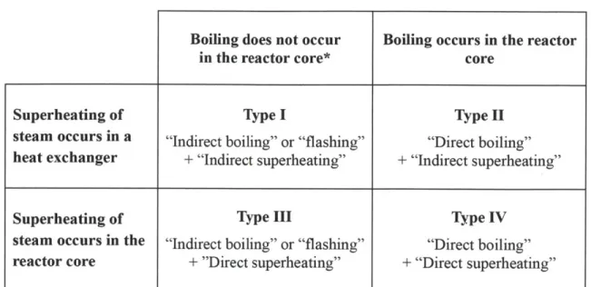
The current LWRs can be generally categorized into two types: (a) indirect boiling - if the feedwater does not boil in the core, such as PWRs; or (b) direct boiling - if boiling takes place in the core, such as BWRs. Similarly, the integral nuclear superheaters can also be categorized into two types: indirect superheating and direct superheating. As shown in Figure 2-3, the former approach uses means other than directly contacting the core to superheat steam while in the later approach steam is superheated directly in the core.
Table 2-1 Matrix of the direct and indirect heating approaches
Boiling does not occur in the reactor core*
Boiling occurs in the reactor core
Superheating of Type I Type II
steam occurs in a "Indirect boiling" or "flashing" "Direct boiling" heat exchanger + "Indirect superheating" + "Indirect superheating"
Superheating of Type III Type IV
steam occurs in the "Indirect boiling" or "flashing" "Direct boiling" reactor core + "Direct superheating" + "Direct superheating" *Producing saturated steam by flashing is considered as Type I or Type III in this matrix
Superheated steam Saturated steam
[
Indirect Superheating
]
Saturated steam[
Direct Superheating
I
Superheated steam Alternative heat sourceThe design of an integral nuclear superheater is flexible in terms of the options for heating. As shown in Table 2-1, there are four combinations, of types, for designers to contemplate their work. In the literature, all these four types of integral nuclear superheaters have been proposed. The indirect and direct superheating approaches are discussed in detail in the following sections.
2.3.3 Indirect Superheating Approach
The primary advantage of the indirect superheating approach is to avoid the interaction between steam and the core, which may simplify the core arrangement and provide easiness for the neutronic design. If steam is superheated in the core, usually there is no sufficient moderation in the superheating region of the core and compensating means, such as water rods, have to be implemented. On the other hand, the indirect superheating approach requires the core to first heat up an intermediate heat transmission element, and then let the element transmit the energy to steam. The plant efficiency may be lowered due to these additional heat exchanges.
In the literature, many alternative methods have been proposed to indirectly superheat the steam coolant. Some of these ideas are not practical for now but may become possible in the future when advanced technologies are developed. Gas-cooled and liquid-metal-cooled reactors are not discussed below because they are not within the scope of this work.
The Type I Design
Metcalf [29] invented an integral nuclear superheater which employs a plurality of tubes or conduits formed of a highly neutron absorbent material, such as boron steel alloy, to superheat steam. The steam flows upwardly through the tubes and is superheated. As described in Metcalf's work, the tubes are supposed to be heated to a relatively high temperature by nuclear reaction, resulting from a continuation of neutron bombardment.
Wigner [30] proposed a superheat reactor which is graphite moderated and produces saturated steam by flashing. The saturated steam is then conveyed through a line into a steam inlet header. The header is connected to a plurality of steam tubes of any suitable material, such as stainless steel or beryllium having a relatively small neutron capture cross section. The steam is conveyed upwardly through the tubes, which pass through the neutron moderator. Thus, the steam passing through the tubes is superheated by heat developed within the graphite moderator as the result of the nuclear fission chain reaction.
Hackney [38] developed a reactor which uses a large heat exchange system to perform both boiling and superheating. A pressurized organic liquid is chosen as the primary coolant on account of its low vapor pressure, which allows the primary coolant to remain in liquid phase under high temperature conditions without considerably raising the pressure of the primary coolant. The secondary coolant (feedwater) flows into the annular region of the heat exchange system where it is allowed to boil. The two-phase mixture is separated by the cyclone steam separators. The separated steam then flows through the inner zone of the heat exchange system where it is superheated.
The Type II Design
Bryan [36] designed a reactor which utilizes a plurality of fertile material elements arranged in a closed blanket chamber which longitudinally embraces the core. Means are provided for generating steam from the heat released in the core and the steam is superheated by the heat released in the fertile material of the blanket. The fertile material and fuel elements are arranged to be interchangeably positioned and their position is programmed in respect to time of exposure in the reactor so that the percentage of heat absorbed in the blanket compared to the heat given up in the core is a substantially constant ratio over a long period of operation.
steam generator and a steam superheater. The high pressure primary coolant first flows through the steam superheater to heat the steam coolant and then flows through the steam
generator to vaporize the feedwater.
2.3.4 Direct Superheating Approach
The direct superheating approach has been attempted many times in the past. All the integral nuclear superheaters constructed during the 1950s and the 1960s were based on the direct superheating approach. The main advantage of this approach is to directly use the fission energy to superheat steam. Since the fuel elements have the highest temperature within the reactor, the steam coolant can be superheated to a higher temperature level than the indirect superheating approach can offer. In other words, the superheated steam can have a higher temperature, thus higher plant efficiency, if the direct superheating approach is adopted.
However, the direct superheating approach also complicates the design because the steam coolant is a poor moderator. Alternative means have to be implemented to achieve a fairly thermal spectrum. In addition, control problems and a positive temperature reactivity coefficient may be incurred when the coolant and moderator are separated. If boiling and superheating both take place in the core (i.e., Type IV in Table 2-1), the design becomes more challenging. Insulation between the boiling and superheating regions, an uneven neutron spectrum across the core, and a reactivity insertion accident due to water flooding into the superheating region are the major concerns for a Type IV design.
The Type IH Design
A representative of the Type III design (indirect boiling, direct superheating) is a pressure tube superheat reactor proposed by Russia in 1958 at the second United Nations international conference on the peaceful uses of atomic energy [20]. The Russian superheat reactor is moderated by graphite and cooled by light water (the primary coolant)
and steam. The reactor core is divided into two parts, one part for heating the primary coolant and the other part for superheating steam. The primary coolant is heated in the designated part of the core, and then flows through the steam generator where the secondary coolant, which is also light water, is allowed to boil. The saturated steam produced in the steam generator is separated from the two-phase mixture in the separator and then directed into the other part of the core for superheating. More details about the Russian superheat reactor are given in Appendix A.
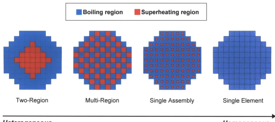
The Type IVDesign
For the Type IV design (direct boiling, direct superheating), usually the reactor core is divided into two or more regions for boiling and superheating, respectively. In the literature, there are four general concepts to configure the core: (a) two-region; (b) multi-region; (c) single assembly and (d) single element.
![Table 2-5 Design characteristics of the nuclear power plants with superheat (1/2) [13, 18, 21, 45, 50, 60]](https://thumb-eu.123doks.com/thumbv2/123doknet/14449014.518283/53.1188.106.1058.148.651/table-design-characteristics-nuclear-power-plants-superheat.webp)