Compact optical transmitters for CubeSat
free-space optical communications
The MIT Faculty has made this article openly available.
Please share
how this access benefits you. Your story matters.
Citation
Kingsbury, R. W., et al. "Compact Optical Transmitters for CubeSat
Free-Space Optical Communications." Proceedings Volume 9354,
Free-Space Laser Communication and Atmospheric Propagation
XXVII, 7-12 February, 2015, San Francisco, California, edited by
Hamid Hemmati and Don M. Boroson, SPIE, 2015, p. 93540S. © 2015
SPIE.
As Published
http://dx.doi.org/10.1117/12.2080122
Publisher
SPIE
Version
Final published version
Citable link
http://hdl.handle.net/1721.1/115239
Terms of Use
Article is made available in accordance with the publisher's
policy and may be subject to US copyright law. Please refer to the
publisher's site for terms of use.
PROCEEDINGS OF SPIE
SPIEDigitalLibrary.org/conference-proceedings-of-spie
Compact optical transmitters for
CubeSat free-space optical
communications
R. W. Kingsbury, D. O. Caplan, K. L. Cahoy
R. W. Kingsbury, D. O. Caplan, K. L. Cahoy, "Compact optical transmitters for
CubeSat free-space optical communications," Proc. SPIE 9354, Free-Space
Laser Communication and Atmospheric Propagation XXVII, 93540S (16
March 2015); doi: 10.1117/12.2080122
Compact Optical Transmitters for
CubeSat Free-Space Optical Communications
∗R.W. Kingsbury
a, D.O. Caplan
b, K.L. Cahoy
aa
Massachusetts Institute of Technology, 77 Massachusetts Ave, Cambridge, MA 02139;
bMIT Lincoln Laboratory, 244 Wood Street, Lexington, MA 02420
ABSTRACT
We present the results of an architectural trade study and prototype implementation of an optical transmitter suitable for resource-constrained CubeSats. Recent advances in CubeSat attitude determination and control systems have made it possible to achieve three-axis stabilization. This is essential for laser communications systems, which have challenging pointing and stability requirements. Our downlink terminal design fits in a 10 cm × 10 cm × 5 cm volume, uses < 10 W of power, weighs < 1 kg, and supports data rates up to 50 Mbps. The terminal incorporates pointing, tracking and acquisition optics, an optical fine-steering mechanism, and a compact transmitter. This work focuses on the development of the transmitter for the Nanosatellite Optical Downlink Experiment (NODE). Two transmitter architectures were considered initially: direct modulation of a high-power laser diode and a master oscillator power amplifier (MOPA). The MOPA-based approach was selected and a prototype “breadboard” was built from commercially available components. The prototype transmitter produces high fidelity (extinction ratio, ER > 33 dB) pulse position modulation (PPM) waveforms at 1550 nm with 200 mW average output power while consuming 6.5 W of electrical power.
Keywords: free-space optical communications, CubeSat, small satellites, optical transmitters, lasercom
1. INTRODUCTION
Nanosatellites such as CubeSats are the fastest growing class of spacecraft: approximately 300 have been launched
since 2000 and of those, approximately 150 were launched between 2013 and 2014.1 Low-cost launch
opportu-nities via “ride shares” and short development schedules have made these spacecraft attractive for educational, commercial, and military users. CubeSats are built to a common mechanical specification which defines “1U” as 10 cm × 10 cm × 10 cm, however, many developers prefer 3U designs which offer a good balance between launch cost and size, weight and power resources (30 cm × 10 cm × 10 cm, 4.0 kg, 10 W to 35 W orbit average power).
Communication bottlenecks, particularly in the downlink direction, are a common problem for many CubeSat developers. Radio frequency solutions have poor link efficiency (joules per bit) and often carry complex regulatory
burdens. Recent advances in CubeSat attitude control systems,2, 3 are beginning to address the pointing and
stability requirements of narrow beam optical communications.
Commercially available CubeSat radio frequency (RF) solutions can currently provide megabit class user
downlink rates while consuming roughly 10 W of electrical power.4, 5 The capabilities of these RF systems, along
with the state of CubeSat attitude control, ±5◦ (3-σ) , drove the requirements definition for our CubeSat-scale
lasercom system: the Nanosatellite Optical Downlink Experiment (NODE).6For the NODE terminal design, we
have budgeted 10 cm × 10 cm × 5 cm, < 1 kg and < 10 W of size, weight and power (SWaP) while delivering a user data rate of 10 Mbps to 50 Mbps. This represents a full order of magnitude improvement over existing
high-rate RF systems with similar SWaP (e.g., L3 Cadet Radio Modem4). An additional design requirement is to use
low-cost, commercial off-the-shelf (COTS) components where possible. CubeSats typically have short missions (< 1 year) in low Earth orbit (LEO) where it is possible to use low-cost approaches (e.g., COTS components) with minimal risk given the relatively benign radiation and thermal environment.
∗The Lincoln Laboratory portion of this work is sponsored by the Assistant Secretary of Defense for Research & Engineering under
Air Force Contract #FA8721–05–C–0002. Opinions, interpretations, conclusions and recommendations are those of the author and are not necessarily endorsed by the United States Government.
Send correspondence to R.W. Kingsbury (ryan.kingsbury (at) gmail.com)
Free-Space Laser Communication and Atmospheric Propagation XXVII, edited by Hamid Hemmati, Don M. Boroson Proc. of SPIE Vol. 9354, 93540S · © 2015 SPIE · CCC code: 0277-786X/15/$18 · doi: 10.1117/12.2080122
2. TRANSMITTER TRADE-STUDY
Initially, we performed a radiometric link budget analysis was used to estimate the optical transmit power
needed to achieve the desired 10 Mbps link.6 The link budget study assumed a variety of constraints facing the
CubeSat-scale implementation. Most notably: the expected pointing capability of the NODE terminal (which sets the downlink beam divergence to 2.1 mrad full width at half maximum, FWHM), the link range (< 1000 km) and the sensitivity of the ground receiver (1000 photons-per-bit, allowing for COTS detectors such as avalanche photodiode / transimpedance amp modules). Based on a preliminary set of assumed link parameters, we found that approximately 1 W of optical transmit power was needed to close the link at a 10 Mbps user data rate in the receiver thermal-noise-limited system.
We identified two candidate 1 W optical sources: a high power laser diode (HPLD), such as a “pump” laser at
980 nm, and a master-oscillator power amplifier (MOPA) design incorporating a fiber amplifier at either 1µm or
1.55µm. We assessed the effectiveness of each of these configurations for our system by considering the end-to-end
link performance. This performance analysis incorporated realistic transmitter assumptions (e.g., modulation type) and receiver parameters (e.g., suitable detector technologies for a given transmitter wavelength). System parameters were matched where possible, but the resulting transmitter capabilities did not allow for all system parameters to be matched (Table 1).
Table 1. Summary of the differences between the two transmitter configurations used in this trade study.
Parameter HPLD MOPA
Wavelength 980 nm 1550 nm
Transmit power (avg) 500 mW 200 mW
Modulation on-off-keying (OOK) PPM-16
Receiver bandwidth Per modulation requirements
Detector Si APD/TIA InGaAs APD/TIA
Performance limiter Modulation bandwidth of HPLD Wall-plug power
2.1 High-Power Laser Diode (HPLD) Transmitter
The HPLD configuration (Figure 1) consists of a directly modulated high-power laser, such as a 980 nm “pump” laser diode, which are available in convenient single mode fiber-coupled butterfly packages. The electrical-to-optical (EO) conversion efficiency of these lasers is excellent, typically greater than 30%. Operation at 980 nm is also advantageous from a receiver perspective as silicon detectors are near their peak responsivity.
980 nm Pump Laser Fiber to collimation optics High-current driver circuit 30% EO eff. 27 dBm (avg.) Power Conditioning (DC/DC conv.)
50% efficiency (estimate) 3.3 W total
Figure 1. HPLD configuration block diagram.
The principle disadvantage of the HPLD stems from the limited modulation bandwidth and associated driver circuitry, which must modulate large drive of currents. Assuming on-off-keying (OOK), which minimizes
modu-lation bandwidth relative to data rate, and a typical pump diode efficiency (η = 0.6 W A−1), the driver circuit
would need to switch over 1.5 A at 10 MHz rates. This approach is feasible, and is used in some systems (e.g. laser video projection systems), but is fundamentally limited by the package parasitics of the laser. Nevertheless, this configuration could be well within power budget: 3.3 W estimated of 8 W budget and could operate with an estimated wall-plug efficiency of 15%.
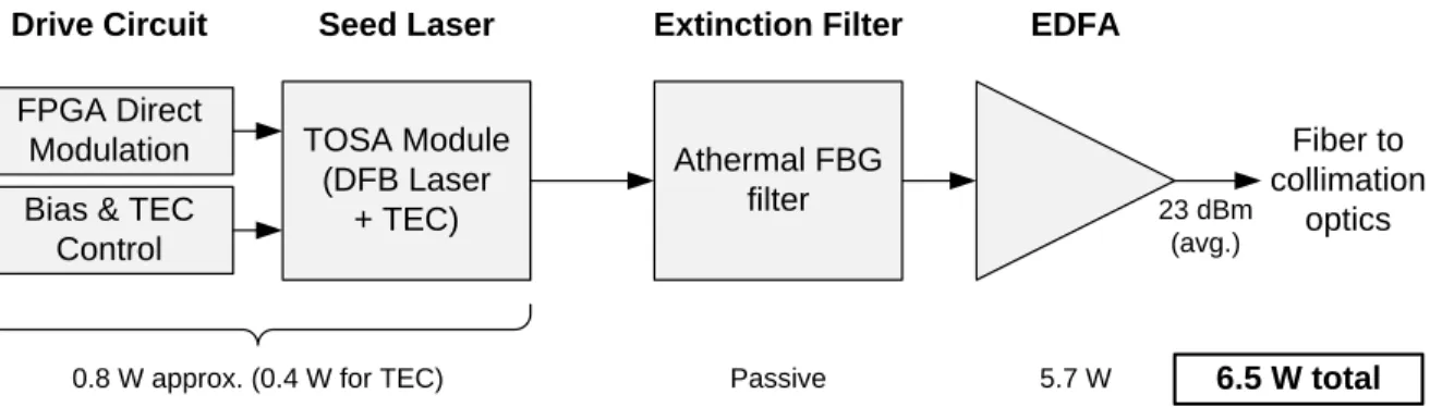
2.2 Master Oscillator Power Amplifier (MOPA) Transmitter
The MOPA configuration (Figure 2) relies on an average-power-limited fiber amplifier such as an Erbium-doped fiber amplifier (EDFA). Average-power-limited amplification allows the system to take advantage of low duty-cycle waveforms with high peak-to-average ratios such as pulse position modulation (PPM). The widespread use of fiber amplifiers in the commercial telecommunications industry is supported by a wide selection of vendors offering high-reliability components.
TOSA Module (DFB Laser + TEC) Fiber to collimation optics EDFA 23 dBm (avg.) Seed Laser FPGA Direct Modulation 5.7 W 0.8 W approx. (0.4 W for TEC) Passive
Drive Circuit
6.5 W total
Athermal FBG filter
Extinction Filter
Bias & TEC Control
Figure 2. MOPA configuration block diagram.
We considered both Yttrium-doped fiber amplifiers (YDFA, 1.05µm) and Erbium-doped fiber amplifiers
(EDFA, 1.55µm) for use in this application. Although YDFAs can provide roughly twice the wall-plug efficiency
of EDFAs, these efficiency levels are hard to find at the low (< 1 W) power levels with sufficiently compact packaging among COTS offerings from vendors. Additionally, YDFAs are less eye-safe and are generally much less available than EDFAs, making them less suitable for this COTS-based design approach. For the trade study, we baselined a 200 mW “MSA” (multi-source agreement) form-factor EDFA that is compatible with the volume constraints of CubeSats. The lower output power of the MOPA (relative to the HPLD) is roughly balanced by the link margin gain benefit from moving to PPM from OOK modulation on the average-power-limited EDFA.
Aside from the amplifier, the modulator is typically a large power consumer for low-SWaP MOPA designs. For PPM waveforms, this modulator must provide high extinction ratios (ER) in order to avoid “power robbing”
losses in the fiber amplifier (e.g. for PPM-16, ER > 27 dB7). To avoid the power penalty associated with
an external modulator, a direct modulation approach was selected. The transmitter digital electronics (e.g. an FPGA) directly modulate the seed laser with the communication waveform. Only ∼ 10 dB of ER can be expected
from direct moduation if the laser is kept above threshold (ith), which is necessary for wide-band modulation.8–11
To further improve ER, the laser’s adiabatic frequency chirp8 is used in conjunction with a narrow bandpass
filter to produce FM-to-AM conversion. This technique has been demonstrated in both fiber9, 10and free-space11
applications.
The MOPA design is estimated to consume 6.5 W yielding a wall-plug efficiency of approximately 3%, driven largely by the power efficiency of the COTS EDFA. This is much lower than the HPLD design, but the MOPA is capable of producing higher fidelity waveforms at much faster modulation rates (> 1 GHz).
2.3 Selection Criteria
Table 2 gives a high-level comparison for the two transmitter architectures. From a size, weight and power perspective, the HPLD is the clear winner but the design suffers from fundamental modulation bandwidth restrictions. Presently, our system data rates are primarily limited by available CubeSat power and relatively broad transmit beamwidth (2.1 mrad FWHM) derived from CubeSat pointing capabilities. Pointing performance should improve in the coming years which will allow for narrower transmit beams and, as a result, faster data rates. Although the MOPA has higher SWaP, it remains within budget and can be constructed using readily available COTS components. Furthermore, it has the added benefit of being able to scale to these higher rates.
Table 2. Comparison of transmitter architectures Parameter HPLD MOPA Wavelength 980 nm 1550 nm Approx. Size 5 cm × 5 cm × 1 cm 10 cm × 10 cm × 3 cm Approx. Mass 100 g 250 g Approx. Power 3.3 W 6.5 W
Max Modulation Bandwidth < 50 MHz (package parasitics) > 1 GHz
Peak-to-average Limit Low (typ. < 10) High (> 16)
Spectral Quality Poor (> 1 nm) Excellent
Notable Risks Driver circuit design Wall-plug power
Spectral quality Achieving high ER
3. DETAILED DESIGN & PERFORMANCE VALIDATION
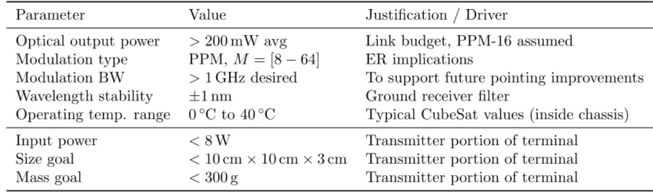
Table 3 summarizes the detailed design requirements for the transmitter subsystem of the NODE terminal. Power consumption is the most significant constraint facing the transmitter design which motivated validation of vendor power consumption specifications.
3.1 FPGA Modulator
The NODE terminal will include an FPGA to generate the communications waveform. For initial laboratory testing, we have configured a Xilinx Spartan 6 evaluation board to produce pulse position modulation (PPM)
waveforms. Both the PPM slot rate (fslot) and the modulation order (M ) can be configured in realtime. A
general purpose I/O pin, configured as a 2.5 V single-ended output, is used to directly modulate the seed laser. The seed laser interface consists of an impediance matching network and an AC-coupling capacitor. Unlike many other high-rate FPGA modulators, we do not make use of power-hungry Gigabit transcievers (e.g. RocketIO) in this design. Instead, the design relies on the low-power serializer-deserializer functionality built into the FPGA’s I/O buffers. These SERDES allow operation at up to 600 MHz while maintaining much lower FPGA fabric clock
rates. When generating a PPM-16 waveform at fslot = 200 MHz, the FPGA is able to deliver 50 mA of drive
into a 50 Ω load. This PPM slot rate was chosen because it allows the design to achieve the desired link rates
while staying well above the diode’s thermal chirp crossover point.8
3.2 Seed Laser
The primary selection criteria for the seed laser was the power consumption of the integrated thermoelectric cooler (TEC). Accurate temperature control is necessary to stabilize the laser wavelength, and on many lasers the TEC requires significant amounts of power (> 1 W). The size and mechanical mount style were secondary selection cri-teria. Transmitter optical sub-assemblies (TOSA) were identified as a good match for our application: they have low power TECs (< 0.4 W) and are available in very compact fiber-coupled packages (20 mm × 8 mm × 5 mm). The TOSA selected for this design has 6 dBm CW output power in the 1550 nm C-band.
Table 3. Transmitter design requirements
Parameter Value Justification / Driver
Optical output power > 200 mW avg Link budget, PPM-16 assumed
Modulation type PPM, M = [8 − 64] ER implications
Modulation BW > 1 GHz desired To support future pointing improvements
Wavelength stability ±1 nm Ground receiver filter
Operating temp. range 0◦C to 40◦C Typical CubeSat values (inside chassis)
Input power < 8 W Transmitter portion of terminal
Size goal < 10 cm × 10 cm × 3 cm Transmitter portion of terminal
20 40 60 80 100 120 140 DC Laser Bias (iDC, mA)
0.0 0.2 0.4 0.6 0.8 1.0 1.2 W av ele ng th ( λ , n m )
+1.548e3 Wavelength Tuning (I&T)
20◦C 22◦C 24◦C 26◦C 28◦C 30◦C
Figure 3. Seed laser temperature and DC current wave-length tuning relationships.
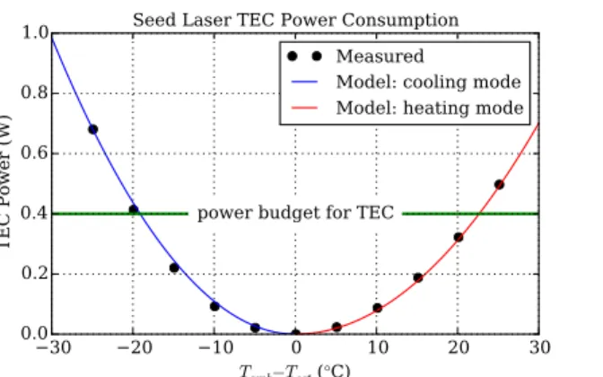
30 20 10 0 10 20 30 Tamb−Tset (°C) 0.0 0.2 0.4 0.6 0.8 1.0
TEC Power (W) power budget for TEC
Seed Laser TEC Power Consumption Measured
Model: cooling mode Model: heating mode
Figure 4. Seed laser TEC power consumption versus dif-ference from ambient temperature.
An automated testbed consisting of a laser diode controller, a wavemeter and an optical spectrum analyzer was used to characterize the tuning parameters of the seed laser (Figure 3). These tuning parameters form the basis for aligning the laser with the desired communications wavelength. The approximate tuning characteristics for a
representative device were ∆λ/∆T = −11 GHz/◦C, ∆λ/∆iDC = −0.45 GHz/mA, and ∆λ/∆iAC= 0.20 GHz/mA
(measured with PPM-16 at fslot = 200 MHz). Although undesirable in most TOSA applications (e.g., WDM
systems), we use the laser’s AC wavelength “chirp” (∆λ/∆iAC) in our design.
The TOSA’s TEC power consumption was validated by measuring both VT EC and iT EC while the setpoint
(Tset) was swept relative to ambient. Figure 4 shows the measured power consumption as well as quadratic
models for both heating and cooling modes. TEC power consumption was within the 0.4 W budget across the
expected operational range for the device (0◦C to 40◦C). An item for future investigation is the efficiency of the
TEC driver circuit which will likely be based upon an laser diode controller IC.
3.3 Extinction Filter
The extinction filter is used to improve the ER of the seed laser signal through FM-to-AM conversion. Align-ment between the seed laser wavelength and the filter passband is necessary to simultaneously achieve high ER and low insertion loss. Athermal fiber Bragg grating (FBG) filters can provide both steep transition re-gions ( 1 dB/GHz) and high stopband attenuation (> 30 dB) along with a thermally stable center wavelength
(∼ 100 MHz/◦C). A temperature sensor mounted to the FBG filter will be used to compensate for the slight
thermal dependency of the FBG filter. The overall wavelength shift of the transmitter (∼ 4 GHz over full tem-perature range) during this compensation is acceptable since the ground station receiver optical filter bandwidth
is 250 GHz (or 2 nm at 1.55µm). 20 10 0 10 20 Frequency (GHz) 50 40 30 20 10 0 Insertion Loss (dB) space mark
Normalized Insertion Loss
5 GHz 10 GHz
Figure 5. Passband comparison of 5 GHz and 10 GHz filters with approximate laser center wavelengths (red).
50 40 30 20 10 0 Duty Cycle (dB) 50 40 30 20 10 0
Normalized Average Power (dB)
Extinction Ratio Measurement
fslot=200 MHz fslot=40 MHz ER=10 dB ER=20 dB ER=30 dB ER=40 dB ER=50 dB ER=∞
Figure 6. Extinction ratio theoretical curves and measured results using duty cycle sweep.
Figure 5 compares the insertion loss of two Gaussian passband FBG filters considered for this application
along with the expected wavelength “chirp” (∆λ/∆iAC) of the seed laser. The 10 GHz chirp shown in the figure
was achieved with 50 mA of direct drive from a Xilinx Spartan 6 LVCMOS I/O pin. The narrower 5 GHz FBG filter was able to produce sufficient (> 33 dB) seed suppression while maintaining low insertion loss.
A swept duty-cycle ER measurement12 showed that the combined seed laser plus extinction filter achieved
an ER of > 33 dB (Figure 6) at fslot = 200 MHz. This ER is sufficient for low duty-cycle waveforms such as
64-ary PPM. The same measurement was completed at fslot = 40 MHz which showed a slightly degraded ER
(∼ 28 dB). This is due to fact that the modulation frequency is closer to the transition point where thermal
effects begin to dominate charge carrier density effects.8 For the purposes of the NODE program, we will operate
the transmitter at fslot≥ 200 MHz and vary the modulation order (M ) to achieve a variety of link rates.
3.4 Optical Amplifier
Erbium-doped fiber amplifiers (EDFAs) are widely available due to their use in the telecommunications industry. Because of the budgetary constraints facing most CubeSat programs, it was desirable to select a low-cost, mass-produced EDFA. The industry standard MSA form-factor is ideal for CubeSat applications as its size (9 cm × 6 cm × 1.5 cm) just fits within the 10 cm × 10 cm chassis cross-section.
MSA form-factor EDFAs are offered in a variety of power output levels and gains. We selected a higher power output variant (200 mW average optical) that fell within our electrical power budget (8 W for entire transmitter). With some minor mechanical modifications, the COTS EDFA can fit within the tight CubeSat chassis constraints.
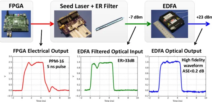
4. RESULTS AND CONCLUSIONS
Time-domain measurements show that the NODE transmitter design can produce high-fidelity optical waveforms (Figure 7). Furthermore, the > 33 dB ER of the seed laser and filter assembly allows operation at high order PPM (64-ary) without sacrificing the peak power gains offered by the average-power-limited EDFA. Since the design supports modulation bandwidths in excess of 600 MHz, it will be suitable in future systems with more capable pointing control. Finally, and most critical for our application, the power consumption of the transmitter is within budget with nearly 20% margin (Table 4).
Table 4. Transmitter power consumption summary
Parameter Value Notes
EDFA 5.7 W Manufacturer worst case specification
Seed laser TEC 0.4 W Peak power over 0◦C to 40◦C
Seed laser DC bias 0.2 W Worst case
Seed laser AC drive 0.01 W 50 mA, 1/16 duty cycle
FPGA logic 0.2 W Transmitter portion of FPGA (shared with other functions)
Total 6.51 W
Margin 1.49 W 8 W budget for transmitter
ACKNOWLEDGMENTS
Many individual and organizations have made valuable contributions to this effort. Malcolm Wright and William Farr (NASA Jet Propulsion Lab) provided valuable input early in the project during the architectural trade study. Our vendors, particularly NuPhoton and Teraxion, diligently iterated with us as we converged on the final design. Bob Schulein (MIT Lincoln Lab) assisted with automated measurement systems that significantly improved the quality of data collected for this paper. Finally, we would like to acknowledge both the NASA Space Technology Research Fellowship program and the JPL Strategic University Research Partnership program for funding this project.
REFERENCES
[1] Swartwout, M., “The first one hundred cubesats: A statistical look,” Journal of Small Satellites Vol 2, Num 2, 213–233 (2014).
[2] Bingham, B. and Young, Q., “Road to a three-axis-stabilized cubesat,” in [32nd Annual AAS Rocky Moun-tain Guidance and Control Conference ], 133, 607–613 (2009).
[3] Pong, C., Knutson, M. W., Miller, D. W., Seager, S., Lim, S., Henderson, T. C., and Murphy, S. D., “High-precision pointing and attitude determination and control on exoplanetsat,” in [AIAA Guidance, Navigation, and Control Conference ], (2012).
[4] Kneller, E., Hyer, K., McIntyre, T., Jones, D., and Swenson, C., “Cadet: A high data rate software defined radio for smallsat applications,” in [26th Annual AIAA/USU Conference on Small Satellites ], (2012). [5] Klofas, B. and Leveque, K., “A survey of cubesat communications systems: 2009-2012,” in [CalPoly CubeSat
Developers’ Workshop ], (2013).
[6] Kingsbury, R., Riesing, K., and Cahoy, K., “Design of a free-space optical communication module for small satellites,” in [Proceedings of the AIAA/USU Conference on Small Satellites ], SSC14–IX–6 (2014).
[7] Caplan, D. O., Robinson, B. S., Murphy, R. J., and Stevens, M. L., “Demonstration of 2.5 gslot/s optically-preamplified m-ppm with 4 photons/bit receiver sensitivity,” in [Optical Fiber Communication Conference ], PDP32, Optical Society of America (2005).
[8] Vodhanel, R. S., Elrefaie, A. F., Iqbal, M., Wagner, R. E., Gimlett, J., and Tsuji, S., “Performance of directly modulated dfb lasers in 10-gb/s ask, fsk, and dpsk lightwave systems,” Lightwave Technology, Journal of 8(9), 1379–1386 (1990).
[9] Lee, C.-H., Lee, S.-S., Kim, H. K., and Han, J.-H., “Transmission of directly modulated 2.5-gb/s signals over 250-km of nondispersion-shifted fiber by using a spectral filtering method,” Photonics Technology Letters, IEEE 8(12), 1725–1727 (1996).
[10] Mahgrefteh, D., Cho, P., Goldhar, J., and Mandelberg, H., “Penalty-free propagation over 600 km of non-dispersion-shifted fiber at 2.5 gb/s using a directly laser modulated transmitter,” in [Lasers and Electro-Optics, 1999. CLEO’99. Summaries of Papers Presented at the Conference on ], 182, IEEE (1999).
[11] Caplan, D. O., Carney, J. J., and Constantine, S., “Parallel direct modulation laser transmitters for high-speed high-sensitivity laser communications,” in [CLEO: Applications and Technology ], PDPB12, Optical Society of America (2011).
[12] Caplan, D., “A technique for measuring and optimizing modulator extinction ratio,” in [Lasers and Electro-Optics, 2000.(CLEO 2000). Conference on ], 335–336, IEEE (2000).