A Computer Simulation and Molecular-Thermodynamic
Framework to Model the Micellization of Ionic Branched
Surfactants in Aqueous Solution
by
Shangchao Lin
B.S., Mechanical Engineering, University of Michigan, 2006
Submitted to the Department of Mechanical Engineering
in partial fulfillment of the requirements for the degree of
Master of Science
at the
MASSACHUSETTS INSTITUTE OF TECHNOLOGY
SEPTEMBER 2008
© 2008 Massachusetts Institute of Technology. All rights reserved.
The author hereby grants to Massachusetts Institute of Technology permission to
reproduce and to distribute copies of this thesis document in whole or in part.
Signature of Author . . .
Department of Mechanical Engineering
August 21, 2008
Certified by . . .
Daniel Blankschtein
Professor of Chemical Engineering
Thesis Supervisor
Accepted by . . .
Nicolas G. Hadjiconstantinou
Associate Professor of Mechanical Engineering
Thesis Reader
Accepted by . . .
Lallit Anand
Professor of Mechanical Engineering
Chairman, Committee for Graduate Students
A Computer Simulation and Molecular-Thermodynamic
Framework to Model the Micellization of Ionic Branched
Surfactants in Aqueous Solution
by
Shangchao Lin
Submitted to the Department of Mechanical Engineering
on August 21, 2008, in partial fulfillment of the
requirements for the degree of
Master of Science
Abstract
Surfactants, or surface active agents, are chemicals exhibiting amphiphilic behavior
toward a solvent. This amphiphilic character leads to increased activity at interfaces and
to self-assembly into micellar aggregates beyond a threshold surfactant concentration,
referred to as the critical micelle concentration (CMC), in bulk solutions. As a result of
these unique attributes, surfactants are used in many pharmaceutical, industrial, and
environmental applications, including biological separations, fat metabolism during
digestion, drug delivery, and water purification. Selection of the appropriate surfactant
for a given application is often motivated by the need to control bulk solution
micellization properties, such as the CMC and the micelle shape and size. The ability to
make molecular-level predictions of these surfactant properties would allow formulators
in industry to speed up the design and optimization of new surfactant formulations.
In this thesis, a combined computer simulation/molecular-thermodynamic (CS-MT)
modeling approach was developed and utilized to study the micellization behavior of
ionic branched surfactants, which are a class of surfactants of great industrial relevance in
applications such as detergency, emulsification, and enhanced-oil recovery. In the CS-
MT modeling approach, molecular dynamics (MD) simulations are used to obtain input
parameters for molecular-thermodynamic (MT) modeling of surfactant micellization.
This approach is motivated by the limitations inherent in computer simulations (the high
computational expense associated with modeling self-assembly) and in MT modeling
approaches (their restriction to structurally and chemically simple surfactants).
One key input required for traditional MT modeling is the identification of the
hydrated (“head”) and the dehydrated (“tail”) portions of surfactants in a self-assembled
micellar aggregate. Using the results of MD simulations of surfactants in a micellar
environment, a novel head and tail identification method was developed based on the
determination of a conceptual micelle core-water interface. The introduction of an
interfacial region consisting of partially hydrated, neutral atomic groups required
formulating an improved surfactant tail packing approach.
Another key input required in the CS-MT modeling approach is the fractional
degree of hydration of each atomic group in the ionic branched surfactants considered in
this thesis, which can be used to accurately quantify the hydrophobic driving force for
micelle formation in aqueous media. Fractional hydration profiles were obtained by
conducting two MD simulations, one in a bulk water environment and the other in a
micellar environment. By investigating the radial distribution function (RDF) between
each surfactant group and hydrating atoms which are capable of forming hydrogen-bonds
and coordinate-bonds, an updated cutoff distance for counting hydrating contacts was
selected. These simulated fractional hydration profiles were then utilized as inputs in the
MT model, which enables calculation of the minimum free energy associated with
micelle formation, from which the CMC and the optimal micelle shape and size can be
predicted at the molecular level.
The MD simulations were shown to extend the applicability of the traditional MT
modeling approach to more complex surfactant systems than had been possible to date. A
rich variety of ionic branched surfactants were modeled using the new CS-MT
modeling approach, including two homologous series of simple secondary alkyl
sulfonates and three classes of more complex ionic branched surfactants possessing
aromatic moieties. For each of the ionic branched surfactants modeled, the predictions of
the CS-MT modeling approach were found to be in reasonable agreement with the
experimental data, including accounting for the chemical and structural complexities of
the branched surfactants more accurately. The CS-MT modeling approach developed in
this thesis not only extends our ability to make accurate molecular-level predictions of
the micellization behavior of complex surfactants, but it also contributes to our overall
fundamental understanding of the solution behavior of surfactants.
Thesis Supervisor: Daniel Blankschtein
Title: Professor of Chemical Engineering
Contents
1 Introduction 17
1.1 Background and Motivation . . . 17
1.2 Introduction to Theoretical Models of Surfactant Micellization . . . 22
1.2.1 Brief Overview of Theoretical Models of Micellization . . . 22
1.2.2 Limitations of the Current Molecular-Thermodynamic Modeling Approaches 23 1.3 Introduction to Computer Simulation Methods . . . 24
1.3.1 Brief Overview of Computer Simulation Studies of Micellization . . . 26
1.3.2 Introduction to Computer Simulation–Molecular-Thermodynamic (CS–MT) Models . . . 27
2 Theoretical Background 30 2.1 Traditional Molecular-Thermodynamic (MT) Model of Micellization . . . 30
2.1.1 Thermodynamic Framework . . . 30
2.1.2 Traditional MT Model of Surfactant Micellization . . . 32
2.2 The Computer Simulation–Molecular-Thermodynamic (CS–MT) Modeling Ap-proach . . . 38
2.2.1 Theoretical Framework . . . 38
2.2.2 The Degree of Hydration, fi . . . 40
2.2.3 The Free Energy of Dehydration, ^gdehydr. . . 41
2.2.4 The Free Energy of Hydration, ^ghydr . . . 42
3 Molecular Dynamics (MD) Simulations in the CS–MT Modeling Approach 46 3.1 Modeling Approach to Quantify the Degree of Hydration . . . 46
3.2 Simulation Methods and Parameters . . . 49
3.3 System Preparation and Equilibration . . . 52
3.3.1 Bulk Water Simulation . . . 52
3.3.2 Micellar Aggregate Simulation . . . 53
3.3.3 Selection of the Simulated Micelle Geometry . . . 56
3.4 Data Analysis Method . . . 58
3.4.1 De nition of Hydration . . . 58
3.4.2 Analysis of the Bulk Water and Micelle Simulation Results . . . 58
3.4.3 Cutoff Distance Selection by Analyzing Radial Distribution Functions . . . 60
3.4.4 Error Analysis in Counting Hydrating Contacts . . . 67
4 Surfactant Property Inputs Required to Implement the CS–MT Modeling Approach 69 4.1 Head and Tail Identi cations Based on Micelle Simulations . . . 69
4.1.1 Extension of the Gibbs Dividing Surface Approach . . . 70
4.1.2 Location of Atomic Group i in the Surfactant Molecule . . . 77
4.1.3 Assignment of Surfactant Neutral Groups in Addition to Surfactant Head and Tail Groups . . . 80
4.2 Estimation of Four Surfactant Geometric Parameters Based on the Head/Neutral/Tail Group Assignments . . . 82
4.3 Interfacial Tension Predictions Using Group-Contribution Methods . . . 84
5 Prediction of Degrees of Hydration and Critical Micelle Concentrations of Branched Surfactants Using the CS–MT Modeling Approach 87 5.1 Prediction of Fractional Degrees of Hydration Using Molecular Dynamics (MD) Simulations . . . 87
5.1.1 Simulated Fractional Hydration Pro les of the x-y-SAS Branched Surfactants . . . 88
5.1.2 Simulated Fractional Hydration Pro les of the Complex Ionic Branched Surfactants . . . 92
5.2 Predicting the Micellization Behavior of the x-y-SAS Branched Surfactants . . . . 95 5.3 Predicting the Micellization Behavior of the Complex Ionic Branched Surfactants . 102
6 Conclusions and Future Work 108
6.1 Thesis Summary . . . 108
6.2 Future Research Directions . . . 110
6.2.1 Frame-by-Frame Analysis of MD Simulation Results . . . 110
6.2.2 MD Simulation Studies of Solvent Accessible Surface Areas (SASA's) of Branched Surfactants . . . 111
6.2.3 Validation of Surfactant Property Predictions . . . 111
6.2.4 Improving Surfactant Head and Tail Identi cation . . . 112
List of Figures
1-1 At surfactant concentrations which exceed the CMC, surfactant monomers self-assemble in water into micellar aggregates. (Color code for the surfactant mole-cule: blue – surfactant head and red – surfactant tail). . . 18 1-2 Examples of branched surfactants: (a) branched dimethylammonium bromide (DC6AB),
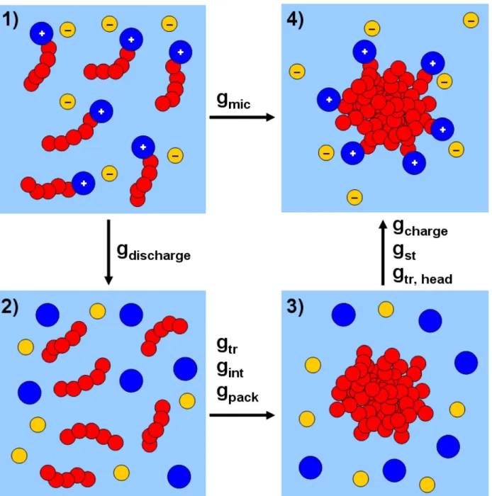
(b) sodium dialkyl benzene sulfonate, (c) alkyl pyridinium iodide, (d) Triton X-100 (left) and Silwet L-77 (right), (e) lecithin (phosphatidylcholine), and (f) arginine-based gemini surfactant. The "SC" in (a), (b), and (c) denotes side chain, and the “Me” in Triton X-100 and Silwet L-77 denotes a methyl group. . . 21 2-1 Sequence of steps followed in the molecular-thermodynamic cycle used in the
CS-MT modeling approach. This sequence is presented in the context of the micel-lization of a cationic surfactant in aqueous solution. Between frames (1) and (2), the surfactant heads (the large blue circles carrying positive charges) are separated from the surfactant tails (the chains consisting of ve red circles), and the surfac-tant heads and the counterions (the small yellow circles carrying negative charges) are discharged (as re ected in gdischarge). Between frames (2) and (3), the
surfac-tant hydrophobic tails are grouped to form the micelle core (as re ected in gtr, gint,
and gpack). Between frames (3) and (4), the surfactant heads are reattached to one
end of the surfactant tails (as re ected in gst and gtr;head), and the surfactant heads
3-1 Ionic branched surfactants modeled in this thesis. The two series of simple ionic branched surfactants include sodium secondary alkyl (paraf n) sulfonates (denoted as x-y-SAS), where in one series, the length of the primary hydrocarbon chain is kept xed (y = 9) while x = 2; 4; 6; 8; or 9, and in the second series, the total length of the two portions of the hydrocarbon chain is kept xed (x + y = 11) while x = 1; 2; 3; 4; or 5. The three classes of complex ionic branched surfactants consist of two sodium 4-(C12-alkyl) benzene sulfonates (denoted as surfactants A
and B), two sodium 2,5-dialkyl benzene sulfonates (denoted as surfactants C and D), and two 1-methyl-4-(C12-alkyl) pyridinium iodides (denoted as surfactants E
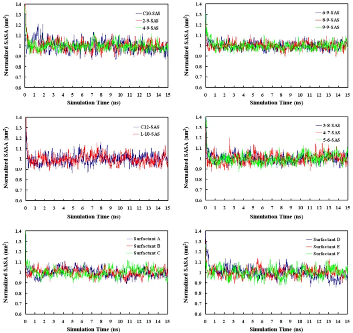
and F). . . 48 3-2 Normalized solvent accessible surface areas (SASA's) of the simulated surfactant
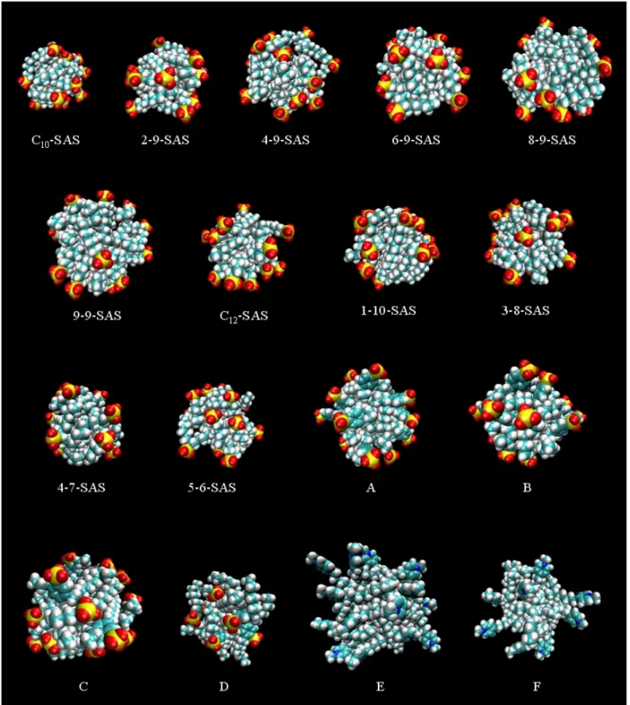
micelles as a function of simulation time during 15 ns of simulation for all the ionic linear and branched surfactants considered in this thesis. . . 55 3-3 Snapshots of the post-equilibration structures of the simulated micelles
correspond-ing to each of the ionic linear and branched surfactants considered in this thesis. For clarity, water molecules and counterions are not shown. (Color code: red – oxygen, yellow – sulfur, light blue – carbon, white – hydrogen, and dark blue – nitrogen.) . . . 57 3-4 On the left: illustration of the number RDF (the green ring region at ri) of
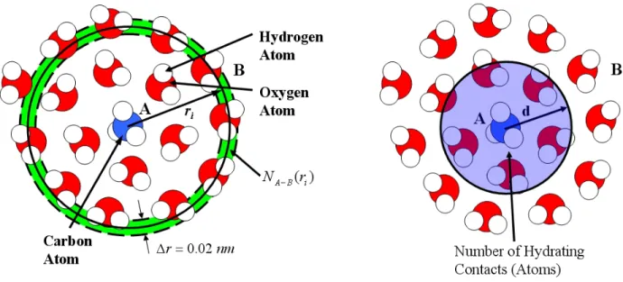
hy-drogen and oxygen atoms (the B atoms) with respect to a methyl group (the A atom), corresponding to one simulation time frame. On the right: illustration of the method used to count the number of hydrating contacts which involves count-ing the number of hydratcount-ing atoms within a cutoff distance d (that is, within the sphere of radius d). . . 62
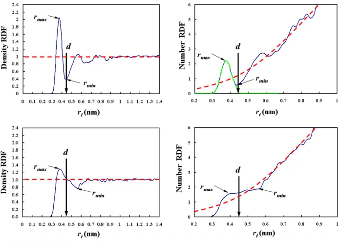
3-5 Sample density RDF's (left column) and corresponding number RDF's (right col-umn) of water oxygen atoms with respect to: (i) the sulfur atom in the hydrophilic anionic sulfonate group (top row), and (ii) the carbon atom in the hydrophobic CH3
group (bottom row). A symmetric distribution (green dashed curve) of the water oxygen atoms is depicted in the number RDF plot for the hydrophilic sulfonate group. The area under the green dashed curve represents the hydration number. The red dashed horizontal lines and curves indicate the RDF's for the bulk water environment. Note that the locations of rmax and rmin are assigned in the density
RDF plots and are also shown in the number RDF plots at the same locations. The cutoff distance d for the hydrophilic sulfonate group was determined using the two methods discussed in this section — one using the density RDF curve, and the other using the number RDF curve. As discussed in the text, the cutoff distance d for the hydrophobic CH3 group was selected to be equal to the cutoff distance d
for the hydrophilic sulfonate group. . . 64 4-1 Top left: illustration of the number RDF (the green ring region at ri) of hydrating
atoms (the light blue region and the dark blue circles) with respect to the micelle COM, corresponding to one simulation time frame. Top right: sample density RDF of hydrating atoms with respect to the micelle COM. The green dashed line rep-resents the conceptual pure hydrating atom phase. The red dashed line reprep-resents the conceptual pure micelle-core phase. The black dashed line denotes the location of the equimolar Gibbs dividing surface. Bottom left: MD simulation snapshot of an equilibrated C12-SAS micelle (color code: red – oxygen, yellow – sulfur, light
blue – carbon, white – hydrogen, and dark blue – sodium ion). The green dashed circle separates the bulk water and the micelle core–water interface phases. The red dashed circle separates the micelle core–water interface and the micelle core phases. The black dashed circle denotes the location of the equimolar Gibbs di-viding surface. Bottom right: the number RDF corresponding to the density RDF on the top right. The two grey areas represent the excess and the de ciency of hydrating atoms. . . 71
4-2 Head and tail identi cation results for the various ionic linear and branched sur-factants considered in this thesis. The horizontal black dashed lines denote l — the locations of the equimolar Gibbs dividing surfaces. The red dots denote Li,
the expected location of surfactant group i. The blue markers denote i, one
stan-dard deviation from the expected location of group i. The chemical structures of the various ionic linear and branched surfactant considered are shown below each plot, including the various group numbers (color code: red – head groups, light blue – neutral groups, and black – tail groups). . . 76 4-3 Normalized number RDF of ve representive atomic groups (S: sulfur atom in the
sulfonate group, C2, C7, C13, and C19: four carbon atoms in the hydrocarbon groups indicated by their locations in the surfactant molecule, where the chemical structure is shown in the top left corner of the RDF plot) in surfactant A with respect to the spherical micelle COM. . . 78 5-1 Simulated average fractional degree of hydration, fi, of each group i in the rst
se-ries of x-y-SAS branched surfactants (y = 9), with the chemical structures shown below the fi plots. The error bars correspond to the standard error of the mean, as
computed through block averaging of the computer simulation data (see Section 3.4.4). . . 89 5-2 Simulated average fractional degree of hydration, fi, of each group i in the second
series of x-y-SAS branched surfactants (x + y = 11), with the chemical structures below the fi plots. The error bars shown correspond to the standard error of the
mean, as computed through block averaging of the computer simulation data (see Section 3.4.4). . . 90 5-3 Simulated average fractional degree of hydration, fi, of each group i in the complex
ionic branched surfactants considered in this thesis, with the chemical structures shown below the fi plots. The error bars correspond to the standard error of the
mean, as computed through block averaging of the computer simulation data (see Section 3.4.4). . . 93
5-4 CMC's predicted using the CS–MT model (blue) and the traditional MT model (green), as well as the experimental CMC's (red), for the rst series of x-y-SAS branched surfactants (y = 9). The CMC of the C10-SAS linear surfactant is also
shown for comparison. The inset CMC plot for 8-9-SAS and 9-9-SAS is shown for clarity. Each error bar corresponds to the standard error of the mean in predicting gtr;CS M T using the CS–MT model, as reported in Table 5.3. . . 99
5-5 CMC's predicted using the CS–MT model (blue) and the traditional MT model (green), as well as the experimental CMC's (red) for the second series of x-y-SAS branched surfactants (x + y = 11). The CMC of the C12-SAS linear surfactant is
also shown for comparison. Each error bar corresponds to the standard error of the mean in predicting gtr;CS M T using the CS–MT model, as reported in Table 5.3. . . 101
5-6 CMC's predicted using the CS–MT model (blue) and the traditional MT model (green), as well as the experimental CMC's (red), for the complex ionic branched surfactants A to F. Each error bar corresponds to the standard error of the mean in predicting gtr;CS M T using the CS–MT model, as reported in Table 5.6. Note
that the CMC's predicted using the traditional MT model for surfactants A to D are nearly zero mM (see Table 5.6), and are therefore not visible on the scale used to report the CMC's. . . 105
List of Tables
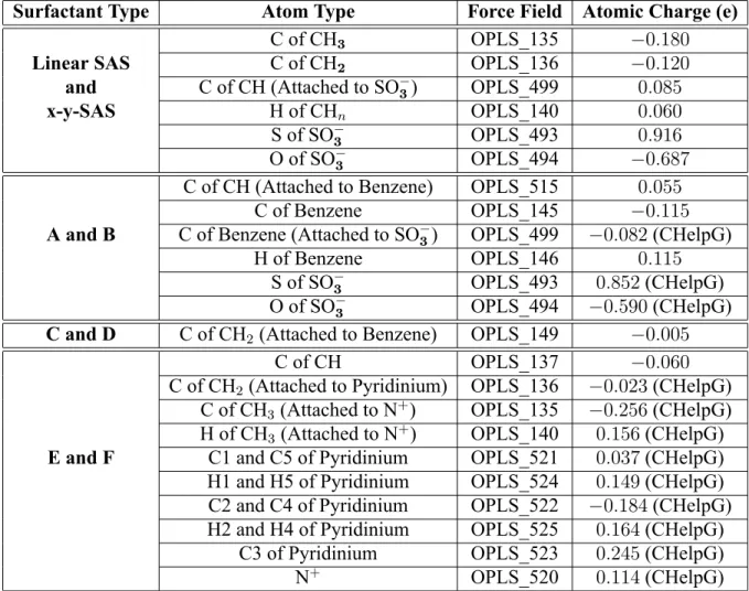
3.1 Summary of the atomic charges used to model the ionic linear and branched surfac-tants considered in this thesis. "CHelpG" in parentheses indicates that the atomic charges were computed using the QM method. The force eld parameters of CH2
and CH3 are listed just for x-y-SAS, but were used for all the other surfactant
molecules unless speci ed otherwise in parentheses. The force eld parameters listed for surfactants A and B were used for surfactants C and D as well. The carbon atoms in the pyridinium ring are denoted as C1 to C5 clockwise starting from the nitrogen atom. The hydrogen atoms in the pyridinium ring are assigned according to the carbon atoms to which they are attached. . . 51 3.2 The number of surfactant and water molecules and the total number of atoms
cor-responding to each of the simulated ionic linear and branched surfactant micelles considered. The numbers in parentheses correspond to the actual numbers of sur-factant molecules composing the micelle (see text). . . 54 4.1 The four estimated surfactant geometric parameters (ah, a0, dcharge, and lhg) and
interfacial tensions required to implement the CS-MT modeling approach. . . 84 5.1 CS-MT and traditional MT modeling results for the simulated ionic x-y-SAS branched
surfactant micelles considered in this thesis. CS-MT model predictions of ^gdehydr,
^
ghydr, ^gint, and gtr;CS M Twere made as described in Section 2.2. The uncertainties
reported for the CS-MT model predictions correspond to the standard error of the mean in predicting gtr;CS M T, as computed through block averaging of the
com-puter simulation data (see Section 3.4.4). Traditional MT modeling predictions of gtrare presented to allow comparison with gtr;CS M T. . . 96
5.2 CS-MT modeling results for the optimal ionic x-y-SAS branched surfactant mi-celles considered in this thesis. Note that the traditional MT modeling results are almost identical in this case (see the text for details). . . 96 5.3 CS-MT and traditional MT modeling results for the optimal ionic x-y-SAS branched
surfactant micelles considered in this thesis. The CS-MT and the traditional MT model predictions of the optimal gmic, denoted as gmic, were obtained using the
values of gtr;CS M T and gtr reported in Table 5.1 as inputs to Eqs. 2.5 and 2.15,
respectively. The CS-MT and the traditional MT model predicted CMC's were computed using Eq. 2.4, corresponding to the predicted gmic values. The experi-mental gmicvalues were inferred from the experimental CMC's using Eq. 2.4. The uncertainties reported for the CS-MT model predictions correspond to the standard error of the mean in predicting gtr;CS M T, as computed through block averaging
of the computer simulation data (see Section 3.4.4). . . 97 5.4 CS-MT and traditional MT modeling results for the simulated complex ionic branched
surfactant (A to F) micelles considered in this thesis. CS-MT model predictions of ^gdehydr, ^ghydr, ^gint, and gtr;CS M T were made as described in Section 2.2. The
uncertainties reported for the CS-MT model predictions correspond to the standard error of the mean in predicting gtr;CS M T, as computed through block averaging
of the computer simulation data (see Section 3.4.4). Traditional MT modeling predictions of gtr are presented to allow comparison with gtr;CS M T. . . 103
5.5 CS-MT modeling results for the optimal complex ionic branched surfactant (A to F) micelles considered in this thesis. Note that the traditional MT modeling results are almost identical in this case (see the text for details). . . 103
5.6 CS-MT and traditional MT modeling results for the optimal complex ionic branched surfactant (A to F) micelles considered in this thesis. The CS-MT and the tradi-tional MT model predictions of the optimal gmic, denoted as gmic, were obtained
using the values of gtr;CS M T and gtr reported in Table 5.4 as inputs to Eqs. 2.5
and 2.15, respectively. The CS-MT and the traditional MT model predicted CMC's were computed using Eq. 2.4, corresponding to the predicted gmic values. The experimental gmic values were inferred from the experimental CMC's using Eq. 2.4. The uncertainties reported for the CS-MT model predictions correspond to the standard error of the mean in predicting gtr;CS M T, as computed through block
Acknowledgments
My work in this thesis represents more than one year of effort as a Master student in the Blankschtein Group at MIT. In that time, I have had the opportunity to work with a number of individuals who have contributed in various ways to my personal and professional development. I look forward to continuing to work with many of them during my forthcoming doctoral research.
First, I would like to express my deep appreciation for the hard work and dedication of my thesis advisor, Professor Daniel Blankschtein, who introduced me to the discipline of colloid and interface science and guided me throughout the process of creating this thesis while stimulating my creativity and encouraging independent investigation. His patience and kindness continue to motivate and inspire me in my work and personal life. Professor Blankschtein also provided sub-stantial help in organizing and presenting the results of this thesis. Without him, this thesis would not have been possible.
I would like to acknowledge two past students who in uenced my research. Dr. Brian Stephen-son, my predecessor in the group, was an important source of advice in the early stages of my project. Brian's doctoral research provided the starting point for my own work, and, although many aspects of the theory have changed with time to accommodate increasingly complex surfac-tant structures, Brian's contributions remain visible and the inspiration arising from his dedication to research constant. I would also like to thank Dr. Arthur Goldsipe, who developed the micelliza-tion software that I have used extensively in my research.
I would like to thank my collaborator on various aspects of this project, Jonathan Menden-hall, who is currently a doctoral candidate in the Blankschtein Group. Jonathan has worked on many of the computer programs required for the generation of the results presented here, and he developed the novel neutral atom packing model required for the accurate prediction of branched surfactant micellization properties. We have had many fruitful discussions regarding surfactants and computer simulation techniques, and I look forward to many more to come.
For help in proofreading this thesis in the early stages of its writing, and providing valuable constructive criticism, I would like to thank here both Jonathan and Jaisree Iyer, a new Ph.D. student in the Blankschtein Group. I greatly appreciate their help.
My sincere thanks are extended also to all past and present members of the Blankschtein Group who I have had the opportunity to interact with. They have provided a pleasant and supportive
environment in which to work. I hope that all past group members — Brian, Arthur, Srinivas, Saswata, Amanda, Leo, Vibha, and Hitoshi — all enjoy great success in their careers. I wish the current group members — Jonathan, Jennifer, Baris, and Jaisree — success in their present and future research endeavors.
Above all, I would like to thank my family — my grandparents, parents, and relatives, who have supported me throughout my time in the United States and away from home with their un-failing love and con dence in my efforts. My parents in particular always show interest in my daily life and have been supportive throughout my upbringing in our hometown of Suzhou, a beau-tiful Chinese city where I lived for 20 years, my undergraduate education at Shanghai Jiao Tong University in Shanghai, China and at the University of Michigan, and my current education at MIT. Words cannot describe my deep appreciation for my wife Ying, whose love, understanding, en-couragement, and persistent con dence in me has lifted burdens from my shoulders and supported me throughout, even as her words had to cross the great distance between Shanghai and Boston. I wish that we could have been together during the past three years that we have been in love. It is her unsel shness, her intelligence, her beauty, and her passion for our future that stirs and inspires me. In this simple way, I would like to express my gratitude: “Ying, I love you!”
Finally, I am grateful to DuPont for the research funding they have provided for this work through the DuPont-MIT Alliance. I am also grateful to the Department of Mechanical Engineering at MIT, who provided me with the opportunity to study here and complete this Master.
Chapter 1
Introduction
1.1 Background and Motivation
Surfactants, or surface active agents, are molecules consisting of a hydrophilic moiety, referred to as the head, and a hydrophobic moiety, referred to as the tail [1–3]. The surfactant head can be anionic, cationic, zwitterionic, or nonionic. The surfactant tail can consist of linear or branched hydrocarbons. In addition, aromatic groups, such as benzene rings, and haloalkanes, such as u-orocarbons, may be present in the surfactant tail. When dissolved in water, surfactant molecules self-assemble into aggregates above a threshold concentration, referred to as the critical micelle concentration (CMC) [1–3]. Above the CMC, the surfactant molecules form aggregates, known as micelles, that coexist with singly-dispersed surfactant molecules, known as monomers. The sur-factant molecules comprising the micelle have their hydrophobic tails partly shielded from water in the aggregate interior (the micelle core), and their hydrophilic heads exposed to water at the aggre-gate surface (the micelle core–water interface) [1–3]. The self-assembly of surfactant molecules in water into spherical micelles is illustrated schematically in Figure 1-1. Surfactant self-assembly in water is driven primarily by the hydrophobic effect, a phenomenon wherein hydrophobic mole-cules tend to segregate from water as re ected in the tendency of oil to separate from water [1–3]. The hydrophobic effect is due to the disruption of the hydrogen-bonding network of water around hydrophobic molecules, and will be discussed in detail in Section 2.2. The amphiphilic, dual na-ture of surfactants towards water leads to the segregation of the hydrophobic tails from water and to the exposure of the hydrophilic heads to water, which results in the formation of micelles above
Figure 1-1: At surfactant concentrations which exceed the CMC, surfactant monomers self-assemble in water into micellar aggregates. (Color code for the surfactant molecule: blue – surfac-tant head and red – surfacsurfac-tant tail).
the CMC (see Figure 1-1). Other important driving forces for the micellization process include van der Waals, hydrogen-bonding, steric, and electrostatic (in the case of ionic and zwitterionic surfactants which carry charges) interactions [1–3].
Upon surfactant micellization, the concentration of free surfactant monomers in aqueous so-lution becomes independent, or only weakly dependent, on the total concentration of added sur-factant molecules [2–4]. This is because from an enthalpic and entropic point of view, it is more favorable that the added surfactant molecules contribute either to the growth of existing micelles or to the increase in the population of similarly-sized micelles. The CMC depends on the chemi-cal structure of the surfactant and the solution conditions, including the temperature, the pressure, and (particularly in the case of ionic surfactants) the solution ionic strength. Micelles may form in a number of different geometries. Indeed, in addition to spherical micelles, surfactants can form cylindrical and discoidal micelles depending on the surfactant chemical structure and on the solution conditions [2–4]. In the case of spherical micelles, the distribution of micelle sizes (ag-gregation numbers) is rather monodisperse, while in the case of cylindrical or discoidal micelles, the distribution of micelle sizes can be quite polydisperse [2, 3]. Spherical or globular micelles
are typically observed when total surfactant concentrations are low and/or when the repulsions be-tween the surfactant heads are strong [2, 3]. At higher surfactant concentrations, one-dimensional growth into cylindrical micelles, or two-dimensional growth into discoidal micelles, may occur. In the case of ionic surfactants, the presence of counterions from added salts, which reduces the extent of electrostatic repulsions between the surfactant heads, can result in sphere-to-cylinder or sphere-to-disk micelle shape transitions [2–4].
Another important and practically relevant phenomenon observed in aqueous surfactant sys-tems is solubilization (or “encapsulation”) of sparingly water-soluble organic solutes in the hy-drophobic cores of surfactant micelles [5, 6]. The micellar solubilization of such solutes increases their effective solubility in the aqueous solution. The solubilized solutes, or “solubilizates”, may in turn impact micelle properties, including the CMC, and the shape and average size of mi-celles [5, 6].
A rich variety of industrial, environmental, energy-related, pharmaceutical, and biological processes make use of surfactants [5, 6], often because of their ability to enhance the effective solubility of sparingly water-soluble organic compounds via micellar-assisted solubilization. The ability of surfactants to aid in the mixing of hydrophobic and hydrophilic molecules is used ex-tensively in the chemical industry in applications such as the removal of oily materials from a substrate (known as detergency), reaction-rate enhancement in polymerization reactions, and sepa-ration processes [5, 6]. In environmental applications, surfactant micelles can be used to solubilize and separate toxic ingredients in waste water for water puri cation [7–9]. In energy production, surfactants are used as one of the main reagents in uids injected into underground formations during chemical ooding to achieve enhanced oil-recovery by reducing the oil–water interfacial tension [10–12]. Surfactants are also used in the pharmaceutical industry to encapsulate water-insoluble drugs in aqueous vehicles for oral or intravenous delivery into a patient's body [13]. Examples of biological processes involving surfactants include the role of phospholipid biosur-factants in the gastrointestinal tract during digestion, and the body's use of bile salts to solubilize cholesterol [5]. These important applications have encouraged researchers to synthesize, tune, and optimize new, more complex surfactants in order to attain improved performance characteristics.
Branched surfactants, that is, surfactants consisting of branched tails, constitute an important and practically relevant class of complex surfactants which are used extensively in the chemical
industry. Branched surfactants can originate as side products when synthesizing linear surfactants, such as Genapol UD 079, a commercial nonionic surfactant synthesized from paraf n hydrocar-bons [14, 15]. The paraf n hydrocarhydrocar-bons typically consist of alkane mixtures comprising a dis-tribution of linear and branched structures. The cost of purifying the paraf n hydrocarbons to produce linear alkanes is prohibitively expensive for most applications involving such commercial surfactants.
As shown in Figure 1-2, unlike linear surfactants, branched surfactants have side chains (SC's) attached to one, or to multiple, positions in the surfactant molecule, such as to the hydrophilic, nitrogen-carrying head (Figure 1-2 (a)), to the hydrophobic group close to the sulfonate head (Fig-ure 1-2 (b)), or to the hydrophobic group on the primary hydrocarbon chain (Fig(Fig-ure 1-2 (c)). Our group is interested in studying the micellization behavior of surfactants possessing branched tails for three practical reasons: (i) branched surfactants, such as Triton X-100 (Figure 1-2 (d), left) and Silwet L-77 (Figure 1-2 (d), right), are of great industrial relevance as ingredients in various prod-uct formulations, and are commonly used as stabilizers, emulsi ers, or wetting agents [16–19], (ii) branched surfactants, such as phospholipids (Figure 1-2 (e)), are of biological relevance in form-ing cell membranes which are an essential buildform-ing block of cells, tissues, and organs [1, 20], and (iii) unlike linear surfactants, branched surfactants allow chemical formulators enhanced exibility in designing new chemical architectures, as demonstrated recently by the great interest in the de-sign of gemini surfactants (Figure 1-2 (f)) to improve solubilization capacity by varying the spacer length [21–25]. An important characteristic of branched surfactants, which affects micelle shape, is that the bulky surfactant tail separates the surfactant heads far from each other, and therefore, de-creases the repulsions between the surfactant heads [26–29]. As a result, branched surfactants tend to aggregate into micelle shapes of lower curvature, including cylindrical and discoidal micelles, or to form planar bilayers in the case of phospholipid cell membranes [1, 20].
Since surfactant micellization (which serves as the basis of micellar-assisted solubilization) is such an important, widespread phenomenon, developing a fundamental understanding of the factors that affect micellization is of great academic and practical relevance. The development of theoretical modeling approaches would signi cantly reduce the time and cost associated with experiments aimed at designing and optimizing new surfactant formulations. Currently, this formu-lation process is mostly conducted in industry through tedious and time consuming trial-and-error
Figure 1-2: Examples of branched surfactants: (a) branched dimethylammonium bromide (DC6AB), (b) sodium dialkyl benzene sulfonate, (c) alkyl pyridinium iodide, (d) Triton X-100
(left) and Silwet L-77 (right), (e) lecithin (phosphatidylcholine), and (f) arginine-based gemini surfactant. The "SC" in (a), (b), and (c) denotes side chain, and the “Me” in Triton X-100 and Silwet L-77 denotes a methyl group.
experimentation, or by using simple rules of thumb, which are not based on solid generalizable principles. Theoretical models developed in the past have aimed to: (i) provide molecular-level understanding of the micellization process, and (ii) predict micellar solution properties, includ-ing the CMC, the micelle geometry, and the microstructure of the micellar aggregates. In many cases, theoretical predictions of the CMC, the micelle shape, and the micelle size can also be cor-related with practically relevant surfactant performance characteristics [3, 30, 31]. For example, researchers have reported correlations between the geometry of micelles and the micellar solution viscosity [3, 30]. Recently, the monomer and the micelle concentrations have been reported to correlate with the adverse ability of surfactants to induce skin irritation [31].
1.2 Introduction to Theoretical Models of Surfactant
Micel-lization
In this section, an overview of the theoretical approaches that have been developed to model micel-lization is presented. Emphasis is given to molecular-thermodynamic (MT) models because these represent the most successful and predictive models of micellization that have been developed to date.
1.2.1 Brief Overview of Theoretical Models of Micellization
Many researchers have carried out theoretical investigations of surfactant micellization in aqueous solution in order to predict micellar solution properties as well as the microstructure of the micel-lar aggregates [32–36]. In several of these investigations, the surfactant chemical structure and the solution conditions (surfactant concentration, temperature, salt type and concentration, and coun-terion type) are used as inputs to make the necessary predictions. In particular, Tanford did ground-breaking work to develop a phenomenological theory of micellization, which provides signi cant insight into the physical process of micelle formation [1]. Subsequently, Israelachvili developed a geometric packing theory to model micellization, which allows predictions of micelle shape based on the surfactant geometry [2]. Following Tanford and Israelachvili, MT modeling approaches were developed and have been used by a number of researchers, particularly, by Nagarajan and
Ruckenstein [28, 33, 37–45]. In the MT modeling approach, the free energy of micellization is divided into several free-energy contributions, all of which can be computed molecularly, given the chemical structure of the surfactants and the solution conditions. The free energy of micelliza-tion corresponds to the free-energy change per surfactant molecule associated with transferring the surfactant monomers and the counterions (in the case of ionic surfactants) from the bulk aqueous solution to the micellar environment. The MT modeling approach developed by Nagarajan and Ruckenstein permits prediction of the CMC, the micelle shape, and the micelle size for a variety of simple surfactant systems, including nonionic, ionic, and zwitterionic surfactants [33]. More recently, the Blankschtein group has made important progress in the MT modeling of surfactant solution behavior [32, 46–56]. Most recently, a novel, combined computer simulation–molecular-thermodynamic (CS–MT) modeling approach was developed by Stephenson et al., which involves the use of computer simulations (CS) to obtain input parameters for the molecular-thermodynamic (MT) modeling of surfactant micellization [57–60]. The CS–MT modeling approach has been successfully applied to model a broad class of surfactants having linear hydrocarbon tails attached to single nonionic, anionic, cationic, or zwitterionic heads, including octyl sul nyl ethanol (OSE), dodecyl octa(ethylene oxide) (C12E8), sodium dodecyl sulfate (SDS), cetyltrimethylammonium
bromide (CTAB), and dodecylphosphocholine (DPC) [59, 60].
1.2.2 Limitations of the Current Molecular-Thermodynamic Modeling
Ap-proaches
Although signi cant progress has been made to date, MT approaches advanced to model surfac-tant micellization have been successfully applied only to relatively simple surfacsurfac-tants. The most severe limitation associated with MT modeling is the requirement of a priori knowledge of the hydrated and the dehydrated portions of surfactants within a micelle. This information is used to assign a head and a tail to each of the surfactant species present, and is one of the most important inputs required to evaluate the free-energy change associated with micelle formation. Based on experimental evidence, it is possible to anticipate which portions of a surfactant molecule will be hydrated in the case of simple chemical structures. For example, surfactants with linear hydrocar-bon tails attached to a single charged anionic, cationic, or zwitterionic head have all the CH2groups
in the hydrocarbon, except for the one adjacent to the charged head, in the surfactant tail [48, 49]. On the other hand, nonionic surfactants typically have all the CH2 groups in the hydrocarbon in
the surfactant tail [33, 61].
However, in the case of more complex surfactant chemical structures, such as those shown in Figure 1-2, it is much more dif cult to make reasonable a priori surfactant head and tail assign-ments. Indeed, for surfactants which contain branching in the tail region, this dif culty re ects the more constrained conformations of the shorter, side chain (SC) because of its connectivity to the longer, primary chain (see Figure 1-2), a constraint that is not present in the case of surfactants which possess linear tails. In particular, it is challenging to determine the hydration state of the shorter, side chain in sodium dialkyl benzene sulfonate (see Figure 1-2 (b)). This re ects the fact that the longer, primary chain in sodium dialkyl benzene sulfonate needs to ll out the incompress-ible micelle core, and as a result, the smaller side chains are often forced to reside at the micelle core–water interface due to the constraint imposed by their geometric attachment to the primary chain. However, it is unclear a priori which side chain atoms will locate inside the micelle core (thereby undergoing signi cant dehydration) and which side chain atoms will reside at the micelle core–water interface (thereby remaining hydrated). Similarly, the hydration state of the benzene ring attached to the sulfonate group in the same surfactant is unclear. Indeed, it is very likely that only part of the benzene ring will reside fully within the micelle core. This example demonstrates that, in order to generalize MT modeling to more chemically and structurally complex surfactants, knowledge of the hydration states of chemical moieties in the self-assembled, equilibrium micellar state is required. Obtaining the required information is beyond the capability of simple group-contribution methods, because the hydration state (and, therefore, the head and tail identi cation) of various moieties within a complex surfactant is intimately related to the manner in which these moieties are connected to each other. The CS–MT modeling approach was developed in order to model such complex surfactants [59, 60].
1.3 Introduction to Computer Simulation Methods
Computer simulations of molecular systems are used to estimate equilibrium or dynamic properties of the systems. Computer simulations allow investigations of complex, many-body systems for
which analytical, closed-form solutions do not exist. Two of the most popular computer simulation methods used today are molecular dynamics (MD) and Monte Carlo (MC) simulations. Both methods can be used to determine equilibrium properties, while the MD method can also be used to determine dynamic properties. Frequently, properties of interest depend on the positions and momenta of all the particles present in a system. Given this dependence, the instantaneous value of the property of interest, A, can be expressed as A(pN(t); rN(t)), where pN(t) represents the
momenta of the N particles at time t, and rN(t)represents the positions of the N particles at time
t. The instantaneous value of the property A may uctuate with time, and it is frequently useful to determine the time average value of the property through integration [62]:
Aave = lim !1
1Z
=0
A pN(t); rN(t) dt (1.1)
In MD simulation, the time evolution of a system is determined by solving Newton's equations of motion. To this end, a potential energy model (referred to as a force eld) must be used to de-scribe the intermolecular and intramolecular interactions of each of the system components. The forces acting on each particle in the system are determined through differentiation of the potential energy model. Once the force acting on each particle is known, trajectories which describe how the positions, velocities, and accelerations of the particles respond to these forces are computed numerically by incrementing forward in time with small time steps and using an integration tech-nique such as the velocity Verlet or the leap-frog algorithm [63]. At the end of an MD simulation with S time steps, averaged properties are determined as follows [62]:
Aave = 1 S S X i A pN(i); rN(i) (1.2)
An alternative to determining a time average value of the property A of interest is to calculate the ensemble average, or the expectation value. In this approach, a large number of replicas of the system of interest are considered simultaneously. The ensemble average, usually determined in an MC simulation, can be expressed mathematically as follows [62]:
hAi = ZZ
where (pN; rN), the probability density of the ensemble, is the probability of nding a con
gura-tion with momenta pN and positions rN. Although only a double integral sign is shown, in practice,
the integration is carried out over all 6N momenta and positions of the particles present in the sys-tem. Therefore, in this approach, the average value of the property A is determined by averaging over all possible con gurations of the system rather than by taking a time average. In accordance with the ergodic hypothesis, which is one of the fundamental axioms of statistical mechanics, the ensemble average hAi can be considered equal to the time average Aave under certain conditions.
In particular, in MD simulations, the ergodic hypothesis holds by assuming no correlation among each system trajectory frame that one outputs for studying. Therefore, the average, or expectation value, of the property A is obtained from MD simulations as follows [62]:
hAi = Aave = 1 M M X i A pN(i); rN(i) (1.4)
where M is the number of trajectory frames outputted for studying. Note that M may be equal to the number of simulation time steps S, or it may be the number of trajectory frames outputted at regular time steps.
1.3.1 Brief Overview of Computer Simulation Studies of Micellization
In recent years, a growing number of researchers have investigated the use of computer simulations to examine the structural characteristics of micelles and to model the self-assembly of surfactants in aqueous solution. The majority of the research reported to date has used either molecular dy-namics (MD) or Monte Carlo (MC) simulations. In theory, MD and MC simulations based on atomistic force elds have the advantage of being able to model arbitrarily complex chemical structures. However, computer simulation of micelle formation is computationally challenging because: (i) micellar systems may consist of many surfactant and solvent molecules (typically comprising millions of atoms), (ii) micellar systems have a high liquid-like density (continuous simulation under in nite dilution condition does not work), and (iii) the time scales involved in surfactant self-assembly are quite long (on the order of milliseconds [1], while a computer simu-lation time step is typically on the order of femtoseconds). As a result of (i) - (iii) above, it has been necessary to either simulate coarse-grained systems over long time periods to gain simpli ed
insight into the self-assembly process, or to simulate small systems over short time periods using more realistic, fully-atomistic models of the system components and of the intramolecular inter-actions [64–73]. Additional areas of research include the use of computer simulations to directly estimate the free energy of micellization [74], or the use of computer simulations of preformed sur-factant micelles to study post-equilibrium micellar microstructures [75–85]. Recently, Stephenson et al. have performed: (i) computer simulations of preformed surfactant systems [59,60], (ii) com-puter simulations of surfactant self-assembly [86], and (iii) direct comcom-puter-simulation estimations of the free energy of micelle formation [87, 88].
1.3.2 Introduction to Computer Simulation–Molecular-Thermodynamic (CS–
MT) Models
As discussed in Section 1.3.1, determining the free energy of micellization through computer sim-ulations is challenging and computationally expensive. To circumvent the limitations associated with implementing a purely computer simulation approach, Mohanty et al. developed a computa-tional approach to determine the free energy of micellization that combines computer simulations and molecular-thermodynamic modeling [89]. Mohanty et al. used this approach to model a sur-factant system consisting of the cationic sursur-factant cetyltrimethylammonium bromide (CTAB) and the salt sodium salicylate (NaSal). Mohanty et al. obtained reasonable estimates of the effect of the salicylate ions on the CMC, on the micelle geometry, and on the micelle size. It is important to note that Mohanty et al. only accounted for the presence of water using a mean- eld term cal-culated separately from simulations using the method of Bocker et al. [83]. Although the results obtained, particularly for the sphere-to-wormlike micelle shape transition, appear quite reasonable, given the large number of approximations made during the simulations (including the implemen-tation of approximate constraints to maintain the structure of the micelle shell region, the use of approximate models to account for the interactions of the micellar components with counterions and water, and the approximate MT modeling of the micelle core region), the level of agreement obtained with the experimental data exceeded expectations.
Most recently, Stephenson et al. have used the CS–MT modeling approach, with the motivation discussed in Sections 1.1 and 1.2 in mind, to determine the free energy of micellization [57–60,90].
Development of a hybrid CS–MT modeling approach is motivated by the limitations inherent in computer simulations (the high computational expense associated with direct modeling of self-assembly) and in molecular-thermodynamic modeling approaches (their restriction to structurally and chemically simple surfactants). The CS–MT modeling approach was developed to more ac-curately quantify the hydrophobic driving force, which is the primary driving force for surfac-tant self-assembly in aqueous solution. In the CS–MT modeling approach, atomistic molecular dynamics (MD) simulations are used to quantify the hydration changes that take place during self-assembly [57–60]. This hydration information is then used in an MT model to quantify the hydrophobic effect, which is decomposed into two components: (i) the free-energy change associ-ated with the dehydration of the entire surfactant molecule that accompanies micelle self-assembly (as captured in ^gdehydr), and (ii) the change in hydration free energy experienced by the surfactant
tail in the micelle core during micelle self-assembly (as captured in ^ghydr).
A key input required for the MT modeling approach is the identi cation of the hydrated and the dehydrated portions (head and tail) of surfactants in a self-assembled micelle. It is important to note that although surfactant molecules consist of hydrophobic moieties and hydrophilic moi-eties, one often nds that the hydrophilic moiety is not necessarily completely hydrated and that the hydrophobic moiety is not necessarily completely dehydrated. This information was originally obtained by conducting MD simulations of surfactant molecules at a water–oil interface (serving as a proxy of the micelle core–water interface) [57]. Instead, in the modi ed CS–MT modeling approach described in this thesis to model branched surfactants, I have developed a new approach for head and tail identi cation by conducting MD simulations of surfactants in a micellar environ-ment. From the MD simulation results, I have found that some groups in the surfactant molecule tend to reside near the micelle core–water interface. These groups cannot be easily identi ed as being part of the surfactant head or as being part of the surfactant tail, since they are neither as dehydrated as groups that belong to the tail nor as hydrated as groups that belong to the head. Therefore, these partially hydrated groups have been designated as “neutral atom” groups in the surfactant molecule, and a modi ed MT model was developed in collaboration with J. D. Menden-hall in the Blankschtein group to model the free energy of micellization of surfactants possessing conventional head and tail groups in addition to neutral groups. This new assignment of each atomic group as head, tail, or neutral allows for the extension of the CS–MT modeling approach to
more complex surfactant systems than has been possible to date.
The CS–MT modeling approach was formulated to allow prediction of the free-energy change associated with the formation of surfactant aggregates of any shape and size by performing only two MD simulations: one of the surfactants in bulk water and the other of the surfactants in a mi-celle of spherical shape and an arbitary size [58]. In the CS–MT modeling approach implemented in this thesis, to model branched surfactants, a modi ed method for analyzing MD simulation results was introduced to maintain consistency with the general approach used previously in the literature [78, 91–95]. The new, modi ed CS–MT modeling approach was validated by using it to model the micellization behavior of two homologous series of simple ionic branched surfactants in aqueous solution, and the micellization behavior of three classes of complex ionic branched sur-factants in aqueous solution. For each of the branched surfactant systems modeled, the modi ed CS–MT model predictions were found to be in reasonable agreement with the experimental data.
The remainder of the thesis is organized as follows. In Chapter 2, the theoretical background on surfactant self-assembly is reviewed, including a description of the traditional MT model (Section 2.1) and the CS–MT model (Section 2.2). In Chapter 3, the computer simulation approach used to obtain the hydration information required in the CS–MT model is presented, including: (i) an overview of the modeling approach (Section 3.1), (ii) a description of the simulation methods and parameters (Section 3.2), (iii) a description of the system preparation process and equilibrium criterion (Section 3.3), and (iv) a description of the method used to analyze the MD trajectories (see Section 3.4). In Chapter 4, predictions of surfactant properties used as inputs in the CS– MT model are presented, including: (i) a discussion of the head and tail identi cation method (Section 4.1), (ii) estimations of four surfactant geometric parameters (Section 4.2), and (iii) a description of the group-contribution method used to compute the interfacial tension associated with the micelle core–water interface (Section 4.3). In Chapter 5, the CS–MT modeling results are presented, including the MD simulation results of the fractional hydration pro les as inputs to the CS–MT model (Section 5.1), and the MT modeling results for the ionic linear and branched surfactants considered in this thesis with available experimental data for comparison (Sections 5.2 and 5.3). Finally, concluding remarks and future work are presented in Chapter 6.
Chapter 2
Theoretical Background
2.1 Traditional Molecular-Thermodynamic (MT) Model of
Mi-cellization
The traditional molecular-thermodynamic model of micellization relies on a thermodynamic frame-work to describe the micellar solution [48]. This frameframe-work allows the calculation of micellar solu-tion properties, such as the CMC, the distribusolu-tion of micelle shapes and sizes, and microstructural characteristics of the micelle (such as its core-minor radius) from the free energy of micellization. In Section 2.1.1, I discuss the thermodynamic framework that relates the free energy of micelliza-tion to various micellar solumicelliza-tion characteristics. In Secmicelliza-tion 2.1.2, I review the tradimicelliza-tional MT model that has been used in the past to calculate the free energy of micellization associated with micelle formation in aqueous media [48, 49, 61].
2.1.1 Thermodynamic Framework
The thermodynamic framework considered here is applicable to single-component, nonionic, zwit-terionic, and ionic surfactants with single-type counterions bound at the micelle surface. Consider a thermodynamically equilibrated solution of Nw water molecules and a distribution fNnsncg of micellar aggregates (referred to as nsnc-mers) at temperature T and pressure P , where ns is the
number of surfactant molecules (component s) and nc is the number of bound counterions
According to the multiple-chemical equilibrium model of micellization [2], each micelle can be considered as a distinct chemical species in equilibrium with the other micelles, with the individually-dispersed surfactant molecules (the surfactant monomers), and with the unbound coun-terions present in the aqueous solution. Accordingly, at thermodynamic equilibrium, the solution free energy attains its minimum value when [48]:
nsnc = ns s+ nc c (2.1)
where nsnc is the chemical potential of an nsnc-mer, s is the chemical potential of a surfactant
monomer, and c is the chemical potential of an unbound counterion. Note that in the case of nonionic and zwitterionic surfactants, no counterions are present, and therefore, nc = 0throughout.
The chemical potential, nsnc, in Eq. 2.1 can be calculated by taking the partial derivative of the total solution free energy with respect to Nnsnc, keeping the number of molecules of other species, the temperature, and the pressure constant [48, 49]. The chemical potential of a surfactant monomer, s, and of an unbound counterion, c, are obtained by setting fns = 1; nc = 0g and
fnc = 1; ns = 0g, respectively, in the resulting expression for nsnc [48, 49].
Using the resulting expressions for nsnc, s, and c in Eq. 2.1, the following expression is obtained for the population distribution of nsnc-mers, or ns -mers, if it is expressed in terms of
the degree of counterion binding ( ; de ned as = nc=ns):
Xnsnc = Xns = 1 e X ns s exp nsgmic(S; lc; ) kBT (2.2) where gmic = 0 nsnc ns 0 s kBT 0c kBT ln Xc (2.3)
In Eq. 2.2, Xs = Ns=N is the mole fraction of monomeric surfactant, and Xnsnc = Nnsnc=N is the mole fraction of micelles composed of ns surfactant molecules and nc counterions, where
N = Ns+ nsNnsnc. In Eqs. 2.2 and 2.3, gmic is the free-energy of micellization per surfactant molecule, kB is the Boltzmann constant, and T is the absolute temperature. In Eq. 2.3, 0i is the
standard-state chemical potential of species i (nsnc, s, or c).
trans-ferring the surfactant monomers and the counterions in their corresponding standard states from the aqueous solution to form a micelle in its standard state (the term in the brackets in Eq. 2.3), as well as with the translational entropic penalty associated with localizing the counterions (the sec-ond term in Eq. 2.3), when that micelle is formed [48]. As shown in Eq. 2.2, gmicis a function of
the micelle shape factor (S, where S = 1, 2, and 3 for discoidal, cylindrical, and spherical micelles, respectively), the micelle core-minor radius (lc), and the degree of counterion binding ( ).
At the values of S, lc, and that minimize gmic(denoted as S , lc, and ), gmichas a minimum
value denoted as gmic. Due to the exponential dependence of Xnsnc on nsgmic in Eq. 2.2, small deviations of gmic from gmic results in large changes in Xnsnc. At gmic, Xnsnc attains its maximum value, which indicates that the population distribution of these nsnc-mers (corresponding to the
optimal micelle geometry) is dominant. Accordingly, by solving for gmic, the optimal micelle shape, S , the optimal core-minor radius, lc, and the optimal degree of counterion binding, , can be predicted at the molecular level. In addition, the surfactant CMC in mole fraction units is given by [48]:
CM C exp gmic(S ; lc; ) kBT
(2.4) Note that due to the exponential dependence of the CMC on gmic, small errors in the predicted gmic result in large deviations in the predicted CMC values. As a result, a comparison of the predicted and the experimental CMC's serves as a very sensitive quantitative indication of the accuracy with which gmiccan be predicted molecularly.
2.1.2 Traditional MT Model of Surfactant Micellization
The evaluation of gmic, using as little experimental information as possible, has been the subject of
much investigation. The traditional MT model can be used to predict gmic based on the chemical
structures of the surfactants and the counterions in the aqueous solution. As discussed in Section 1.2.2, important inputs to the MT model are the hydrated and the dehydrated portions of each surfactant in the micellar environment [57]. The free energy of micellization, gmic, as a function
of S, lc, and ; can be minimized with respect to each of these variables to enable the prediction of
as the sum of the following six free-energy contributions [96]:
gmic= gtr + gint+ gpack + gst+ gelec+ gent (2.5)
Each of the six contributions in Eq. 2.5 arises from a distinct step in a thermodynamic cycle used to model the process of micelle formation. The various steps involved are shown schemati-cally in Figure 2-1, which depicts the micelle formation process for a cationic surfactant in aqueous solution. An analogous thought process may be used to model the formation of a multi-component surfactant micelle [37] or of a surfactant micelle containing solubilizates [39].
In the rst step shown in Figure 2-1, the cationic surfactant heads are conceptually separated from the surfactant tails and subsequently discharged along with the negative counterions in the bulk aqueous solution. The corresponding discharge free energy is denoted as gdischarge [48, 49],
which is one contribution to the electrostatic free energy, gelec.
In the second step shown in Figure 2-1, a hydrophobic micelle core composed of the surfactant tails is formed. This step is modeled as the sum of three free-energy contributions: gtr, gint,
and gpack. The transfer free-energy contribution, gtr, represents the free-energy change associated
with transferring the surfactant tails from the bulk aqueous solution to a bulk solution of surfactant tails [1]. The interfacial free-energy contribution, gint, represents the free-energy change associated
with forming an interface between the bulk solution of surfactant tails (the precursor of the micelle core) and the bulk aqueous solution [48]. The packing free-energy contribution, gpack, represents
the free-energy change required to x one end of the surfactant tails at the micelle core–water interface. This free-energy contribution is estimated using a mean- eld model rst introduced by Ben-Shaul, Szleifer, and Gelbart [97–99]. It requires sampling the conformations and orientations of a surfactant tail, which is xed at one end and subject to the constraint that the hydrophobic micelle core has a uniform density, which is enforced by a set of lateral pressures that act on the surfactant tail.
In the third step shown in Figure 2-1, the surfactant heads are transferred back to the surface of the micelle (with free-energy contributions, gstand gtr;head) and recharged along with the
counteri-ons (with a free-energy contribution, gcharge) [48,49,100]. The steric free-energy contribution, gst,
Figure 2-1: Sequence of steps followed in the molecular-thermodynamic cycle used in the CS-MT modeling approach. This sequence is presented in the context of the micellization of a cationic surfactant in aqueous solution. Between frames (1) and (2), the surfactant heads (the large blue circles carrying positive charges) are separated from the surfactant tails (the chains consisting of ve red circles), and the surfactant heads and the counterions (the small yellow circles carrying negative charges) are discharged (as re ected in gdischarge). Between frames (2) and (3), the
sur-factant hydrophobic tails are grouped to form the micelle core (as re ected in gtr, gint, and gpack).
Between frames (3) and (4), the surfactant heads are reattached to one end of the surfactant tails (as re ected in gstand gtr;head), and the surfactant heads and their associated counterions are recharged
the micelle core–water interface [61]. In reattaching the surfactant heads to the tails at the micelle core–water interface, the heads are transferred to a slightly different environment from that corre-sponding to the bulk water reference state. The free-energy change associated with this transfer is expressed as gtr;head. In the traditional MT modeling approach, the surfactant heads are assumed to
remain fully hydrated in both the bulk water environment and in the micellar state, and therefore, gtr;headis approximated as being equal to zero. As a result, the free-energy contribution, gtr;head, is
not listed in Eq. 2.5. We de ne the electrostatic free-energy contribution, gelec, in Eq. 2.5 as being
equal to the sum of gdischarge and gcharge[48, 49]. Note that the entropic free-energy contribution,
gent, although included in Eq. 2.5, is not shown in Figure 2-1 because, in general, (e.g., for
multi-component surfactant systems or surfactant systems containing solubilizates) it may contribute to the thermodynamic cycle at several steps. For the single-component surfactant system considered here, the entropic free-energy contribution only includes the translational entropy loss of the bound counterions [48, 49]. A more detailed description of the conceptual thought process implemented in the traditional MT modeling approach can be found in Refs. [61] and [48].
The sequence of steps outlined above have been used by alkyl group for many years to model the process of micelle formation at the molecular level. An important assumption underlying the thermodynamic cycle shown in Figure 2-1 is that the hydration states of the surfactant tails is not allowed to change when separating them from the surfactant heads in aqueous solution, and subsequently reattaching them in the micellar environment. Therefore, the hydration states of the surfactant tails are assumed to be the same in frames (1) and (2), as well as in frames (3) and (4), in Figure 2-1. The transition from frame (2) to frame (3) in Figure 2-1 re ects the formation of the hydrophobic micelle core. The changes in hydration incurred in the formation of this micelle core represent the primary hydrophobic driving force for micelle formation in aqueous media. In traditional MT modeling, this driving force is modeled by two terms, gtr and gint. Since a more
general and accurate calculation of the hydrophobic contribution to the free energy of micelle formation is the central goal of this chapter, I will discuss the traditional MT modeling approach used to calculate gtr and gintin more detail in the following two sections. For a detailed discussion
of the other free-energy contributions appearing in Eq. 2.5, the interested reader is referred to Refs. [61], [48], and [96].
The Transfer Free-Energy Contribution, gtr
In the traditional MT modeling approach, only the surfactant tails contribute to gtr. Therefore, to
determine this free-energy contribution, it is rst necessary to identify the head and the tail of each surfactant present in the micelle. Various approaches for such identi cation were developed in the past [49,57,61], and a new approach to identify head and tail based on the concept of an equimolar Gibbs dividing surface was developed as part of this thesis and will be discussed in detail in Section 4.1. After identifying the surfactant tails, gtr is estimated on a per surfactant molecule basis. For
example, in a micelle containing a single surfactant type, the transfer free-energy contribution is estimated as follows [61]:
gtr = kBT ln(s) (2.6)
where s is the aqueous solubility of the surfactant tail expressed on a mole fraction basis. For linear alkyl tails, correlations have been developed from linear hydrocarbon solution data to express solubility as a function of alkyl chain length, temperature, and the concentration of added salt in aqueous solution [61, 101, 102]. For more complex surfactants, either experimental solubility data or group-contribution methods may be used to estimate the tail solubility [57,90]. For a linear alkyl tail at temperature T , the following expression for the transfer free energy has been developed [61]:
gtr = (3:037 1:05nt)
298
T (5:06 + 0:444nt) kBT (2.7)
where ntis the number of carbons in the surfactant tail. This expression for the transfer free energy
can be used to estimate, gtri, the contribution to gtr from each carbon group in the surfactant tail. Speci cally, by rewriting Eq. 2.7 in terms of nCH2, the number of CH2 groups (that is, nt 1), and nCH3, the number of CH3 groups (that is, 1) in the surfactant tail, we obtain the following expression: gtr = 592 T 5:504 nCH3 313 T + 0:444 nCH2 kBT = nCH3gtrCH3 + nCH2gtrCH2 (2.8)
Use of Eq. 2.8 yields gtrCH2 = 1:494 kBT and gtrCH3 = 3:518 kBT at 25 C, two useful
The Interfacial Free-Energy Contribution, gint
All the surfactant tail groups which are transferred from the aqueous solvent to the micelle core will reside for some time at the micelle core surface. As a result, when the bulk surfactant tail solution is exposed to the aqueous environment, a micelle core–water interface will form, and the surfactant tails residing at this interface will be partially rehydrated. The free-energy penalty associated with rehydrating these tail groups is referred to as the interfacial free-energy contribution, gint, and is
modeled in the traditional MT approach using a micelle core–water interfacial tension. In a micelle containing a single surfactant type, gint is computed on a per surfactant molecule basis using the
following expression [48]:
gint= s(a a0) (2.9)
where s is the curvature-dependent interfacial tension between a bulk phase of surfactant tails
and water, a is the area available to each surfactant molecule at the micelle core–water interface, and a0 is the interfacial area that is shielded by the surfactant heads on a per surfactant molecule
basis [61]. The curvature-dependent interfacial tension, s, is determined using the
Gibbs-Tolman-Koenig-Buff equation [103–106]: s= 0 h 1 + (S 1)l c i (2.10)
where 0is the interfacial tension between a surfactant tail phase and water at a at interface
(hav-ing a typical value of about 50 mN/m for hydrocarbons), is the Tolman distance [104], and S is the shape factor introduced in Section 2.1.2. An empirical correlation was used to determine 0
as a function of the alkyl chain length and the solution temperature, although, if available, exper-imental 0 values may be used [107]. The Tolman distance, , is computed using the following
expression [61]:
(nt) =
(11)lmax(nt)
lmax(11)
(2.11) where (11) is the Tolman distance corresponding to nt = 11, which has been determined to be
approximately 2 Å [61], and lmax(nt) = (1:265nt+ 1:54) Å is the fully-extended length of the