In the second series, the activation was carried out in a way simulating clinical use. The mesio-distal and transverse forces and the derotating moments at full activation and during derotation in steps of 5 degrees were measured.
At full activation, the steel arches delivered relatively large moments which, however, decreased rapidly during deactivation. The TMA arches had a larger working range. It was not possible to achieve full symmetry of the moments at the two ends of the arch. The difference of the two moments resulted in forces acting on the two anchorage teeth in a mesio-distal direction. These forces were generally small but could reach clinically relevant magnitude. The derotation resulted in a contractive force of up to 2.7 N which has to be compensated for by expansion. The mode of activation simulating clinical use resulted in reasonably constant forces and moments. The use of a vice to hold the arch during activation was found to be of great help and is recommended in the clinical setting. Because of the larger working range, TMA arches are recommended if substantial derotation is needed.
Introduction
Derotation of upper molars to gain space in the dental arch and to improve a Class II molar relationship is a simple and rewarding proced-ure. As pointed out by, among others, Stoller (1954), Andrews (1972) and Carlon (1973), a rotated tooth occupies excessive space which may be needed in other parts of the dental arch. Upper molars are most often rotated mesic— palatally, i.e. the mesial cusp is displaced in a palatal and mesial direction but with the palatal cusp (and root) in an almost correct position (Lamons and Holmes, 1961). In the buccal view, the intermaxillary relation of rotated upper molars is therefore more or less Class II. The palatal cusp, however, often occludes correctly in the fossa of the lower molar.
One widely-used method for the correction of rotated upper molars is derotation with a transpalatal arch (Carlon, 1973; Ten Hoeve, 1985). A transpalatal arch is especially favour-able when the need for derotation is the same on both sides of the dental arch. Equal and
opposite moments of rotation can then be used without the creation of forces in the mesic— distal direction. Such forces are the inevitable result of unequal moments on the two sides (Fig. 1). Mesio-distal forces are unwanted in most cases but may be used to advantage when the molar on one side needs to be moved mesially and that on the opposite side distally. Molar derotation will also result in transverse (contractive) forces. This has been realized clin-ically but the magnitude of the contractive force is unknown.
Molar derotation with a transpalatal arch is a frequent and useful clinical procedure. It was therefore decided to study, in laboratory experi-ments, the forces and moments delivered by transpalatal arches activated for symmetrical molar derotation. Specifically, the forces and moments delivered by arches of different sizes and materials and with different degrees of activation were evaluated. An important aspect was to test the consistency of the forces and moments when the arches were activated under conditions simulating clinical use.
r
Figure 1 Moments and forces delivered by a transpalatal
arch activated for symmetrical (A) and for asymmetrical (B) molar derotation. Note the mesio-distal forces resulting from unequal moments on the two sides.
Material and methods
Types of arches
Two types of round wire material were tested in the laboratory experiments, GAC prefabric-ated stainless steel transpalatal arches (GAC International Inc., Central Islip, New York) and Ormco p-titanium (TMA) alloy (Sybron Corporation, Glendora, California). The GAC arches had a diameter of 0.036 inches (0.91 mm) with a loop in the middle. At the ends, the wire was bent back on itself, which made the com-bined cross-section rectangular to fit in the prefabricated (Ormco) rectangular tubes for the attachment of the arch. The TMA arches were made from straight wire material (diameter 0.036 inches) and had no loop in the middle (Fig. 2). On fabrication in the laboratory, the wire was bent back on itself at the ends to fit in the same rectangular tubes as the GAC arches.
Size and shape of the arches
In order to standardize the size and shape of the arches, metal templates were made. For this purpose, upper dental casts were measured in a series of 103 14-year-old randomly-selected Swiss children. The intermolar distance across the palate was measured along the palatal sur-face and the median value and the upper and lower percentiles calculated. In addition the height of the palatal vault was measured. From these measurements, three sizes of metal tem-plates with an intermolar distance (and an arch
Figure 2 Transpalatal arches: (top) GAC prefabricated
stainless steel and (bottom) (5-titanium.
length) of 49, 51 and 53 mm, and with different curvatures were made. The templates were equipped with rectangular tubes for the attach-ment of the arches and were used to form the arches (Fig. 3).
Activation
The passive state of the first series of arches (five of each size) was checked in a measuring machine which had been custom-made to meas-ure forces and moments during simulated treat-ment with fixed appliances. Adjusttreat-ments were made until the vertical forces were <0.10N (1N = 1O2 g), the horizontal forces were <0.15N and the moments <0.15 mNm (1 mNm=102 gmm). In order to avoid undue distortion during activation, the arch wires were fastened in a vice and the bent-back end of the arch was gripped with pliers and twisted relative
the arch was believed to be passive following the final adjustment. The activation was per-formed in the vice and checked with millimetre paper as for the first series. A trial activation was performed and the activation was checked again and adjusted when necessary. Five arches of each size and type were adjusted and activ-ated by examiner 1 and five by examiner 2.
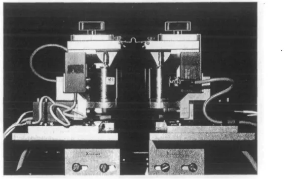
Measuring system
The mesio-distal and transverse forces as well as the moments of rotation delivered by the activated arches were measured with a com-puter-based strain-gauge system (Fig. 5). In the measuring machine, the two ends of the arch
"' i 10 r L.U *
1
J
• • -7 ', j !Figure 4 Check of degree of activation with one end of the palatal arch fastened in a vice.
eliminate the transverse contractive force resulting from the derotation.
Measuring procedure First series
In this series, the degree of activation was checked with the scale of degrees to have the same magnitude on both sides (symmetrical activation). When necessary, adjustments were made until the activation was the same on both sides. The check was made with the clutches unlocked. These were thereafter locked in the starting (vertical) position.
Second series
After activation, the arch was inserted in the measuring machine and the measurements were made in the starting position and during de-activation. Thus, for the second series of arches no check was made in the machine for similarity of activation on the two sides because this would not have been possible in clinical use. Results
If the moments on both sides are the same, the mesio-distal force will be zero. If this is not the case, the force on one side will be in the mesial and that on the other side in the distal direction, and of equal size. As the direction of the mesio-distal force is of no importance in this study, the tables give the absolute value of the mesio-distal force as the mean of the values measured at the two ends of the arch wire. The transverse force may be expansive or contractive. The tables give the mean of the values measured at the two ends of the arch whereby a contractive force is designated with a minus sign. The moments on the two sides are in the opposite
Figure S Measuring machine used to record the moments and forces delivered by the transpalatal arches.
Figure 6 Scales for the determination of the degree of deactivation.
direction and should ideally be of the same magnitude (zero difference).
The results of the measurements of the first series of arches are given in Table 1. The mesio-distal force was, for all three arch sizes, related to the size of the moments and decreased with the decrease of the moment during deactivation (Table 1). In other words, it was more difficult to balance the moments on the two sides when these were large. The median transverse force
was, for all three sizes of the GAC arch, slightly expansive at full activation (10-12 mm) but became increasingly contractive during deac-tivation and was for all three arch sizes of similar magnitude at full deactivation. The con-tractive force could be eliminated by decreasing the distance between the two ends of the arch. This was done as the final step of a meas-uring procedure after full deactivation of the moments.
moments were delivered compared with 10 mm activation of the same arch. With 5 mm activa-tion, useful moments were only produced up to
The forces and moments delivered by the GAC arches of the second series are given in Table 2. This series offered the opportunity to
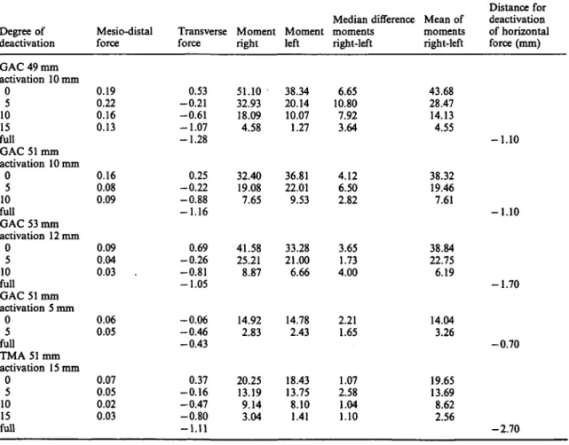
Table 1 Median of mesio-distal and transverse forces (in N) and moments of rotation (in mNm) delivered by five transpalatal arches after controlled symmetrical activation for molar rotation (first series).
Degree of deactivation GAC 49 mm activation 10 mm 0 5 10 15 full GAC 51 mm activation 10 mm 0 5 10 full GAC 53 mm activation 12 mm 0 5 10 full GAC 51 mm activation 5 mm 0 5 full TMA 51 mm activation 15 mm 0 5 10 15 full Mesio-distal force 0.19 0.22 0.16 0.13 0.16 0.08 0.09 0.09 0.04 0.03 . 0.06 0.05 0.07 0.05 0.02 0.03 Transverse force 0.53 - 0 . 2 1 - 0 . 6 1 - 1 . 0 7 - 1 . 2 8 0.25 - 0 . 2 2 - 0 . 8 8 - 1 . 1 6 0.69 - 0 . 2 6 - 0 . 8 1 - 1 . 0 5 - 0 . 0 6 - 0 . 4 6 - 0 . 4 3 0.37 - 0 . 1 6 - 0 . 4 7 - 0 . 8 0 - 1 . 1 1 Moment right 51.10 32.93 18.09 4.58 32.40 19.08 7.65 41.58 25.21 8.87 14.92 2.83 20.25 13.19 9.14 3.04 Moment left 38.34 20.14 10.07 1.27 36.81 22.01 9.53 33.28 21.00 6.66 14.78 2.43 18.43 13.75 8.10 1.41 Median difference moments right-left 6.65 10.80 7.92 3.64 4.12 6.50 2.82 3.65 1.73 4.00 2.21 1.65 1.07 2.58 1.04 1.10 Mean of moments right-left 43.68 28.47 14.13 4.55 38.32 19.46 7.61 38.84 22.75 6.19 14.04 3.26 19.65 13.69 8.62 2.56 Distance for deactivation of horizontal force (mm) - 1 . 1 0 - 1 . 1 0 - 1 . 7 0 - 0 . 7 0 - 2 . 7 0
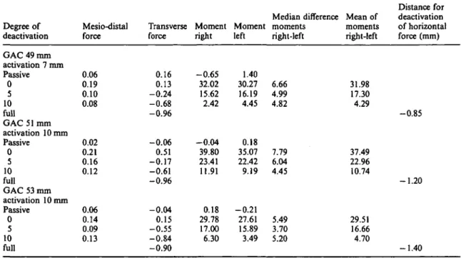
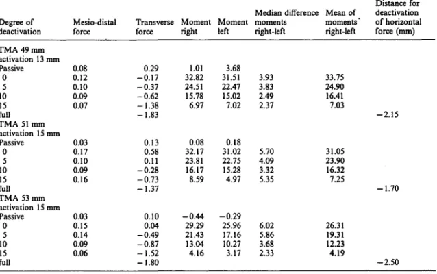
Table 2. Median of mesio-distal and transverse forces (in N) and moments of rotation (in mNm) delivered by 10 transpalatal arches after symmetrical activation for molar rotation (second series).
Median difference Mean of Degree of Mesio-distal Transverse Moment Moment moments moments deactivation force force right left right-left right-left
Distance for deactivation of horizontal force (mm) GAC 49 mm activation 7 mm Passive 0 5 10 full GAC 51 mm activation 10 mm Passive 0 5 10 full GAC 53 mm activation 10 mm Passive 0 5 10 full 0.06 0.19 0.10 0.08 0.02 0.21 0.16 0.12 0.06 0.14 0.09 0.13 0.16 0.13 0.24 0.68 0.96 0.06 0.51 0.17 0.61 0.96 0.04 0.15 0.55 0.84 0.90 - 0 . 6 5 32.02 15.62 2.42 - 0 . 0 4 39.80 23.41 11.91 0.18 29.78 17.00 6.30 1.40 30.27 16.19 4.45 0.18 35.07 22.42 9.19 - 0 . 2 1 27.61 15.89 3.49 6.66 4.99 4.82 7.79 6.04 4.45 5.49 3.70 5.20 31.98 17.30 4.29 37.49 22.96 10.74 29.51 16.66 4.70 - 0 . 8 5 -1.20 -1.40
GAC = GAC prefabricated stainless steel transpalatal arch.
check the forces and moments when the arches were judged by the examiner to be passive. The median forces and moments with the 'passive' arches were, small. This was also the case for the maximum forces measured with individual arches (Table 4). The maximum moments of individual 'passive' arches were, however, rela-tively large (8.28 mNm for the 49 mm arch and 6.95 mNm for the 53 mm arch, Table 4).
The median mesio-distal forces exerted by the activated arches were relatively small and tended, like those of the first series, to decrease during deactivation (Table 2). Individual mesio-distal forces could, however, be relatively large (0.57 N with the 51 mm arch, Table 4). At full activation (0 degrees of deactivation) all sizes of arches showed small median expansive forces but for individual arches the transverse force varied between expansive and contractive (Table 4). At full deactivation, however, all arches of all three sizes delivered contractive forces which were of the same median size. The mode of activation of the GAC arches of the second series resulted, for all three arch sizes, in fairly similar median moments which rapidly decreased during deactivation.
The TMA arches of the second series also delivered small median forces when judged to be passive but with a variation up to 0.54 N mesio-distal and 1.36 N expansive force (Tables 3 and 4). The median 'passive' moments from the 49 mm TMA arch were greater than those from the 'passive' GAC arch of the same size. Individual TMA arches could show large moments when believed to be passive, with an extreme value of 22.59 mNm for one 49 mm arch. The second largest 'passive' moment for a TMA arch was 7.43 mNm.
The mesio-distal forces exerted by the activ-ated TMA arches were small, with a maximum value of 0.39 N, and generally decreased during deactivation. The transverse forces at full activa-tion were varying (expansive or contractive). At full deactivation, however, all arches delivered a contractive force. During deactivation the transverse forces were generally of the same magnitude as those of the GAC arches. At full deactivation, however, the median contractive forces of the 49 mm and of the 53 mm arches were double those of the GAC arches.
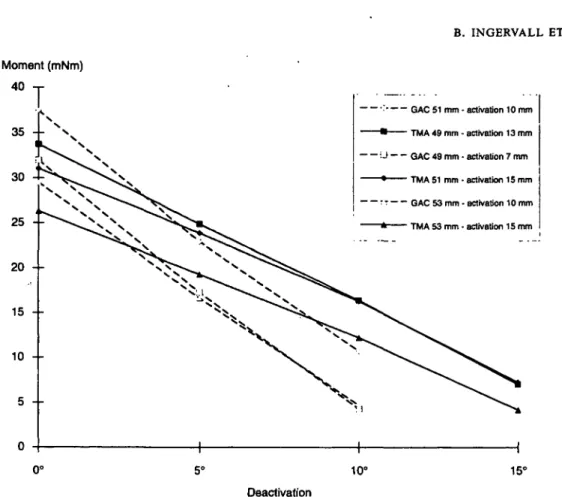
The moments delivered by the TMA arches at full activation were of the same magnitude
activation 15 mm Passive 0 5 10 15 full TMA 53 mm activation 15 mm Passive 0 5 10 15 full 0.03 0.17 0.10 0.09 0.16 0.03 0.15 0.14 0.09 0.06 0.13 0.58 0.11 - 0 . 2 8 - 0 . 7 3 - 1 . 3 7 0.10 0.04 - 0 . 4 9 - 0 . 8 7 - 1 . 5 2 - 1 . 8 0 0.08 32.17 23.81 16.17 8.59 - 0 . 4 4 29.29 21.43 13.04 4.16 0.18 31.02 22.75 15.28 4.97 - 0 . 2 9 25.96 17.16 10.27 3.17 5.70 4.09 3.32 5.35 6.02 5.86 3.68 2.33 31.05 23.90 16.32 7.25 26.31 19.31 12.23 4.19 - 1 . 7 0 - 2 . 5 0 TMA = (5-titanium transpalatal arch.
Table 4 Maximum values of mesio-distal and minimum and maximum values of transverse forces (in N) and of moments (in mNm) delivered by 10 'passive' transpalatal arches and after symmetrical activation for molar rotation (second series).
Arch and activation GAC 49 mm passive activation 7 mm GAC 51 mm passive activation 10 mm GAC 53 mm passive activation 10 mm TMA 49 mm passive activation 13 mm TMA 51 mm passive activation 15 mm TMA 53 mm passive activation 15 mm Mesio-distal force max 0.13 0.53 0.06 0.57 0.19 0.31 0.54 0.39 0.22 0.29 0.08 0.25 - 0 . 1 1 - 1 . 5 1 - 0 . 3 6 - 0 . 5 2 - 0 . 2 7 - 0 . 8 8 - 0 . 1 6 - 0 . 3 8 - 0 . 4 0 - 0 . 4 9 - 0 . 2 3 - 0 . 7 2 Transverse min 0.45 1.41 0.08 1.15 0.18 0.63 1.36 1.35 0.38 0.89 0.41 0.64 force max - 1 . 6 8 23.16 - 0 . 5 4 29.91 - 1 . 1 3 23.04 - 1 . 4 7 29.91 - 3 . 1 3 23.66 - 2 . 9 3 20.04 Moment min 3.32 43.04 0.42 47.76 6.95 32.98 4.43 40.48 6.05 42.12 0.82 31.95 right max - 0 . 7 5 23.02 - 0 . 3 8 24.60 - 3 . 3 1 25.91 - 0 . 4 2 27.40 1.69 23.52 - 2 . 1 2 21.56 Moment left min max 8.28 40.53 1.63 52.05 2.55 39.92 22.59 38.69 6.18 37.79 1.90 31.97
as those from the GAC arches but they decreased considerably more slowly during deactivation (Fig. 7). Thus, useful moments were still delivered by the TMA arches at 15 degrees of deactivation.
Discussion
In spite of the precautions taken in the first series of arches to achieve the same degree of activation at the two ends of the arch, different
Moment (mNm) 40 - r -•'. GAC 51 mm - activation 10 mm ""• TMA 49 mm - activation 13 mm - '•• J GAC 49 mm - activation 7 mm • TMA 51 mm - activation 15 mm - r T GAC 53 mm - activation 10 mm - TMA 53 mm - activation 15 mm 10° 15° Deactivation
Figure 7 Moments delivered by GAC prefabricated stainless steel (GAC) and (3-titanium (TMA) arches of the second series at varying degrees of deactivation.
moments were always obtained. The degree of activation was checked in the measuring machine and adjusted until the same on both sides. In most cases, many adjustments were necessary. This is probably one of the reasons for the dissimilarity of moments measured.
The frequent adjustments had work-hardened the wire to a different degree on the two sides and thereby changed the limit of elasticity. This effect was most marked in the steel arches and at higher degrees of activation.
The activation of the second series of arches was undertaken in a way simulating clinical use. It was encouraging to note that it was possible to adjust the arches to a passive state with only small forces and moments remaining when the arches were believed to be passive. The smallest 'passive' forces were generally obtained with the steel arches while some TMA arches could exert relatively large forces and moments when believed to be passive. Our results agree with those of Jager et al. (1992), who were unable
to eliminate all forces and moments from trans-palatal arches when adjusting for passivity. In contrast to our findings, however, they recorded smaller residual forces and moments with TMA than with steel arches.
It was also encouraging that the differences between the moments and the variation between the arches (not shown in the tables) were not larger in the second than in the first series of arches. This means that a reasonable consist-ency of forces and moments is obtainable in clinical use. The use of a vice was found to be of great help in the activation of the arches since the arch can be held securely in the vice during activation, which can also be checked in a satisfactory way. The use of a vice in the clinical setting is, therefore, recommended.
The difference of the moments on the two sides resulted in mesio-distal forces which were generally low. In individual cases, however, these forces reached levels capable of moving the molars in a mesio-distal direction. As such
of the tooth-supporting tissues. A way to obtain smaller moments would be less activation of the arches. However, with steel arches this would result in only a small working range. An example is the 51 mm GAC arch activated only 5 mm, which delivered a moment of 14 mNm but only 3 mNm after 5 degrees of deactivation (Table 1). Because of their large working range, TMA arches are much better in this respect. The use of TMA arches is recommended, at least in cases with a large need of derotation. An objection to the use of TMA arches could be breakage during fabrication and activation due to brittleness. We did not find this to be a great problem and although occasional break-age of TMA arches occurred, this also arose with steel arches.
All arches delivered a contractive force of deactivation. The size of the contractive force varied but it was sufficiently large to be clinically relevant. The decrease of the transverse distance necessary to eliminate the contractive force was
References
Andrews L F 1972 The six keys to normal occlusion. American Journal of Orthodontics 62: 296-309
Carlon J A 1973 Die Rotation des ersten Oberkiefermolaren. Informationen aus Orthodontie und Kieferorthopadie 2: 137-162
Jager A, Planert J, Modler H, Gripp L 1992 In-vitro-Studie zur Anwendung von Palatinalbdgen bei der Kontrolle der Position oberer Molaren. Fortschritte der Kieferorthopadie 53: 230-238
Lamons F F, Holmes C W 1961 The problem of the rotated maxillary first permanent molar. American Journal of Orthodontics 40: 259-271
Melsen B, Burstone Ch J 1990 The transpalatal arch and the lower lingual arch. Their use as active and passive appliance. In Melsen B, Burstone Ch, Introduction to biomechanics, Syllabus University of Aarhus
Stoller A E 1954 The normal position of the maxillary first permanent molar. American Journal of Orthodontics 40: 259-271
Ten Hoeve A 1985 Palatal bar and lip bumper in nonextrac-tion treatment. Journal of Clinical Orthodontics 19: 272-291