Design and Assessment of a Super High Speed, Hybrid Hydrofoil/SWATH Crew Boat
By
Vasileios Georgiadis
Bachelor of Science in Mechanical Engineering, Hellenic Naval Academy, 2006
MASSACHUSETTS INSTITUTE
OF TECHNOLOGY
AUG 15 2014
LIBRARIES
SUBMITTED TO THE DEPARTMENT OF MECHANICAL ENGINEERING IN PARTIALFULFILLMENT OF THE REQUIREMENTS FOR THE DEGREES OF
NAVAL ENGINEER AND
MASTER OF SCIENCE IN MECHANICAL ENGINEERING
AT THE
MASSACHUSETTS INSTITUTE OF TECHNOLOGY
JUN[2014
2014 Vasileios Georgiadis. All rights reserved. The author hereby grants to MIT permission to reproduce
and to distribute publicly paper and electronic copies of this thesis document in whole or in part
in any medium now known or hereafter
created-Signature redacted
Signature of Author: S Certified by: Certified by: Accepted by: 0 - ____ .1. . . ~ .~ ~ "" ileli;~~eorgiad is Depirtment of Mechanical Engineering May 9, 2014Chryssostom Chryssostomidis, Director of MIT Sea Grant Dohe Professor of Ocean Science and Engineering Professor, Department of Mechanical Engineering
%% , Thesis Supervisor
Stefano Br olara, Assisfalit Director for Research at MIT Sea Grant esearch Scientist, Department of Mechanical Engineering Thesis Advisor
Signature
redacted--David E. Hardt Chairman, Department Committee on Graduate Studies Ralph E. and Eloise F. Cross Professor of Mechanical Engineering
IgildLU11=
11=
d
SDignaLtr:
re:dacted
Design and Assessment of a Super High Speed, Hybrid hydrofoil/SWATH Crew Boat
By
Vasileios Georgiadis
Submitted to the Department of Mechanical Engineering on May 9, 2014 in Partial Fulfillment of the Requirements for the degrees of Naval Engineer and
Master of Science in Mechanical Engineering
Abstract
This thesis presents the preliminary design and assessment of Wavecutter, an innovative super high speed, hybrid hydrofoil/SWATH crew boat. The intended mission of the vessel is the very-fast transportation of crew and cargo, to and from offshore installations. The design builds on Brizzolara's unmanned high speed hybrid SWATH/hydrofoil vessel concept (Brizzolara, 2010), maintaining the dual operating mode: foilborne to reach top speed of 85 knots in moderate sea states and a displacement SWATH to sail in the higher sea states. This vessel is expanding the family of unmanned hybrid SWATH vessels of Brizzolara and Chryssostomidis to include manned vessels (Brizzolara & Chryssostomidis, 2013). The special hydrofoil profile recently optimized and verified by model tests in free-surface cavitation tunnel, has been adopted, to ensure high lift to drag ratios and avoid typical instability phenomena of conventional super-cavitating hydrofoils (Brizzolara,
2013). The surface piercing configuration of the hydrofoils was adopted in order to
make the vessel inherently stable, without the use of control mechanisms.
The general design phase was focused on the integration of the manned module, internal arrangements, weight estimation, speed profile determination and engine selection. The hydrofoil design phase limits on resizing the four surface-piercing super-cavitating hydrofoils to keep the vessel even keel at maximum speed. To achieve this, the front foils need to have a larger size than the aft ones, due to the trim moment produced by the turbo-jet thrust force. The feasibility assessment phase in foil borne mode confirmed the static stability of the vessel and good seaworthiness in waves. It is recommended that future work be conducted with
CFD simulations in unsteady conditions, to obtain a more accurate understanding of
the vessel's dynamic behavior.
Thesis Supervisor: Chryssostomos Chryssostomidis
Acknowledgements
During my studies at MIT, I have benefited greatly from the Mechanical Engineering Department. The 'mens et manus' culture of the department has given me a new perspective, which I will always carry with me in my life. The course infrastructure and faculty expertise of the program has strengthened my engineering skillset. Therefore, I would like to sincerely thank the staff, the professors and my colleagues for this unique experience. I feel privileged to be a member of the MIT engineering school.
I would like to express my sincere appreciation and respect to my advisor, Professor
Stefano Brizzolara, for his support throughout my thesis. Observing his advanced engineering intuition, a result of years of hard work, inspired me to become a better engineer myself. His amicable character made working under his guidance enjoyable and seamless.
I would like to express my gratitude to Professor Chrys Chryssostomidis for
welcoming me to be part of the greater research community of Sea Grant, and for supervising my thesis research.
I would like to express my gratitude to the Hellenic Navy and the Greek government
in general, for sponsoring my studies in MIT. I aim to use the new skillset gained from MIT to advance the Hellenic Navy's capabilities and do my part in helping
Greece improve, especially after the recent financial crisis.
But most of all, I would like to thank my wife. Had it not been for her emotional and practical everyday support, I would never have had the stamina and time to study hard and complete my MIT degrees.
Table of Contents
Abstract...3
A cknow ledgem ents...4
Table of Contents...5 List of Figures ... 7 List of Tables...8 1 Introduction ... 9 1.1 M otivation/benchm arking... 9 1.2 Requirements ... 10 2 General design ... 12 2.1 Concept design ... 12
2.2 M anned com partm ents design ... 13
2.3 Speed profile, propulsion system configuration and engine selection...15
2.4 W eight estim ation... 22
2.5 General arrangem ents... 24
2.5.1 Three dim ensional view s ... 24
2.5.2 Tw o dim ensional draw ings... 26
2.6 Evacuation plan...33
3 H ydrofoil Design ... 37
3.1 Foil type, configuration and profile selection... 37
3.2 Hydrofoil sizing... 39
3.2.1 Equilibrium and zero trim at m axim um speed... 39
3.2.2 Clearance to avoid slamming and foil folding mechanism limitations... 42
3.2.3 Sizing conclusions ... 43
3.2.4 Consideration of trim at lower foil borne super-cavitating speeds... 44
3.3 Hydrofoil prelim inary strength analysis... 45
3.3.1 Other strength considerations... 46
4 Feasibility assessment...47
4.1 Static stability ... 47
4.2 Dynam ic behavior... ... ,49
4.2.1 M ethods and assum ptions... 49
4.2.2 Equations of m otions... 51
4.2.3 Inertia term s...51
4.2.4 Restoring forces...52
4.2.5 External forces... 54
4.2.6 Sim ulation results ... 58
5 Conclusions and recommendations ... 61
6 Appendix... Error! Bookm ark not defined. 6.1 Operational sea state requirement (R6) derivation ... 64
6.2 Data analysis of m odel experim ents... 65
6.3 Estimation of drag and lift in air ... 71
6.4 Added mass approximations... 72
6.5 Vessel forces at a random heave and pitch position ... 74
6.6 Differential equations solver using numerical methods ... 74
6.6.1 Transformation of differential equations into state space form... 75
6.6.2 Numerical model validation... 76
List of Figures
Figure 1: S. Brizzolara's unmanned ASV HYGE-SWATH ... 12
Figure 2: Wavecutter concept design... 13
Figure 3: Procedural flow chart... 14
Figure 4: Manned compartment placement-profile view ... 15
Figure 5: Displacement mode... 15
Figure 6: Transition phase...16
Figure 7: Foil borne mode...16
Figure 8: Propulsion system...19
Figure 9: Total drag force distribution at maximum speed in equil. condition... 21
Figure 10: Wireframe profile view for weight estimation... 23
Figure 11: 3-D view from forward position with vessel components explained...24
Figure 12: 3-D view from backward position... 24
Figure 13: 3-D compartment inside view... 25
Figure 14: 3-D view of inside of passengers and cargo rooms ... 25
Figure 15: 2-D front view vessel dimensions ... 26
Figure 16: 2-D profile view vessel dimensions... 27
Figure 17: 2-D top view vessel dimensions... 27
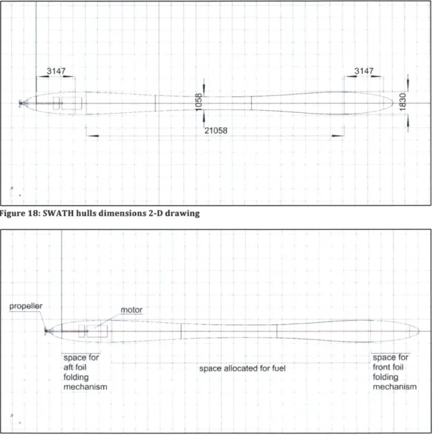
Figure 18: SWATH hulls dimensions 2-D drawing... 28
Figure 19: SWATH hulls space allocation 2-D drawing... 28
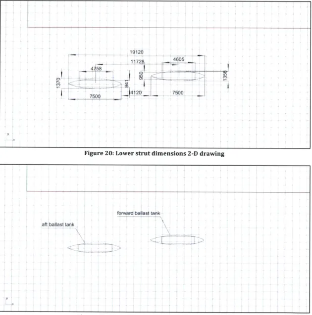
Figure 20: Lower strut dimensions 2-D drawing... 29
Figure 21: Lower strut space allocation 2-D drawing ... 29
Figure 22: Upper strut dimensions 2-D drawing... 30
Figure 23: Upper strut space allocation 2-D drawing... 30
Figure 24: Wing and wing deck dimensions 2-D drawing... 31
Figure 25: Wing and wing deck space allocation 2-D drawing... 31
Figure 26: Manned compartments dimensions 2-D drawing... 32
Figure 27: Manned compartments space allocation 2-D drawing ... 32
Figure 28: Evacuation plan step 1... 34
Figure 29: Evacuation plan step 2... 34
Figure 30: Evacuation plan step 3... 35
Figure 31: Evacuation plan step 4... 35
Figure 32: Evacuation plan step 5... 36
Figure 33: Evacuation plan step 6... 36
Figure 34: Hydrofoil profile-simulation under unsteady turbulent flow... 37
Figure 35: Hydrofoil model used in experiments... 38
Figure 36: Model experiments sample photo... 38
Figure 37: Forces 2-D drawing with reference point and sign convention... 39
Figure 38: Moment distribution at maximum speed in equilibrium condition... 41
Figure 39: Weight distribution at maximum speed in equilibrium condition... 42
Figure 40: Clearance from SWATH hulls at high speeds ... 43
Figure 41: Foil sizing (all distances in m) ... 44
Figure 43: Righting moment graph for small angles... 49
Figure 44: Wave length twice LBF... 54
Figure 45: Wave length equals LBF ... 55
Figure 46: External forces for the two cases of wave length... 57
Figure 47: Dynamic behavior simulation 1-calm sea with initial conditions... 58
Figure 48: Dynamic behavior simulation 2-wave length twice LBF, wave height 0.5 m... 59
Figure 49: Dynamic behavior simulation 3-wave length equals LBF, wave height 0.5 m... 60
Figure 50: Gabrielli-von Karman graph of efficiency... 62
Figure 51: NATO Sea State numeral table... 65
Figure 52: Model experiments measurement graph sample... 67
Figure 53: Foil drag force coefficient plot based on experimental data ... 68
Figure 54: Foil side force coefficient plot based on experimental data... 69
Figure 55: Foil lift force coefficient plot based on experimental data... 69
Figure 56: Wing top view geometry... 72
Figure 57: Part of foil contributing to added mass ... 73
Figure 58: Spacecraft landing on a planet problem... 76
Figure 59: Model solutions for the problem 'Spacecraft landing on a planet'... 78
Figure 60: Known solutions for the problem 'Spacecraft landing on a planet'... 79
List of Tables Table 1: Existing crew transportation vessels...9
Table 2: Design Requirements... 10
Table 3: Derived requirements... 11
Table 4: Vessel speed profile ... 17
Table 5: Diesel engine selection for displacement mode ... 18
Table 6: Selected turbofan characteristics... 21
Table 7: Weight estimation... 22
Table 8: Trims at lower super-cavitating speeds... 45
Table 9: Materials considered for hydrofoils... 46
Table 10: Final design main characteristics... 61
Table 11: Seakeeping analysis results summary ... 63
Table 12: Ocean statistics for Gulf of Mexico... 64
Table 13: Chord Froude number comparison... 66
1 Introduction
The state of the art vessels in fast transportation in speed ranges above 70 knots lack seaworthiness and payload capacity. The motivation for this design is to create a better vessel for rapid crew or small goods transportation from harbors to offshore installations.
1.1 Motivation/benchmarking
The need for rapid transportation of industrial personnel between harbor and offshore installation is currently covered by planing hulls and some hydrofoil vessels. The maximum speed reached by planing hulls is in the range of 40-50 knots in almost flat seas, while speed rapidly falls in the 15-18 knots range already, in moderate sea states. Hydrofoil vessels can reach speeds of around 60 knots. However, they use fully submerged foils, which require complex control mechanisms and lack seaworthiness. These type of hydrofoil vessels switch to displacement mode, when encountering heavy weather. For reaching speeds above
70 knots, one must use helicopters or surface effect ships. These vessels have even
higher limitations than planing hulls and hydrofoil vessels in terms of seaworthiness. In addition they are very limited in payload capacity.
Some representative transportation vehicles that address this need today are presented in Table 1. The most important attributes of these vessels are crew payload, cargo payload, maximum sustainable speed, endurance and price. An example of operation of a helicopter would be to transfer medical personnel to an oil rig due to a medical emergency. An example for use of a monohull fast crew supplier would be the regular monthly route to perform personnel transfer. A SWATH vessel, as an example, could be used to transport personnel to an offshore wind installation for maintenance. A hydrofoil industrial personnel transportation vessel could not be found; a passenger ferry hydrofoil vessel is listed in the table below for reference.
Table 1: Existing crew transportation vessels
Vehicle Industrial Cargo Maximum Endurance Price/per
Personnel Payload Sustainable range passenger
Payload (tons) Speed (nautical
(people) (knots) miles)
Helicopter S- 9 0 155 345 Large
76C++
(Sikorsky)
Monohull Fast 29 Unknown 40 Unknown Small
Crew Supplier 1605 (Damen)
SWATH crew 24 0 23 500 Medium
boat (Danish
Boeing 929-100 243 Unknown 45 Unknown Medium
1.2 Requirements
Table 2 shows the requirements generated from the vessel's intended mission. Requirements R1, R2 and R3 are based on the rational that Wavecutter should have at least the same capability in these areas as some existing vehicles. Wavecutter is intended to be operated in the higher speed ranges, being a hydrofoil vessel, hence the requirement R4. Requirement R5, endurance, is generated based on the distance of the furthest oil rig from the Gulf of Mexico central harbor, with +50% allowance for future growth in the deep water oil drilling segment of the industry. Requirement R6 is based on sea statistics for the Gulf of Mexico, so that the vessel will be able to operate safely approximately 85% of the time (more information is
given in the Appendix, section 6.1).
Table 2: Design Requirements
Requirement ID Requirement Goal Threshold
R1 Passengers 24 20 R2 Cargo (tons) 15 10 R3 Crew 4 6 R4 Maximum speed 85 70 R5 Endurance (n. 600 400 miles) R6 Operational Sea 4 3 State
Table 3 presents derived requirements. Derived requirements are requirements generated as a consequence of design requirements, whether directly stated in Table 2 or inferred. D1 is derived from the fact that manned compartments are expected to accommodate people and is based on the average male height of 1.8 m.
D2 is a requirement derived from R6, the operational sea state requirement. D3 is
decided to account for the needed space for structural support. By assigning this extra space, the present study allows future studies to conduct global structural design of the vessel. Requirement D4 is a consequence of requirements R2, using the density of water (1000 kg/ cu. m.) to calculate the required volume, with an allowance of +50% volume. D8 and D9 are derived from R6, but the vessel is expected to switch to displacement mode when encountering a sea state of 3 and higher.
Table 3: Derived requirements
Requirement Derived requirements Goal Threshold
ID
D1 Minimum 2.2 2.0
manned compartment height [m]
D2 Minimum distance of lowest 2.5 2
point of wing/deck from sea level [m]
D3 Allowance for structural support 0.5 all 0.35 above
of manned compartments [m] around compartment, 0.5 below and 0.5 on the sides
D4 Storage space for cargo [M3] 22.5 15
D8 Displacement mode operational 4 3
sea state
D9 Foil borne mode operational sea 3 2
2 General design
The general design of the vessel is presented in this section. The general design phase starts from the concept design and continues with the integration of the manned module, internal arrangements, weight estimation, speed profile determination and engine selection. At the end of the section a preliminary evacuation plan is demonstrated.
2.1 Concept design
The concept design of the vessel is based on S. Brizzolara's autonomous unmanned hybrid concept design (Brizzolara, 2010, p. 10), shown in Figure 1. The design features a hybrid 20 m long vessel, capable of reaching a maximum speed of 120 knots, intended to carry a payload of 5 MT. The unmanned vessel sails in displacement mode at low speeds, the hydrofoils being kept in vertical position in this mode, as shown on the top right of the figure. Above take-off speed, the vessel switches to foilborne mode, shown in the bottom right of the figure. In foilborne mode, lift is partially provided by the wing shaped deck. Volume is allocated to carry the payload in the front part of the wing, noticed in the left part of the figure.
COVUAsOC#4ZNT moot
PATENT PENDING
Figure 1: S. Brizzolara's unmanned ASV HYGE-SWATH
The required payload of Wavecutter is significantly different both in weight, weight distribution and type. The very fact that the vessel is intended to be manned generates extra requirements and considerations. Safety is of great concern, which is why a whole section is devoted to an evacuation plan (2.6). The risk of capsizing is also of major concern, which is why stability is the first on the list of feasibility assessments. In addition, seakeeping and dynamic behavior are topics that require more attention than they would in an unmanned vessel, which is the second priority of the feasibility assessment phase of this study.
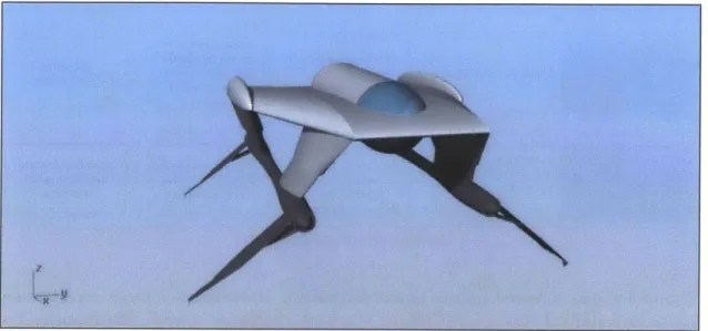
Figure 2 presents the preferred concept design of Wavecutter. The cylindrical shaped nacelle placed in the middle of the wing deck contains all manned compartments. At this stage of the design, neither the exact size of the compartments or their configuration had been decided upon. The molded diameter of the nacelle represented in Figure 2 is about 5 m. An alternative concept design option is to increase the thickness of the wing deck to 3 m, to be able to incorporate compartments directly inside the wing. This concept was discarded, because it increases the wing's weight significantly, and it would be unlikely that the wing will provide any lift at all with this shape. Other options were also considered, but only the preferred one is shown here.
4,LIN,
Figure 2: Wavecutter concept design
2.2 Manned compartments design
The basic intended function of this vessel is to transport people, thus the manned compartments were designed in advance. To better understand the problem, this procedure has been mapped in a flowchart, shown in Figure 3. Mapping out the
procedure helps infer the vessel's required attributes. The main difficulty in
compartment design and general arrangements is the limited available space in this vessel. Unlike conventional vessels, the only spaces here are inside the wing, struts and SWATH hulls. Thus, in this design stage, effort was made to consume minimum space from the available. Another challenge has been the peculiar sensitivity of vessel trim to weight distribution, unlike for a conventional displacement hull. Manned compartments need to be a continuous space in the vessel. The only part of the vessel that can facilitate this is the wing. This continuous space needs to be shaped to reduce aerodynamic resistance. This study did not focus in optimizing this shape for aerodynamic resistance; a shape similar to an airplane's fuselage was adopted. This continuous space needs to include room for passengers, crew and
cargo. The direct and indirect system requirements derived from the intended procedure are shown in Figure 3.
Crew organizes Crew enforces Crew controls vessel Crew controls and boarding and .MM safety regulations mw speed, heading and wo organizes vessel
prepares for and starts engines maneuvers berthing departure
Passengers enter Passengers are Passengers are Passengers exit
vessel seated transported safely vessel
Sturdy seats with
Passenger seats, appropriate safety Berthing Entry door or hatch crew seats, control belts, appropriate mechanism
panels heading control mechanism
Life rafts, life vests,
Emergen door or W.C., crew space, Stability, structural Crew controls and
. emergency integrity, safe sea- organizes vessel prim entry is berthing, fire keeping motions berthing
fiahtine eauipment
Figure 3: Procedural flow chart
Figure 4 shows manned compartment placement. Normally, in a large naval vessel there is a control room, from where the crew members control and monitor the vessel's systems. There is also a need for a navigation room, from where a visual appreciation of the surroundings will be possible. To keep consumed space low, these two rooms were combined into a common control room, which was placed in the front part of the wing. From the procedural flow chart, there is also a need for crew office space, W.C. and an emergency berthing room. All these spaces are allocated in a common compartment behind the control room compartment. The emergency berthing room will be used in case someone on board, crew member or passenger, has a sudden medical need to rest. This could also serve as a resting place for the crew member who will perform watch duty while berthed at harbor. The passenger space and control room dimensions were calculated based on the average human standing and sitting 'box' dimensions, with some allowance. These calculations were trivial and are not presented here. It is noticed that there are two hatches in the compartment placement profile drawing. The aft hatch is for normal entry/exit and the forward hatch is intended for emergency entry/exit. The forward hatch includes a portable 'fire-escape' type ladder, not shown in the drawing. The entry space's dimensions have been estimated based on the required cargo capacity of the vessel. The dimensions of the tube which contains the manned compartments has been estimated based on the structural allowance requirement
(D3). The exact dimensions of the manned compartments and the size of their
internal components are presented in section 2.5.
2.3 Speed profile, propulsion system configuration and engine selection
Adopting the parent vessel's operational profile, Wavecutter operates in two modes, displacement and foilborne. In displacement mode, hydrofoils are folded and buoyancy is provided by the submerged SWATH hulls. In the transition phase, hydrofoils are rotated to be perpendicular to the water level, providing maximum lift for the given speed. As the vessel lifts, hydrofoils rotate further, until they reach a negative dihedral angle of -1400, or a 400 angle from the water level directly above the foils. The two modes along with the transition phase are shown in the three figures below.
Figure 6: Transition phase
Figure 7: Foil borne mode
The submerged area of the hydrofoils decreases, as speed increases; thus in higher speeds vessel draft is less. The desired speed profile of the vessel before engine selection is shown in Table 4. During engine selection, a change was made in the speed profile, shown in red in the fifth row of Table 4. This change was made due to the limited available space inside the struts: engines with enough power to reach speeds above 17 knots were too large to fit in the available space. However, if a manufacturer is found to make engines of such power small enough to fit in this space, the diesel engines will be able to reach the speed of 27 knots.
Table 4: Vessel speed profile
Mode Speed range [knots] Speed range [m/s]
Displacement 0 17 0.00 8.75
Transitional 17 37 8.75 19.03
Foil borne 37 85 19.03 43.73
Generatrs 0 27 (17) 0.00 13.89 (8.75)
Turbo fans 17 85 8.75 43.73
To select a diesel engine, the resistance has been estimated in displacement mode
for the speed 17 knots. The resistance in displacement has been found with two approaches. In the first approach, the total resistance is decomposed into the resistance of the SWATH hulls, the struts and the wing's.
Rt = RhuIIs + Rstruts + Rwing
Using the ITTC practical guidelines for estimating resistance (F.Campana, 2011), the hulls' and struts' individual resistance is:
Re = Length * Speed kinematic viscosity 0.075 Cf = (log10(Re) - 2)2 Cd = Cf * (1 1.5 Dmax 1 5 . Dmax 3\ +L51 +7 LI
The above is an empirical formula from S. Brizzolara's work (Brizzolara, 2010). 1
R= 1*p*S*Cd *Speed'
Using Oswald's coefficient for wing efficiency (Raymer, 2012, p. 456), the wing resistance is: (CL)z CD = CDO + ( ir * e * AR 1 R =*p * S * (Ci+Cdo) * Speed2 2
However, in the above calculations of total resistance, wave resistance is not taken into account. Wave resistance is important for this vessel, because the volumetric Froude number is greater than 1. Specifically the volumetric Froude number is:
Fn, = Vsip = 1.127
V~shi= 17 knots
V= 245.52 m3, total diplaced volume
To include wave resistance, an alternative approach is followed, to find the total resistance. This approach is based on S. Brizzolara's total resistance comparison of SWATH hulls with different slenderness ratios and Froude numbers (Brizzolara & Villa, 2010, p. 13).
The total resistance with this approach is:
1 2
R= CTv* *P*V ship2 * V= 123 KN
CTv = 0.08, total resistance volumetric coefficient
Diesel engine selection is based on the total resistance calculations from the second approach.
EHP[KW] = Resistance [KN] * Speed
["I
Using typical propulsive, mechanical and electrical efficiency coefficients, the Break Horsepower has been calculated. Break Horsepower divided by 2 gives the required power per engine, and the diesel engine selection is based on this number. The selected engine selected is MTU DQCA (Cummings) rated at 850 KW. These
Table 5: Diesel engine selection for displacement mode
Calculation of needed power of Diesel Generator
EHP [KW] 1076 Maximum speed 8.75
with Diesel [m/s] SHP [KW] 1435 Propulsive 0.75 coefficient (P.C.) BHP [KW] 1511 Mechanical0.95 Efficiency Required power
of Diesel Engines 1679 Electrical efficiency 0.9
[KW] Number of 2 Engines Required power 840 per engine
{KW]
Type of Engine Engine selected 850 selected: DQCA ofpower [KW] Cummings (MTU
engine) I _I
In displacement mode, power is transmitted from the diesel engines to the propeller via electricity. Figure 8 shows the propulsion components. The yellow boxes inside the struts represent the diesel engines, and the smaller green boxes the generators. Power is transmitted through cables to the motors in the aft part of the SWATH hulls, colored red, and finally to the propellers.
Genao"s
- convert diesel's mechanical energy to electric
Diugel ngngg:
- Propulsion in displacements mode (0-18 knots) - Provide electric power in both
modes
- Selected engine type DQCA of
Cummings (MTU)
- Selected rating S50 KW
El. Motors: -Tal
- Variable frequency drn - h
- Transfer energy to propellers - En
1 L-through shaft an
Auddr/LbWiW
- Acts as rudder/stabilizers in foil borne mode, just
like airplane designs
Turbo fan :
- Provide thrust for vessel at foil borne mode (18-85 knots)
- Selected engine type Rolls Royce Trent 560
- Selected rating 267 KN
Ballast tanks:
- Space has been allocated in the lower struts for ballasts tanks - Used for trim control
Fbid-p1tch Propelez:
- Propel vessel in displacement mode
The engines providing propulsion in foil borne mode are turbofan aircraft engines, located right and left of the manned nacelle on top of the wing. These types of engines are rated in KN. In the initial design loop, the turbofan selection has been based on estimations of water and air drag at maximum speed. In the second design loop (this study accomplished two design loops), these calculations are done with greater detail, relying on experimental data for the calculation of water drag, which is the largest of the two components (air and water drag). The selected engine from the first design loop will not be mentioned here, since the second design loop is more accurate in predicting total drag.
In the initial design loop, drag in water has been calculated using the simple assumption of drag being one fifth of lift for hydrofoils. Lifts for front and aft foils have been found from equilibrium conditions at maximum speed, similar to the process followed in section 3.2.1. The resistance of the foil has been found 443.3
KN. The resistance in air was only a small portion of the resistance in water, 5.1%.
The total resistance in the first design loop has been found 466 KN. The resistance in air was:
Rair = Afrontal * CDO * * * Speed 2
In the second design loop, water drag resistance at maximum speed is based on the experimental formulas found in the Appendix in section 6.2.1, instead of assuming a fixed ratio between lift and drag for the hydrofoils. Aid drag is calculated from experimental formulas derived from Hoerner for small aspect ratio wings (Hoerner,
1992). A more detailed explanation of the method for calculating air drag at
maximum speed is found in the Appendix section 6.3.
The distribution of drag components at maximum speed can be seen in Figure 9. Just as in the first design loop, air drag is a small portion of the total drag. The total drag is 483.43 KN. Adding a non-calm sea allowance of +10%, the total drag is
Figure 9: Total drag force distribution at maximum speed in equilibrium condition
The engine database for turbofan selection was the Trent series of Rolls-Royce, because it was the most open source database found. The engine selected is Trent
560, currently used in airplanes Airbus 340-600. The ratings and characteristics of
the engine are shown in Table 6.
Table 6: Selected turbofan characteristics
Engine Trent 560
Entry Into Service 2002 Applications Airbus A340-600 Static Thrust [KN] 266.89
Basic Engine Weight [kg] 4717.36
Thrust to Weight Ratio 5.76
Length [m] 3.91
Fan Diameter [m] 2.47
A recognized technical risk of this design is the placement or airplane turbo fans
close to the sea water surface level. Corrosion problems that may arise due to the salt deposits on the blades may be significant. While technologies do exist that
filtrate most of the sea water from the spray intake, this issue requires further attention in future studies.
2.4 Weight estimation
The weight estimation of the second design loop is shown in Table 7. The initial design loop resulted in a large displacement and draft. If the weight distribution of the first design loop had been adopted, the water level would reach as high the middle part of the upper strut, leaving very little clearance between the water and the wing. The main driver for the large displacement of the vessel in the first design loop was fuel, corresponding to the higher range of the endurance requirement (600
NM).
In the second design loop, the endurance capability was decided 480 NM, as this value is the best compromise of fuel/displacement while maintaining the maximum speed. This results in a decrease in displacement and draft that allows sufficient clearance from the water level to the lower part of the wing. This modification also frees space in the struts that was previously allocated to fuel. Apart from fuel, the foils are also a large component of the weight, This is due to the foil's chosen material, determined from the hydrofoil preliminary strength assessment (3.3). In foil borne speed, the largest loads are imposed upon the hydrofoils and their mechanisms. This is the reason why structural analysis in this preliminary study focuses on the hydrofoils.
Table 7: Weight estimation
Longitudinal position Xg Vertical position Zg
Weight component Weight [t] [m] [m]
Hull 7.74 14.72 0.00 Struts 12.77 17.43 3.73 Wing 22.31 18.12 6.53 Permanent Payload 3.00 19.37 6.21 Fore Foils 30.58 27.20 -2.40 Aft Foils 30.58 2.63 -2.40 El.motor+shafts+props 1.20 0.00 0.00
rotating/folding mech. Fore 0.90 27.14 -0.20
rotating/folding mech. Aft 0.90 2.56 -0.20
Batt+inv. 1.00 11.00 4.00
Electr, Aut & Nav Equipm. 1.00 18.12 6.53
Cables + pipes 1.00 19.37 6.21 2 x Turbofans 9.43 14.15 8.14 2 x Diesels + Generators 13.00 8.24 4.45 Allowance 6.77 17.94 1.91 LIGHT SHIP 142.17 15.11 1.61 Mission Payload 17.24 19.37 6.21 Fuel in Hulls 86.11 14.72 0.00 Fuel in Struts 0.00 0.00 0.00 Service Tank 1.00 8.24 4.95 Ballast Tanks 8.00 16.79 1.70
WEIGHT at FULL LOAD 254.52 15.79 1.44
To appreciate the components and their location in the vessel visually, a ghosted profile view is provided in Figure 10. The scale used is 1 m-1 square.
2.5 General arrangements
This section presents the general arrangements of the vessel, with three dimensional outer deck views, profile compartmentation views and two dimensional internal arrangement views.
2.5.1 Three dimensional views
Figures 11 and 12 show the vessel from a forward and backward viewing perspective respectively, in foil borne mode. The normal and emergency hatches can be seen in green and red on the top of the manned nacelle. The control room can be seen through the transparent viewing window in the front of the nacelle. The hydrofoils are partially submerged; the waterline level corresponds to maximum speed. The rudder serves to maneuver and stabilize the vessel in foil born mode.
Figure 11: 3-D view from forward position with vessel components explained
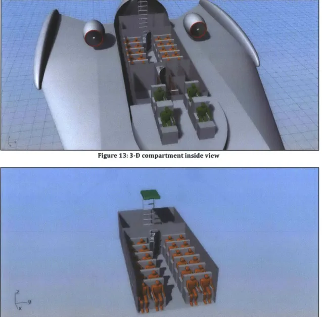
Figure 13 shows a view of the inside of the manned compartments from a forward perspective. Two ladders are seen in this figure. The aft ladder is for normal access to the vessel and the forward ladder is for control room access by the crew. Figure 14 gives a closer view of the passenger room. The seats should accommodate a strong foundation and professional seat belts for vibration and shock absorption.
Figure 13: 3-D compartment inside view
2.5.2 Two dimensional drawings
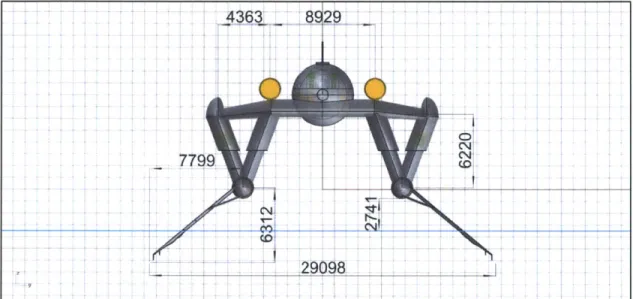
The following three figures are two dimensional drawings, each from a different perspective, and show the vessel's primary dimensions. The waterline level corresponds to the vessel's draft at maximum speed. Important vessel dimensions are seen, such as length overall, length between foils, nacelle size, wing dimensions and others. The longitudinal length between foils plays a major role in the vessel's longitudinal stability and dynamic behavior in waves, because it affects the mass moment of inertia. The nacelle surrounding the manned compartments was sized based on the structural allowance requirement (D3). The nacelle has more volume than required by D3, because it is cylindrically shaped to have a more aerodynamic shape. This extra space will be useful for allocating space for components that could not be predicted in this concept design study, whether that be structural support or other.
4363C
7799
T 29006
14190 4379
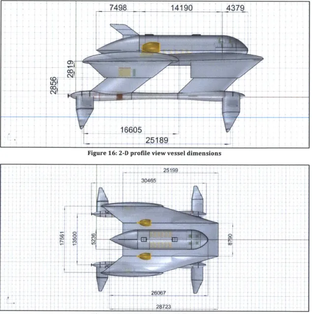
Figure 16: 2-D profile view vessel dimensions
28723
Figure 17: 2-D top view vessel dimensions (0I 00)
H
25189 1~, ~ 7498&Most of the SWATH hulls' space is allocated to fuel, which is due to the endurance requirement (R5). In the forward and aft part of the SWATH hulls some space is allocated to the foil folding mechanisms. A small amount of space is left empty in the forward part of the hulls. In the aft part of the hulls, space is also allocated to the generator, shaft and bearing.
3147
-wL I
21058
3147
_ __
IFigure 18: SWATH hulls dimensions 2-D drawing
propellermor
spac frspace for
front foil folding
mechanism space allocated for fuel
space forf
aft foil folding
mechanism
Figure 19: SWATH hulls space allocation 2-D drawing
Cn
motor
-- --
Ballast tanks are a necessity, especially for this type of vessel, for which trim is
highly sensitive to weight distribution. For example, trim changes from the full load
to minimum operating conditions. Between different operating conditions, ballast tanks will be used to restore trim, by restoring the weight distribution. Most of the space in the lower struts is allocated as ballast.
19120
11728 4605
4 58
4120 7500,
Figure 20: Lower strut dimensions 2-D drawing
Figure 21: Lower strut space allocation 2-D drawing 0'
C.,
forward ballast tank aft ballast tank
Space is allocated in the aft upper struts to include a small high speed diesel engine with its accompanying generator. The front struts include space for electronics. This study did not focus on selecting particular electronics, but several electronics are a necessity for sea going vessels. Gyroscopic electronics, electricity converters, radar processing units are three examples of such necessary electronics.
8257
335 2848
214
8257
2719
Figure 22: Upper strut dimensions 2-D drawing
Figure 23: Upper strut space allocation 2-D drawing
2466 T0 -I 0o
'A
space allocated for electronics
The two figures below present the dimensions and space allocation for the wing and the wing deck.
z5ipa 1S353 I I IZ4~44 jN -~ Tt--~ cv) 0 15460 - $-0 7 - _ 60OO-4000- +
-5569-Figure 24: Wing and wing deck dimensions 2-D drawing
entry/cargo room passen WC.
maned ccmpartment capsu --
-Irr
med berthnon contrl reo
Figure 2S: Wing and wing deck space allocation 2-D drawing
cc; ~
1"'D~l
Lb
Manned compartment dimensions are presented in Figure 26. This figure shows the exact horizontal dimensions of seats and corridors, which were designed to be comfortable but frugal in space consumption. The hatches have been given some margin, because small cargo should be able to fit through them. Enough longitudinal distance is given between seats, to allow space for the human's feet. It can be seen that compartment configuration in this vessel reminds compartmentations in passengers airplanes. In fact, such compartmentations were used as an inspiration source in the concept design phase.
Figure 26: Manned compartments dimensions 2-D drawing
cargo space corridors passenrgers seating IN C crew office control
Figure 27: Manned compartments space allocation 2-D drawing
99 2400 2000 30-.0 1460
I7Th
0 7 :l71 ---- FCO iiII
_7V ;-z2.6 Evacuation plan
This sections describes a preliminary evacuation plan, in case of emergency. This evacuation plan is not inclusive of all the potential dangerous situations that may arise; it is a first approach on safety in case of emergency. The evacuation is shown in a series of steps throughout.
When an emergency situation occurs, it will find the crew and passengers in their normal positions, as showed in Figure 28. Two crew members will continue to navigate and monitor the vessel's machinery from the control room. One crew members will proceed to the passenger cabin and remain there to monitor passengers' safety. The remaining crew member will assess the situation and report any damage to the crew members that are navigating the vessel. After the situation is assessed, appropriate announcements will be made. In the announcements, it will be made clear which exit should be used for proceeding in the wing deck. The crew member that is assessing the situation should have first checked the condition of the emergency exit. If the emergency exit is blocked, the crew member should have checked the normal exit, located in the entry/cargo space. In this demonstration, exit from the emergency hatch has been assumed. It is a given that appropriate SOS signals will be transmitted immediately, when an emergency event occurs.
Passengers will be escorted in the wing deck. One crew member will remain in the passenger cabin, ensuring that passengers are exiting safely. Another crew members will remain on the deck ensuring that the passengers are arriving safely there. During this time the navigating crew members will prepare the vessel for evacuation, shutting down the propulsion system etc.
Navigating crew members will proceed to the deck and a fast count will be conducted, to ensure every passenger and crew member is on deck. Life rafts and escape ladders will be available in the front part of the wing deck, underneath the forward part of the control room. They would be activated remotely from the control room, before the last crew members proceed to the deck, or manually from the deck. The final step will be to board the life rafts and abandon the vessel. All the aforementioned steps are illustrated in Figures 28-33.
. . Crew member
Emergency situations occurs Passenger
Figure 28: Evacuation plan step 1
Crew member
Monitor passengers, check emergency exit Passenger
Escort passengers to the wing deck reamember
Figure 30: Evacuation plan step 3
Count passengers and crew Pasmenber
Proceed to forward deck, release escape crew member
ladders and life rafts S Passenger
Figure 32: Evacuation plan step 5
Proceed to life rafts, abandon vessel Pasmember
3 Hydrofoil Design
The general design of the vessel is followed by the hydrofoil design, presented in this section. Foil type, profile and positioning are adopted from Brizzolara' s design (Brizzolara, 2010). Model experimental measurements are used to predict hydrofoil forces. Equilibrium condition at maximum speed reveals that the front foils need to be larger than the aft (see section 3.2.3 for exact dimensions), to counteract the 'bow-down' tendency of this vessel. This tendency is due to the high position of the turbo fans.
3.1 Foil type, configuration and profile selection
Surface piercing hydrofoils with negative dihedral angle were selected because they provide an inherent stability to the vessel, not requiring the use of control mechanisms, which is desired in this design. These features are adopted from the original design that the vessel is based upon (Brizzolara, 2010, pp. 43-57), as is the configuration of the foils. Thus, this vessel features four surface piercing, super-cavitating hydrofoils with a negative dihedral angle, positioned as shown in section 2.5.
The hydrofoil profile is adopted from S. Brizzolara's (Brizzolara, 2013). This particular version manages to retain steady ventilation under unsteady flow conditions. This can be seen in Figure 34, where the 2D section of the hydrofoil has been simulated in unsteady turbulent flow conditions. The blue area represents the ventilated part and the red area represents the non ventilated part of the fluid. The wedge on the lower surface of the foil serves to trigger cavitation on the back part, allowing the forward part to remain non cavitated. It is this exact capability of the hydrofoil that provides a solid basis for lift and drag prediction under unsteady conditions.
Figure 34: Hydrofoil profile-simulation under unsteady turbulent flow
Foil forces calculations are based on model experimental measurements, provided
by Hochbaum & Eckl (Hochbaum & Eckl, 2012). The model has geometric similitude
to the vessel's tapered part of the hydrofoils (model to actual foil ratio=1:9). The experimental foil is shown in Figure 35. It is a tapered and slightly swept profile (Hoerner & Borst, 1975, pp. 15-1). The lift-to-drag ratio achieved with this design
around super-cavitating speed is approximately 5-to-1. The model hydrofoil can be seen mounted in the cavitation tunnel in the figure below (right photo). Figure 36 shows a photo capture during the experiments. In this figure, the fully ventilated side is seen, which is the upper surface of the 2D foil of Figure 34.
Figure 35: Hydrofoil model used in experiments
3.2 Hydrofoil sizing
The criteria for determining foil sizing were:
e Equilibrium and zero trim at maximum speed
* Sufficient clearance from SWATH hulls to avoid frequent slamming e Folding mechanism size limitation
3.2.1 Equilibrium and zero trim at maximum speed
The three equations of equilibrium in the vertical plane (longitudinal) are: (Fi)x = 0 (1)
(Fi)z = 0 (2) Mi = 0 (3)
The forces, reference point for moments and the sign convention are seen in Figure
37. Equilibrium in the y direction is guaranteed by the fact that the vessel is
symmetrical with respect to the vertical plane, so it is not examined.
hrust Wirg lift
Capsule drag
7t --
Wtdag-Aft strut drag { Forwasd strut dreig
FA s a e kn ft r Aft f s t ,a s Front foil ift
Aftfoitdagx - / ront foil dreg '
Figure 37: Forces 2-D drawing with reference point and sign convention
Five forces are unknown: front foils lift, aft foils lift, front foils drag, aft foils drag and thrust. Foil drag and lift are both dependent on submerged foil length and angle of attack through the experimental foil formulas (see appendix). Note that all assumptions that are made for the dynamic behavior analysis in section 4.2.1 are also made here.
Then
Lift = f(T,a)
Drag = f(T, a) where
T: submerged foil length a: angle of attack
However, the submerged foil length and angle of attack can be different for the front and aft foils. With that in mind the five unknowns of the equilibrium equations become:
1. Front foil submerged length
2. Aft foil submerged length
3. Front foil design angle of attack
4. Aft foil design angle of attack
5. Thrust
To obtain a unique solution to the system, two of the unknowns need to be defined prior to solving the equations. This is a design decision. Any two of these five factors can be defined to give a different unique solution to the system. It was decided to define the design angles of attack to be zero at equilibrium, at maximum speed. Zero angle of attack in this context means that the design angle of attack of the model hydrofoils is adopted, without change.
The choice of keeping the design angle of attack of the hydrofoils is made in order to avoid:
* extrapolating (predicting outside the bounds) of experimental data.
* large curvatures and values found in the force coefficients near large positive angles of attack.
e unstable ventilation phenomena at large negative angles of attack.
Thus the angles have been defined and a solution to the system can be obtained. The system has been solved using Matlab@ environment, with all the relevant forces and moments being applied to the vessel. The unique* solution to the equilibrium equations has been found:
1. Front foil submerged length=3460.6 mm
2. Aft foil submerged length=2777.8 mm
3. Thrust=483.43 KN
We notice that the required submerged length of the front foils is larger than that of the aft foils by approximately 25%. This is due to the placement of the propulsion system high in the deck (shown in the 2D force sketch). The moment that the thrust force generates results in a tendency of the vessel to go 'bow down', and to counteract this tendency a great moment is required by the front foils. A similar phenomenon occurs in hydrofoil sailing race vessels that have similar hydrofoil configurations, where the propulsion force generated by the sails is much higher
* Because the experimental equations used to define foil lift and drag forces are non linear, many other solutions of the system exist The one that has the minimum positive values for the three
than the center of gravity. To counteract this moment in hydrofoil sailing vessels, the front hydrofoils are also made larger than the aft.
Figure 38 shows the moment distribution, at maximum speed in equilibrium condition with percentages. The weight lift distribution is shown in Figure 39. Indeed, it is noticed that the front foils are required to make a greater moment contribution, and as a result make a greater lift contribution as well.
In conclusion, applying equilibrium conditions at maximum speed for zero trim gives an indication of the foil size difference that is required. Specifically this difference is 682.8 mm, or approximately 700 mm.
Figure 39: Weight distribution at maximum speed in equilibrium condition
3.2.2 Clearance to avoid slamming and foilfolding mechanism limitations
Another consideration is the clearance distance from the SWATH hulls. The larger the foil, the less the possibility of water slamming to the SWATH hulls. At lower foil borne speeds, this distance cannot be large for obvious reasons. But it is important that this distance be sufficiently large at higher speeds. The clearance distance can be obtained from the following formula
clearance = (total foil length - submerged length - SWATH hull radius)
Clearance
A10 Draft
40 __
Figure 40: Clearance from SWATH hulls at high speeds
The upper threshold for the vessel's operational sea state, which has a significant wave height of 2.5 m, dictates the minimum acceptable total foil length for the vessel at the specified speed. With a wave height of 2.5 m and an allowance (+10%), a required clearance of 2.75 m (or -2.8 m) is found. Using the required submergences at maximum speed from section 3.2.1, the minimum required total foil lengths can be found from the clearance formula above.
total foil length
= (submerged length + SWATH hull radius clearance
sin (dihedral angle))
The required front foil length for a clearance of 2.8 m is -8.7 m for the front foil and
-8 m for the aft foils. At lower speeds clearance decreases and this increases
slamming probability. This may impose an operational safety envelope for the vessel, and needs to be studied further at later stages of the design.
Another design constraint is dictated by the foil folding mechanism's longitudinal length limitation. This constraint limits the maximum foil span. The folding mechanism cannot be longer than 3 m, therefore the foil span cannot be longer than
3 m. This is why part of the foils are parallel and part of them are tapered.
3.2.3 Sizing conclusions
The decided sizing of the foils is shown in Figure 41. Each foil consists of two parts, the tapered and the parallel part. The tapered part is sized the same for the front
and aft foils, constrained by the folding mechanism length limit. The front foils are longer, to achieve zero trim at maximum speed.
25.00 (not to scale)
aft foil front foil
4.50 2.78
2- -3.01-0.81 2.21-3.50A
0.63 -0.23 -3.01 4.50 2--0.81 -2.21 4.19 DWL max speed 3.47 0.63 -0.23 Figure 41: Foil sizing (all distances in m)3.2.4 Consideration of trim at lower foil borne super-cavitating speeds
The vessel has been designed to have zero trim at maximum speed. With the chosen foil sizing, trim at lower speeds has also been examined and is presented in this
section. The results indicate that at lower super-cavitating speeds, the vessel
slightly trims forward (bow down). To adjust trim between various speeds, the dihedral angle of the front or aft foils can be changed. To adjust trim between different loading conditions, for example between full load and minimum operating condition, ballast tanks can be used. As previously mentioned, ballast tanks are located in the lower struts.
It is recognized that when the vessel trims, the angle of attack changes. Due to this, the lift/drag forces will change, and the equilibrium will be achieved at new submerged lengths. The static and dynamic simulations cover these effects in more
detail, in the feasibility analysis (chapter 4). Nevertheless, Table 8 gives an
understanding of the expected trim at lower super-cavitating speeds. I --- 4
Table 8: Trims at lower super-cavitating speeds
Speed Speed Front foil Aft foil Thrust [KN] Trim
[knots] [m/s] submerged submerged [degrees]
length
[mm] length [mm] 85 43.73 3460.6 2777.8 483.43 0 80 41.15 3668.6 2971.7 475 -0.03 75 38.6 3888.4 3182.6 463.4 -0.05 70 36 4128.9 3420 447.7 -0.06 65 33.4 4388.8 3682.8 427.9 -0.05 60 30.9 4660.2 3963.3 404.5 -0.03For non super-cavitating speeds, different formulas have to be used. This requires a separate analysis, which has not been performed in this study.
3.3 Hydrofoil preliminary strength analysis
The pie charts presented in section 3.2.1 indicate that, of all components of the vessel, the hydrofoils are subjected to the largest loading. A preliminary strength assessment of the hydrofoils has been performed and is presented in this section. The foil is treated as a fixed cantilever beam and its maximum stress (located at the root of foil) can be calculated from the formula:
Mmax FveT
07max - M Ix* dmax +
Mmax = Fhor * I
I: area moment of inertia of the hydrofoil section at the root
dmax: maximum distance from neutral axis (line where total stress is zero)
A: area of the hydrofoil section at the root
Fer: the component of the total force that is vertical to the section of the foil
Fhor: the component of the total force that is horizontal to the section of the foil 1: distance of force application center from the root section of the hydrofoil The maximum stresses for the aft and front hydrofoils is 1500 kg/cm2 and 2334
kg/cm2 respectively. With a safety factor of 3 these stresses become 4500 and 7002.
The materials considered for the hydrofoils are shown in Table 9. The most appropriate material for the hydrofoils is high tensile steel HY130.
Table 9: Materials considered for hydrofoils
Yield stress
Material [kg/cm2J
CuNiAl 2500
Stainless Steel 2957
High Tensile Steel 9147
Pre-preg 13766
Aluminium Alloy
Ergal 7075 4691
3.3.1 Other strength considerations
Dynamic behavior analysis (section 4.2.6) reveals that the loads imposed on the hydrofoils by incoming waves are cyclical with a high encounter frequency. This frequent periodic loading is very likely to lead to fatigue issues. In addition, due to the slender geometry of the foils, deformation under load requires a more in depth analysis. These issues hint that structural support of the hydrofoils will be a necessity for this vessel.
Research on this topic is a current work in progress. Two different options are being considered for adding structural support to the hydrofoils. The first is a strut, similar to what is shown in Figure 40. The second is the possibility of redesigning the upper portion of the parallel part of the hydrofoils, in order to make it have a larger sectional area and potentially a non cavitating foil profile. This portion of the hydrofoil only enters the water in low foil borne speeds, which are non cavitating speeds. Thus, it may be beneficial to design this portion to be more efficient in these speeds, and provide structural support to the whole hydrofoil at the same time. The aforementioned are being studied as part of a follow-up project that sprang from this preliminary design.
4 Feasibility assessment
This section describes the feasibility analysis phase of the thesis, which focuses on examining static stability and dynamic behavior of the vessel, in foil borne mode. To assess static stability, an 'inclining experiment' simulation has been performed and the righting moment graph is obtained. To assess dynamic stability, the ordinary differential equations of heave and pitch are defined and solved for different cases of external disturbances. Both the results from static stability and dynamic behavior indicate that the vessel is inherently stable and seaworthy. However, the high frequency of heave and pitch response motions may be an issue for crew/passengers, and requires further investigation. The seakeeping analysis of this study is limited to motion responses to head waves. Motion responses due to other external force sources should be studied in future work, such as high speed turning, various maneuvers and waves of incident angle other than the one of head waves.
4.1 Static stability
Longitudinal stability is of greater concern than transverse stability for this vessel. Transverse stability is more or less guaranteed from the large lateral distance of the surface piercing hydrofoils. Longitudinal stability is not as apparent and thus is a priority in this preliminary design study.
Positive static stability means that in a given pitch position, the reaction moment must tend to return the vessel to its upright position. A program has been developed in Matlab@ environment simulating an 'inclining experiment' in the longitudinal/vertical plane. The output of the program is the righting arm moment generated at various consecutive pitch positions.
During a typical inclining experiment, weights are shifted inside the vessel. The result is a slow rotation and a heave position change. The latter occurs because vertical force equilibrium has to be satisfied. Assuming that a rotating mechanism is fixed at the rotation reference point of the vessel, the moment applied by this mechanism to pitch the vessel to a given position is the same as the static reaction moment that the vessel has at this position in the absence of the rotating mechanism.
When the vessel changes pitch position, several forces change direction (Figure 42), causing their moment with respect to the reference point to change. This effect has been considered in the calculation of the righting arm moment graphs (section 6.5).
At ollift yFr nt foil lift
Front foil drab heave pitch
Figure 42: Inclining experiment simulation free body diagram
The simulation has been conducted at maximum speed (85 knots), foil borne mode. The resulting righting moment graph is seen in Figure 43. The moment is seen to be zero when pitch is zero, confirming that at zero pitch equilibrium occurs. This is a good validation that the program works properly, at least in the zero pitch condition. It can be seen that a negative reactive moment is produced in a positive pitch position. This indicates that the vessel has positive static stability. In later stages of the design (future work), this program can be adjusted to generate the high speed turning and wind righting moment curves.
Figure 43: Righting moment graph tor small angles
4.2 Dynamic behavior
To assess the vessel's dynamic behavior in the vertical plane, the differential equations of heave and pitch should be defined and solved. The approach and findings are presented in this section.
4.2.1 Methods and assumptions
In general, the dynamic responses of a vessel are an unsteady phenomenon, meaning that the parameters describing the phenomenon change with time, continuously. The simulations have been performed using a quasi-steady approach. This approach simplifies the study of an unsteady phenomenon by assuming that for discretized spans of time the phenomenon remains steady. The parameters change from one time span to the next, simulating the unsteadiness.
The seakeeping problem is simplified by superposing the wave exciting and the vessel restoring forces. To estimate the first, the vessel is assumed to be still in terms of heave and pitch, while the incoming waves imposed forces on the vessel. The exciting forces are a result of the wave imposing a different submerged length and angle of attack to the foils, while the vessel is traveling at maximum speed. To estimate vessel restoring forces the sea is assumed calm, and the vessel moving.