beams strengthened or repaired
by composite materials
H. ALI
1, A. LI
2, J. ASSIH
3, G. PERRENOT
4, I. IVANOVA
51 Laboratoire Génie Civil, Université de Reims, UFR Sciences 51680 Reims Cedex. harith-abdullah-ali.ali@etudiant.univ-reims.fr 2 Laboratoire Génie Civil, Université de Reims, alex.li@univ-reims.fr
3 Laboratoire Génie Civil, Université de Reims, jules.assih@univ-reims.fr 4 Laboratoire Génie Civil, Université de Reims, gilles.perrnot@univ-reims.fr 5Laboratoire Génie Civil, Université de Reims, ivelina.ivanova@univ-reims.fr Résumé
Dans ce travail, le programme expérimental se compose de six poutres continues en béton armé (BA) avec trois travées identiques en dimensions générale de 250×150× 9000mm. Ces six poutres en BA ont été élaborées en deux séries. Chaque série a une poutre de contrôle sans renforcement, une poutre renforcée et une réparée. Deux types de matériaux composites ont été employés : un en fibres de carbone et autre en fibres de verre. Une poutre en BA est endommagée jusqu'à 100% par rapport à la résistance ultime de la poutre de contrôle et ensuite réparée. La troisième est directement renforcée sans endommagement. L’objectif principal de cette étude est d’analyser la capacité de la technologie du renforcement ou de la réparation par matériaux composites en fibres de carbone ou en fibres de verre sur la résistance ultime à la flexion, et le comportement mécanique d’une poutre continue avec trois travées identiques en béton armé.
Abstract
In this work, the programme consists of six continuous (three-span) beams with overall dimensions equal to (250 × 150 × 9000) mm, the examined RC beams were arranged into two groups; each group has one control beam which was not strengthened and loaded up to failure. This RC beam damaged 100% corresponding to ultimate strength after that was repaired by used two types of composites materials: carbon fibre for group A and glass fibre for group B. The third RC beam of each group was directly strengthened and loaded up to failure. In this study, the strengthening or repairing effects by using composite materials on the ultimate strength, mechanical behaviours of continuous RC beam with three spans was analysed and discussed.
MOTS-CLÉS: renforcement, poutre continue, matériaux composites, comportement mécanique, charge ultime, béton armé.
KEYWORDS: Strengthening, continuous beam, composite materials, mechanical behaviour, ultimate load, reinforced concrete.
1. Introduction
Concrete buildings and constructions are usually damaged throughout their service life and necessary to be strengthened and repaired. Although lots of approaches to strengthening the buildings and construction are accessible with the external bonding, fiber-reinforced polymer (FRP) composite gets more incredibly famous across the world over the past decade due to the well-known advantages of FRP composite over other materials. Consequently, a considerable amount of research, both theoretical and experimental have been conducted on the behaviour of FRP-strengthened RC structures consisting of beams, columns and slabs [LIG 2007] [FOR 2008] [CHE 2003]. In particular, their efficient application in flexural strengthening has been actually various [THO 2004] [TOU 2006] [RAB 2003] [HAS 2008] [GRA 1999] [SAA 1991] [AN. 1991] [WAG 2009] [SPA 2001] and at final resulted enhancement in their implementation.
In the latest decades, the bonding of FRP layers or sheets has come to be an extremely preferred technique concerning the flexural strengthening of reinforced concrete elements such as columns and beams. The most typically documented mode of debonding in experimental studies has been the separations of the concrete cover the initiates at or near one of the two ends of underside layer [NEW 2002]. The failure of concrete cover is started by the development of a crack at or near the sheet edge, due to high interfacial shear and normal stresses created by the sudden termination of the layer.
Carbon and glass fibre are two types of product ideal for enhancing the RC beams. Although many researchers have studied the simply supported RC beams, a few researchers examined the continuous beams and studying the effects of composites materials on the negative and positive moment. In this study, an experimental investigation was conducted to examine the strengthening effects of composite materials on the continuous beam with three spans.
2. Objective and Scope 2.1 Objective
The purposes of this research are:
i. To examine the flexural behaviour and mode of failure of continuous concrete beams strengthened or repaired with composite materials.
ii. To evaluate the capacity of strengthening and repairing by composite materials. 2.2 Scope
This research study was carried out with some limitation as follows:
i. This research involves an experimental study of full-scale reinforced concrete continuous beams with a size of 150×250× 9000 mm.
ii. All samplings were designed to fail in flexural. iii. The concrete compressive strength is 47 Mpa. iv. A total of 6 RC beams were produced and examined. 3- Research Methodology
3.1 Beam Details
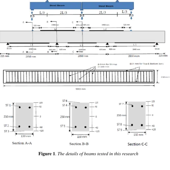
A total of six continuous reinforced concrete (RC) beams were cast and tested at Civil Engineering Laboratory in Reims University, France. The details of six RC beams and their configurations used in this work was shown in Fig.1, Fig, 2 and Table 1.
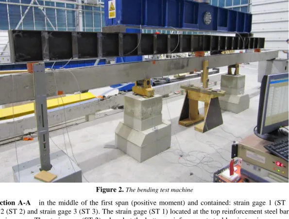
Figure 2. The bending test machine
Section A-A in the middle of the first span (positive moment) and contained: strain gage 1 (ST 1), strain gage 2 (ST 2) and strain gage 3 (ST 3). The strain gage (ST 1) located at the top reinforcement steel bar in the compression zone. The strain gage (ST 2) placed at the bottom reinforcement steel bar in tension zone, and the strain gage (ST 3) situated on the bottom face of the beam, it located on a concrete surface for the control beam and located on the strips of composite material for other beams.
Section B-B on the second support (negative moment) and contained: strain gage 4 (ST 4), strain gage 5 (ST 5) and strain gage 6 (ST 6). The strain gage (ST 4) located at the top reinforcement steel bar at the tension zone. The strain gage (ST 5) placed at the bottom reinforcement steel bar at the compression zone, and The strain gage (ST 3) situated on the top face of the beam, it located on a concrete surface for the control beam and located on the strips of composite material for other beams.
Section C-C in the middle of the of the beam on the second span (positive moment) contained: strain gage 7 (ST 7), strain gage 8 (ST 8) and strain gage 9 (ST 9).The strain gage (ST 7) located on the top reinforcement steel bar in the compression zone. The strain gage (ST 8) placed at the bottom reinforcement steel bar in the tension zone, and The strain gage (ST 9) situated on the bottom face of the beam, it located on a concrete surface for the control beam and located on the strips of composite material for other beams.
Table 1. The details of the beams
Group Continuous Beam Composite Materials Conditions Strips Number
Type of Resin Length of Strips
L1 L2 L3
Group 1
RCCG0 No Control beam 0 - - - -
RCCG1 GFRP 100% damaged 4 polyester 2.4 m 1.9 m 1.6 m
RCCG2 GFRP Not damaged 4 polyester 2.4 m 1.9 m 1.6 m
Group 2
RCCF0 No Control Beam 0 - - - -
RCCF1 CFRP 100 % damaged 2 Sikadur-330 2.4 m 1.9 m 1.6 m
3.2 Materials Properties
All the beams were cast using ready mix concrete with a compressive strength of 47 Mpa. For main internal reinforcement, it used 2ɸ16 at bottom and 2ɸ16 at the top and used ɸ8 for the stirrups each 100 mm. For this study, bi-directional Carbon-fiber-reinforced polymer (CFRP) sheet and glass sheet was used as external reinforcement and used epoxy Sikadur-330 for the CFRP sheet and the Resin ISO (UN 1866 class 3) for the Glass-fiber-reinforced polymer (GFRP) sheet.
4. Results and discussions
All beams were loaded with a concentrated load at the middle of each span as shown in (Fig.1). The experimental results were presented in Table 2. All the beams were tested under flexural load.
Table 2. The test results of all beams
G ro u p Beam Composite Materials Conditions First Crack Load kN Ultimate Load kN Contribution of Composite Material % Modes of Failure G ro u p 1
RCCG0 No Control beam 45 307 - flexural
RCCG1 GFRP 100% damaged 45 333 8.5 GFRP debonding
RCCG2 GFRP Not damaged 55 327 7.2 GFRP debonding
G
ro
u
p
2
RCCF0 No Control Beam 46 305 - Flexural
RCCF1 CFRP 100 % damaged 46 370 21 CFRP debonding
RCCF2 CFRP Not damaged 65 356 16.7 CFRP rupture
The control beam of the first group (RCCG0) which was not strengthened by GFRP sheet was tested and loaded up to fail. It was observed that flexural cracks appeared initially in the tension zone in the middle of the first span and the middle of the third span because of the symmetry at the load of 46 kN. Further, new cracks appeared in the tension zone at the two middle supports. After that, the cracks appeared in tension zone in the middle of the beam, the vertical cracks increased and became grander and propagated to the compression zone of the specimen as the load was increased till the failure load 307 kN. The other tested beams get the same response of the control beam of the first group in general but with a different value of the first cracking load and or failure load and or the mode of failure. The load-strain curve and the cracks patterns on the section A-A of each beam are shown in the following figures;
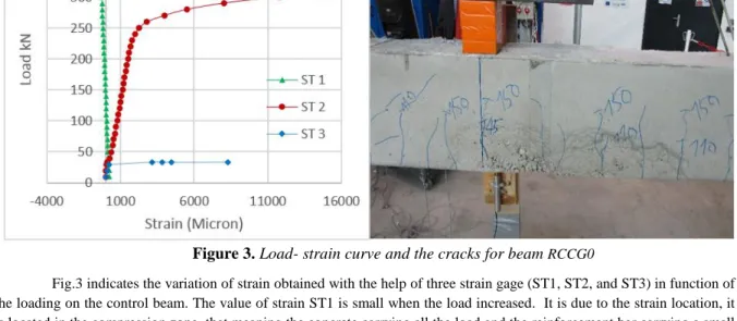
Figure 3. Load- strain curve and the cracks for beam RCCG0
Fig.3 indicates the variation of strain obtained with the help of three strain gage (ST1, ST2, and ST3) in function of the loading on the control beam. The value of strain ST1 is small when the load increased. It is due to the strain location, it is located in the compression zone, that meaning the concrete carrying all the load and the reinforcement bar carrying a small load .while the strain gage (ST2 increased linearly till the load reached 250 kN, that meaning the steel in the elastic zone.
After that, the strain rapidly increased till the failure load. The strain ST3 increased linearly till the load arrived at 30 kN and after that, the curve moved hormonally till the load arrived 33.5 kN at this moment the strain gage was broken. The photo shows the cracks in the concrete located at the section A-A and the failure mode is in flexural.
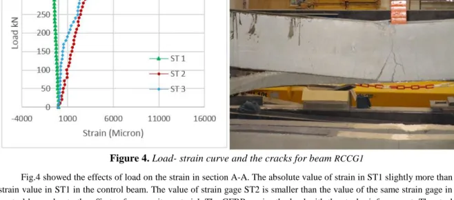
Figure 4. Load- strain curve and the cracks for beam RCCG1
Fig.4 showed the effects of load on the strain in section A-A. The absolute value of strain in ST1 slightly more than the strain value in ST1 in the control beam. The value of strain gage ST2 is smaller than the value of the same strain gage in the control beam due to the effects of composite material. The GFRP carries the load with the steel reinforcement. The steel reinforcement still linearly increased till the load reached to 330kN after that the steel bar was in yield zone.The value obtained by the strain gage ST3 increased as the load increased up to failure. In this case, the failure mode is also debonding.
Figure 5. Load- strain curve and the cracks for beam RCCF1
Fig.5 indicated the relation between the strain and the load. When the beam was cracked up to 100% and at that moment the strain gages ST1 and ST2 were damaged. The value of the strain (ST3) increased linearly till the load reached to 300 kN, after that the strain value was not changed till the load 330 kN because the steel was reached to the plastic limit. The maximum value of strain (ST3) in this beam is 4000 micron, and the maximum load is 370 kN but in the beam RCCG1, the maximum value was 4400 micron and the maximum load 333 kN. The failure mode of this beam was debonding.
Fig.6 shows the variation of strain in function of the load of the RC strengthened directly by GFRP without damaged the beam. It is interesting to note that the strain value obtained by ST1 is similar with that in the beam RCCG1 (Fig.3). This result shows that there is no difference in the strengthening effectiveness by using the GFRP between one RC beam damaged at 100% and the RC beam without damaged. The shape of the load-strain
curve obtained by ST2 is similar with that obtained by ST2 on the control beam (Fig.1). However, the ultimate values are different. In the case of the beam RCCG2, the maximum value is 9500 micron and for the beam
Figure 6. Load- strain curve and the cracks for beam RCCG2
RCCG0, the value is 15000 micron. The corresponding load is 326 kN and 305 kN, respectively. The cracks are in the tension zone, and the mode of failure is debonding as shown in the photo above.
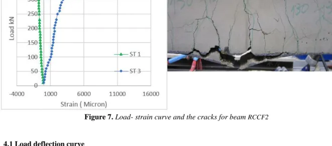
Fig.7 shows the load-strain relation for the beam RCCF2. This beam was strengthened with CFRP sheets without pre-cracking. There is not great difference on the variation of the strain value at the location of ST1 in comparison with those obtained on other beams. However, the strain gage ST2 was broken during the test. The maximal values of the strain obtained by ST3, corresponding to the ultimate load, is 5500 micron. The figure shows the failure of this beam is different; the rupture is due to the break of the CFRP sheets.
Figure 7. Load- strain curve and the cracks for beam RCCF2
4.1 Load deflection curve
The load deflection curve as shown in Fig.8 indicates that there are three zones for the mechanical behaviour of the continuous RC beams strengthened or retrofitted by composite materials. The first zone shows the load value varying between 0 and 35kN. In this zone, the RC beam is within the elastic limit. The second zone presents the load value varying between 35 and 280kN. In this zone, the first cracks appeared in the tension zone of concrete, and the steel bar stays in the elastic limit. In this zone, the steel bar principally carries the
loading. The third zone indicates that the load value varies from 280 kN up to failure loading. In this zone, in comparing with the control beam RCCG0, the total capacity of the beam RCCG2 increases 7.2 %. In the case of the beam RCCF2, the total capacity increases 21 %. Fig.8 also shows that strengthening or retrofitting by composite materials can increase the load capacity and decrease the ductility of the RC continuous beam.
Fig.8: Load -deflection curve (LVDT 1)
5. Conclusion
The main conclusions drawn from this study can be summarised as follows:
The effect of strengthening by the CFRP sheets is more significantly in comparison with the GFRP sheets. In this work, the total capacity increases 21% by using the CFRP and 7.2% by using GFRP. There is no great different between the beam strengthened and retrofitted by using CFRP or GFRP. The RC beam strengthened or repaired with GFRP sheets is more ducktail to the beam strengthened or
repaired with CFRP sheets.
It exists two modes of failure: failure due to the debonding and the rupture of the composite materials. References
[LIG 2007] Lignola, G. P., et al. "Experimental performance of RC hollow columns confined with CFRP." Journal of Composites for Construction 11.1 (2007): 42-49.
[FOR 2008] Foret, Gilles, and Oualid Limam. "Experimental and numerical analysis of RC two-way slabs strengthened with NSM CFRP rods." Construction and Building Materials 22.10 (2008): 2025-2030.
[CHE 2003] Chen, J. F., and J. G. Teng. "Shear capacity of FRP-strengthened RC beams: FRP debonding." Construction and Building Materials 17.1 (2003): 27-41.
[THO 2004] Thomsen, Henrik, et al. "Failure mode analyses of reinforced concrete beams strengthened in flexure with externally bonded fiber-reinforced polymers." Journal of composites for construction 8.2 (2004): 123-131.
[TOU 2006] Toutanji, H., L. Zhao, and Y. Zhang. "Flexural behavior of reinforced concrete beams externally strengthened with CFRP sheets bonded with an inorganic matrix." Engineering Structures 28.4 (2006): 557-566.
[RAB 2003] Rabinovitch, O., and Y. Frostig. "Experiments and analytical comparison of RC beams strengthened with CFRP composites." Composites part B: engineering 34.8 (2003): 663-677.
[HAS 2008] Hashemi, Seyed Hamid, Ali Alkbar Maghsoudi, and Reza Rahgozar. "Flexural ductility of reinforced HSC beams strengthened with CFRP sheets." Struct Eng Mech 30.4 (2008): 403-426.
[GRA 1999] Grace, Nabil F., et al. "Strengthening reinforced concrete beams using fiber reinforced polymer (FRP) laminates." ACI Structural Journal-American Concrete Institute 96.5 (1999): 865-874.
[SAA 1991] Saadatmanesh, Hamid, and Mohammad R. Ehsani. "RC beams strengthened with GFRP plates. I: Experimental study." Journal of Structural Engineering 117.11 (1991): 3417-3433.
[AN. 1991] An, Wei, Hamid Saadatmanesh, and Mohammad R. Ehsani. "RC beams strengthened with FRP plates. II: Analysis and parametric study." Journal of Structural Engineering 117.11 (1991): 3434-3455.
[WAG 2009] Wang, Yung-Chih, and Kai Hsu. "Design recommendations for the strengthening of reinforced concrete beams with externally bonded composite plates." Composite structures 88.2 (2009): 323-332.
[SPA 2001] Spadea, G., R. N. Swamy, and F. Bencardino. "Strength and ductility of RC beams repaired with bonded CFRP laminates." Journal of Bridge Engineering 6.5 (2001): 349-355.
[NEW 2002] Newamian. A., S. Setunge, and W. Lokuge. "Review of Strengthening Techniques Using Externally Bonded Fibre Reinforced Polymer Composites: Report 2002-005-C-01." CRC Construction Innovation (2002): 1-48.