HAL Id: hal-00337017
https://hal.archives-ouvertes.fr/hal-00337017
Submitted on 27 Aug 2018
HAL is a multi-disciplinary open access
archive for the deposit and dissemination of
sci-entific research documents, whether they are
pub-lished or not. The documents may come from
teaching and research institutions in France or
abroad, or from public or private research centers.
L’archive ouverte pluridisciplinaire HAL, est
destinée au dépôt et à la diffusion de documents
scientifiques de niveau recherche, publiés ou non,
émanant des établissements d’enseignement et de
recherche français ou étrangers, des laboratoires
publics ou privés.
Evolution of corrosion protection for sol-gel coatings
doped with inorganic inhibitors
Virginie Moutarlier, Bertrand Neveu, Marie Pierre Gigandet
To cite this version:
Virginie Moutarlier, Bertrand Neveu, Marie Pierre Gigandet. Evolution of corrosion protection for
sol-gel coatings doped with inorganic inhibitors. Surface and Coatings Technology, Elsevier, 2008, 202
(10), pp.2052-2058. �10.1016/j.surfcoat.2007.08.040�. �hal-00337017�
Evolution of corrosion protection for sol
–gel coatings doped
with inorganic inhibitors
V. Moutarlier
⁎
, B. Neveu, M.P. Gigandet
Institut UTINAM, UMR CNRS 6213, Equipe Sonochimie et Réactivité des surfaces, 16 route de Gray, 25 000 Besançon, France
One the way to improve the self-repair properties of sol–gel films on aluminium alloy is the addition of corrosion inhibitors which could be released from the coating, minimising the corrosion of the unprotected area. Environmentally friendly corrosion inhibitors are studied (chromium III, molybdate, permanganate and cerium III) and compared to the standard corrosion inhibitor, i.e. hexavalent chromium.
Corrosion performances are studied by polarisation resistance (Rp) in chloride medium. Evolution of composition of sol–gel coatings, during the corrosion test, is examined by GDOES (glow discharge optical emission spectroscopy).
The results show that the morphology of sol–gel and the solubility of the additive play a role in the effectiveness of corrosion protection for a long term. Additives such as molybdate and permanganate ions decrease the sol–gel network stability and are too soluble (they are rapidly lost from the sol–gel films, in an aggressive medium), decreasing the power to prevent corrosion. Incorporation of Ce III is not efficient for a long time due to its high solubility. Sol–gel films containing Cr VI and Cr III provide adequate corrosion protection, due to the sol–gel stability and their low solubility.
Keywords: Sol–gel; Inorganic corrosion inhibitor; Aluminium alloy; GDOES
1. Introduction
The sol–gel process is a method in which oxide films can be deposited on a substrate at much lower temperatures than traditional ceramic process methods [1]. A variety of metal alkoxides (M(OR)n, where R represents an organic group and M a
metal) can be used as precursors for the sol–gel synthesis. Upon deposition, the coating undergoes hydrolysis represented by the Eq. (1) and condensation corresponding to Eqs. (2) and (3)[2]:
Hydrolyse :MðORÞnþ H2O→MðORÞn−1ðOHÞ þ ROH ð1Þ Condensation :2MðORÞn−1ðOHÞ→ðORÞn−1M–O–MðORÞn−1þ H2O
ð2Þ MðORÞn−1ðOHÞ þ MðORÞn→ðORÞn−1M–O–MðORÞn−1þ ROH
ð3Þ One potential application of the sol–gel coatings is the pro-tection against corrosion of aluminium alloy surface [3–6].
Such use is principally conducted using alkoxides based on silane (M = Si, n = 4) and zirconium (M = Zr, n = 4). The sol–gel films must provide an excellent adhesion to the substrate and a suitable protection against corrosion by creating a chemically inert barrier between the substrate and the aggressive environment
[7]. However, these coatings cannot offer an adequate protection for a long term due to the presence of micro-pores, cracks and areas with low cross-link density. These zones favour the diffusion of aggressive species to the coating/substrate interface and are preferential sites of corrosion initiation[8,9]. In order to limit the corrosion process, corrosion inhibitors can be incorpo-rated into the sol–gel films. The doped sol–gel film acts as a reservoir of corrosion inhibitors that, in an aggressive medium, diffuse through the coating and become active for corrosion process. The combination of sol–gel network stability and inhibitor solubility will allow to provide a high corrosion protec-tion for a long term[3,10,11].
The most widely used and effective inhibitor is hexavalent chromium [12]. However, the use of Cr VI is becoming in-creasingly restrictive due to its characteristic as human carcinogen and substantial contribution to environmental pollution. Environ-mental friendly corrosion inhibitors for aluminium alloys, that
⁎ Corresponding author.
were found to have a significant inhibiting action on corrosion process, are trivalent chromium[13], molybdate ions[14], per-manganate ions[15]and cerium salts[16].
The objective of this study is to investigate the behaviour during the corrosion process of the doped sol–gel films. These hybrid films are prepared with tetramethoxysilane (TMEOS), methyltriethoxysilane (MTEOS) and gamma-glycidoxypropyl-methyldiethoxysilane (GPMDEOS) as a source of hydrolysable silane, tetra-propoxyzirconium (TPOZ) as a source of hydro-lysable zirconium, and various inorganic compounds as cor-rosion inhibitors (Cr VI, Cr III, Ce III, Mo VI and Mn VII). The anticorrosion behaviours of the sol–gel films are characterised by electrochemical measurement: polarisation resistance (Rp). The evolution of the coating composition during the corrosion process is followed by glow discharge optical emission spec-troscopy (GDOES).
2. Experimental
2.1. Substrate preparation
The substrate is 2017 aluminium alloy of composition (wt %): 92.3 Al, 4.2 Cu, 0.8 Mg, 0.8 Si, 0.7 Fe, 0.7 Mn, 0.3 Zn, 0.2 Ti[12]. The aluminium samples are soaked in an industrial acid cleaner solution, for 4 min, at 45 °C.
2.2. Synthesis and deposition of sol–gel films
The synthesis of the sol–gel solutions is performed by mixing reagents from Aldrich: tetramethoxysilane (TMEOS, 99%), methyltriethoxysilane (MTEOS, 90%), gamma-glycidoxypropyl-methyldiethoxysilane (GPMDEOS) and tetra-propoxyzirconium (TPOZ, 70% in propanol). The selected inorganic inhibitors are chromium VI used for comparison, chromium III, molybdate, permanganate and cerium III as potential substitutes. The form of the inhibitor salts is listed inTable 1. The toxicity of the alterna-tive inhibitors is lower than that of the hexavalent chromium, as shown inTable 1.
The first solution (solution A) is prepared by combining 6% TMEOS, 60% MTEOS, 20% GPMDEOS and 10% acidified
Table 1
Information concerning selected corrosion inhibitors
Inhibitor Cr VI Cr III Mo VI Mn VII Ce III Compound CrO3 Cr(NO3)3 Na2MoO4 KMnO4 Ce(NO3)3
Toxicity (LD50)⁎ 55 1790 570 1090 unknown
⁎LD50is the quantity that when ingested, injected, or applied to the skin as a single
dose will cause death of 50% of test animals. The value is expressed as mg kg− 1of body weight.
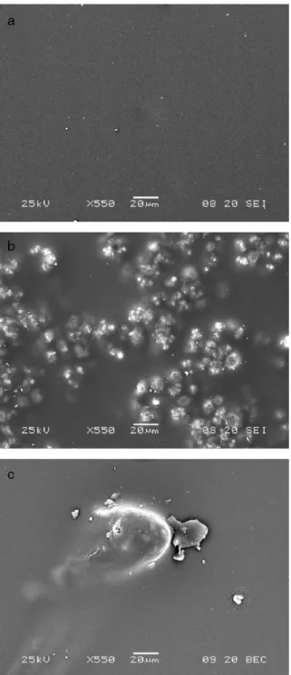
Fig. 1. SEM micrographs (× 550) of surfaces of the sol–gel films formed a) without
water (pH≈2) in volume. This mixture is stirred for 4 h. Then, 4% TPOZ in volume is added under vigorous stirring for 1 h. The second solution (solution B) is composed of acidified water (pH≈2) without or with 0.3 M inorganic inhibitors. The final sol–gel solution contains solution A/solution B/butanol in a 3/1.5/1 volume ratios.
The sol–gel films are produced by bare-coating. Bare-coating allows to form a thin film by a continuously moving of a bare on the substrate. After coating application, samples remain at room temperature during 30 min and are cured at 100 °C during 15 h. 2.3. Experimental techniques
The morphology of the sol–gel films is examined by scanning electron microscopy (SEM) with a JEOL model JSM 5600 operated at 22 kV.
The composition of the sol–gel coatings is studied by glow discharge optical emission spectroscopy (GDOES), using a Horiba Jobin Yvon GD Profiler[17]. The sol–gel coatings are placed as
cathode and are sputtered in an argon atmosphere by applying 60 W under 850 Pa. Light emission of characteristic wavelengths, associated with the sputtered species, is monitored throughout the analysis for depth profiling. The detected elements are Al (396 nm), O (130 nm), Si (288 nm), Zr (339 nm), C (156 nm), Cr (425 nm), Mo (386 nm), Mn (403 nm), Ce (413 nm). To evaluate the anti-corrosive properties of the doped sol–gel films the polarisation resistance method is used. Polarisation resistance values (Rp) are determined during the immersion in 5% NaCl solution. The electrochemical cell is composed of three electrodes: a saturated calomel electrode (SCE) as reference, a titanium sheet as auxiliary electrode and a coated aluminium alloy as working electrode with the exposed area of 2 cm2. A PGP 201
potentiostat–galvanostat under computer control is used. The general procedure is to apply a scan rate of 10 mV s− 1, with a signal amplitude of ±40 mV around the open circuit potential. Polarisation resistance is recorded at different times of immersion in the aggressive solution.
3. Results and discussion
3.1. Examination of doped sol–gel films 3.1.1. Morphology of doped sol–gel films
The SEM technique is used in order to observe the morphology of the different coatings. The thickness of coatings is estimated by cross-section analysis and is 7μm±1 μm. The surfaces of the sol– gel films without additive, with Cr VI, Cr III and Ce III seem to be crack-free and without defects. A representative SEM micrograph is shown inFig. 1a. Thus, in these cases, the organic/inorganic network is stable. On the contrary, particles clearly appear in the sol–gel surface containing Mo VI, as shown in Fig. 1b. The distribution of these particles is inhomogeneous and they have an average diameter around 10 μm. The agglomeration of these particles forms large aggregates (50μm). According a previous study[18], this inhibitor salt could be crystallised in the sol–gel
matrix or/and interfere with the condensation reaction, producing the disorganised sol–gel network. For the sol–gel film formed with Mn VII, few defects with a big size, around 40 μm of diameter, are observed (Fig. 1c). The brown colour of these defects indicates that it could be a manganese oxide precipitate. Thus, permanganate addition also disorganises the sol–gel network.
3.1.2. Composition of doped sol–gel films
The composition of the sol–gel coatings is investigated using the GDOES technique. GDOES profiles present the distribution of the detected elements versus the sputtering time[17].Fig. 2
shows the general GDOES depth profile of sol–gel films. The sol–gel/substrate interface is defined as the position where the Al signal increases. Thus, the sol–gel/substrate interface is at 60 seconds of analysis. The oxygen (× 2000), carbon (× 5),
silicium (× 5) and zirconium (× 50) elements characterise the organic coating. The magnifications are chosen to observe all elements in the same scan. Profile indicates that the distribution of the elements of the hybrid coating is uniform.
Sol–gel coatings are doped with inorganic corrosion inhibitors and the GDOES technique is able to detect these additives. The GDOES profiles inFig. 3correspond to the additive signal only. All sol–gel/substrate interfaces are at 60 s of analysis. This confirms that all coatings have the same thickness. For the sol–gel films doped with Cr VI, Cr III and Ce III, the additives Cr and Ce are homogeneously incorporated, as we can see with the profiles inFig. 3a, b and c, respectively. For the sol–gel film formed in
presence of Mo VI, the signal of molybdenum is inhomogeneous (Fig. 3d). This additive appears less incorporated in the outer part of the coating. The distribution of Mn element for the sol–gel film doped with Mn VII is complex since the substrate is composed of manganese (Fig. 3e). The signal of Mn during the first 60 s of analysis corresponds to the additive incorporated into the sol–gel matrix and the last 60 s to the manganese present in the aluminium alloy. Manganese species are incorporated relatively uniformly in the coating.
Fig. 4. Corrosion behaviour of undoped sol–gel film: polarisation resistance during the immersion in 5% NaCl solution.
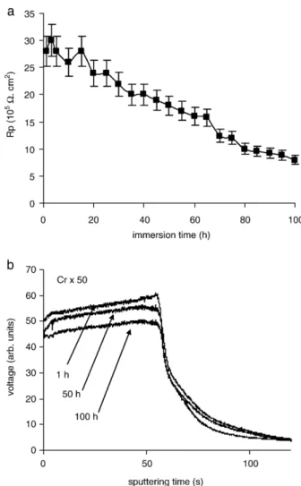
Fig. 5. Corrosion behaviour of sol–gel film doped with Cr VI: a) polarisation resistance and b) GDOES depth profiles of Cr, during the immersion in 5% NaCl solution.
3.2. Corrosion behaviours of doped sol–gel films
Polarisation resistance (Rp) measurements are realised in 5% NaCl solution, to estimate the corrosion behaviours of the different hybrid sol–gel coatings. GDOES technique is also used to followed the evolution of additives (Cr, Ce, Mo, Mn) at different periods of immersion.
3.2.1. Undoped sol–gel films
Fig. 4shows the evolution of the Rp for the undoped sol–gel
film, during the immersion in the aggressive medium. The Rp value is initially around 8 105Ω cm2and fast decreases with the immersion time to reach a constant value of 2 105Ω cm2. From about 25 h of immersion, pits appear on the surface of the sol– gel coating.
3.2.2. Sol–gel films doped with Cr VI
Addition of hexavalent chromium demonstrates significant improvement of corrosion protection (Fig. 5a). Indeed, initial Rp value is around 30 105 Ω cm2 and slowly decreases to 8 105Ω cm2at 100 h of immersion. Pits are not visualised after the corrosion test.
Fig. 5b corresponds to the GDOES Cr profiles realised at different periods of the corrosion test (1, 50 and 100 h of immersion). The Cr signal on the substrate part (after 60 seconds of analysis) is constant. Indeed, the composition of the aluminium alloy remains the same during the corrosion test. Thus, only the evolution of the Cr signal on the sol–gel part will be discussed. Additive signal slowly decreases during the corrosion test. This additive is still present in the sol–gel film after 100 h of immersion. This indicates a low solubility of hexavalent chromium from the hybrid film in an aggressive environment. Coating doped with Cr VI slowly releases the additive which becomes active for corrosion process. This sol– gel system holds enough additive for a long term protection[3]. 3.2.3. Sol–gel films doped with Cr III
An improvement of corrosion performance is also observed for coating doped with Cr III (Fig. 6a). This hybrid film shows high initial Rp, above 26 105Ω cm2. Then, Rp value decreases to 5 105Ω cm2at 100 h that is still higher than the final value for the undoped film. However, these Rp values indicate that this coating is less protective than the one doped with hexavalent chromium. This is confirmed by the presence of pits at 80 h.
Fig. 7. Corrosion behaviour of sol–gel film doped with Ce III: a) polarisation resistance and b) GDOES depth profiles of Ce, during the immersion in 5% NaCl solution.
Fig. 6. Corrosion behaviour of sol–gel film doped with Cr III: a) polarisation resistance and b) GDOES depth profiles of Cr, during the immersion in 5% NaCl solution.
Fig. 6b shows the evolution of the GDOES Cr signal realised at different periods of immersion. The decrease of the Cr signal is faster than for the coating doped with Cr VI. The trivalent chromium appears easier leached than the hexavalent chromium. 3.2.4. Sol–gel films doped with Ce III
The corrosion behaviour of sol–gel films formed with trivalent cerium is presented in Fig. 7a. At the beginning of corrosion test, the Rp values decrease from 13 to 3 105Ω cm2. Then, at 10 h of immersion, Rp values show fast increase until 15 105Ω cm2and finally decrease at 45 h to reach 6 105Ω cm2. Pits are visualised after 50 h of immersion.
The GDOES profiles of Ce during the immersion time are shown inFig. 7b. The Ce signal rapidly decreases during the corrosion test, indicating its diffusion through the sol–gel film. The inhibiting power of cerium appears after 10 h of immersion when the Rp values increase. As mentioned in previous works
[19–21], the cerium inhibiting effect is related to the plugging of corrosion products into the pores, causing the increase of corrosion resistance. However, after 50 h of corrosion test, the
most part of cerium ions is already released from the coating. Thus, the corrosion process could occur, explaining the decrease of Rp values and the apparition of pits after 50 h of immersion. The above results demonstrate an weak improve-ment of corrosion resistance and only for a short term, for the sol–gel film doped with Ce III[19–21].
3.2.5. Sol–gel films doped with Mo VI
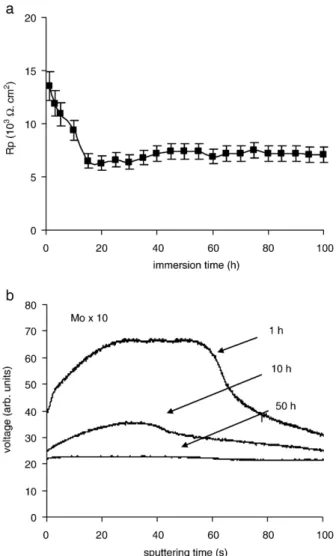
The sol–gel film doped with Mo VI presents the lowest corrosion resistance (Fig. 8a). Indeed, the Rp values rapidly decrease from 14 to 7 103Ω cm2that is significantly lower than for the undoped sol–gel film. Large pits are rapidly initiated in the sol–gel coating.
Fig. 8b shows the GDOES profiles of Mo during the immersion time. The signal of Mo rapidly decreases to be constant at 50 h of immersion. This indicates that Mo has completely disappeared from the sol–gel matrix. The poor corrosion protection could be due to the presence of big defects at the sol–gel surface (seeFig. 1b) and to the high solubility of this additive. The defects are preferential sites of pit initiation and
Fig. 8. Corrosion behaviour of sol–gel film doped with Mo VI: a) polarisation resistance and b) GDOES depth profiles of Mo, during the immersion in 5% NaCl solution.
Fig. 9. Corrosion behaviour of sol–gel film doped with Mn VII: a) polarisation resistance and b) GDOES depth profiles of Mn, during the immersion in 5% NaCl solution.
provide pathways for the diffusion of the corrosive species[9]. The high solubility induces that Mo VI could not act as corrosion inhibitor for a long time.
3.2.6. Sol–gel films doped with Mn VII
The evolution of Rp values for the sol–gel film formed with Mn VII (Fig. 9a) indicates an initially corrosion protection (Rp = 11 105 Ω cm2) closed to the undoped sol–gel coating, followed to a significant decrease of the corrosion resistance (Rp = 2 104 Ω cm2 at 100 h of immersion). Large pits are observed after 20 h of immersion in the aggressive medium. These pits are probably initiated on the big defects previously observed (seeFig. 1c).
The GDOES profiles of Mn at different immersion times are presented inFig. 9b. During the immersion, the Mn signal on the sol–gel part rapidly decreases, indicating a strong solubility of this additive. At the end of the corrosion test, the manganese is absent in the sol–gel matrix. As for the molybdenum species, the poor corrosion protection of the sol–gel doped with Mn VII could be explain by the presence of defects and the high solubility of this additive.
4. Conclusion
In order to improve corrosion protection for a long term, inorganic corrosion inhibitors have been incorporated into the sol–gel matrix. Polarisation resistance measurements have been employed to follow the corrosion behaviour in NaCl solution. GDOES analysis has been used to investigate the evolution of the composition of the sol–gel coatings, during the immersion in the aggressive medium.
The protection of the coating formed with hexavalent chromium, against the corrosive species, was efficient for a long term. Indeed, the absence of pits was noted after the corrosion test. GDOES analysis has shown that the chromium additive slowly released and could act durably on the corrosion process.
Various non-Cr VI corrosion inhibitors have been added to the hybrid coatings. Although the incorporation of chromium III has induced comparable corrosion behaviour than for the Cr VI, this additive has appeared easier leached. Thus, its protection for a long term seems to be slightly weaker. Incorporation of cerium III is not efficient due to its high solubility. Additions of molybdenum VI and magnesium VII did not provide an adequate corrosion protection due to the disorganisation of the sol–gel
systems (presence of particles and aggregates in the coating surface) and to the high solubility of these additives. The defects favoured the pit formation. The high solubility of the additive makes that the doped sol–gel films could not act as a reservoir for a prolonged release.
Structure of sol–gel film and solubility of the additive un-doubtedly play a role in the effectiveness of corrosion protection for a long term. However, an other parameter must be taken into account: the inhibiting power of each corrosion inhibitor. Thus, addition experiments are necessary to determine the mechanism of corrosion protection of these additives. This is the objective of the future work.
References
[1] R.L. Twite, G.P. Bierwagon, Prog. Org. Coat. 33 (1998) 91.
[2] C.J. Brinker, G.W. Scherer, Sol–Gel Science, Edited by Academic Press/ San Diego, (1990).
[3] J.H. Osborne, K.Y. Blohowiak, S.R. Taylor, C. Hunter, G. Bierwagon, B. Carlson, D. Bernard, M.S. Donley, Prog. Org. Coat. 41 (2001) 217. [4] N.N. Voevodin, N.T. Grebasch, W.S. Soto, L.S. Kasten, J.T. Grant, F.E.
Arnold, M.S. Donley, Prog. Org. Coat. 41 (2001) 287.
[5] X.F. Yang, D.E. Tallman, V.J. Gelling, G.P. Bierwagon, L.S. Kasten, J. Berg, Surf. Coat. Technol. 140 (2001) 44.
[6] M.L. Zheldukelvich, R. Serra, M.F. Montemor, I.M. Miranda Salvado, M.G.S. Ferreira, Surf. Coat. Technol. 200 (2004) 3084.
[7] T.L. Metroke, R.L. Parkhill, E.T. Knobbe, Prog. Org. Coat. 41 (2001) 233. [8] T.L. Metroke, A. Apblett, Prog. Org. Coat. 51 (2004) 36.
[9] N. Voevodin, C. Jeffcoate, L. Simon, M. Khobaib, M. Donley, Surf. Coat. Technol. 140 (2001) 29.
[10] Y.J. Du, M. Damron, G. Tang, H. Zheng, C.J. Chu, J.H. Osborne, Prog. Org. Coat. 41 (2001) 226.
[11] M. Quinet, B. Neveu, V. Moutarlier, P. Audebert, L. Ricq, Prog. Org. Coat. 58 (2007) 46.
[12] C. Vargel, Corrosion de l'aluminium, Edited by Dunod, (1999). [13] F. Pearlstein, V.S. Agarwala, Plating Surf. Finish. (1994) 50. [14] G.D. Wilcox, D.R. Gabe, M.E. Warwick, Corros. Rev. 6 (1986) 327. [15] H. Umehara, M. Takaya, S. Terauchi, Surf. Coat. Technol. 169-170 (2003)
666.
[16] P. Campestrini, Microstructure-related quality of conversion coatings on aluminium alloys, Edited by DUP Science, (2002).
[17] K. Shimizu, G.M. Brown, H. Habazaki, K. Kobayashi, P. Skeldon, G.E. Thompson, G.C. Wood, Electrochim. Acta 44 (1999) 2297.
[18] N.N. Voevodin, N.T. Grebasch, W.S. Soto, F.E. Arnold, M.S. Donley, Surf. Coat. Technol. 140 (2001) 24.
[19] A. Pepe, M. Aparicio, S. Cere, A. Duran, J. Non-Cryst. Solids 348 (2004) 162–171.
[20] M.L. Zheludkevich, R. Serra, M.F. Montemor, M.G.S. Ferreira, Electrochem. Commun. 7 (2005) 836–840.
[21] M.L. Zheludkevich, R. Serra, M.F. Montemor, K.A. Yasakau, I.M.M. Salvado, M.G.S. Ferreira, Electrochim. Acta 51 (2005) 208–217.