Publisher’s version / Version de l'éditeur:
Proceedings of the International Workshop on Scanning for Cultural Heritage
Recording - Complementing or Replacing Photogrammetry, pp. 58-64, 2002
READ THESE TERMS AND CONDITIONS CAREFULLY BEFORE USING THIS WEBSITE. https://nrc-publications.canada.ca/eng/copyright
Vous avez des questions? Nous pouvons vous aider. Pour communiquer directement avec un auteur, consultez la première page de la revue dans laquelle son article a été publié afin de trouver ses coordonnées. Si vous n’arrivez pas à les repérer, communiquez avec nous à PublicationsArchive-ArchivesPublications@nrc-cnrc.gc.ca.
Questions? Contact the NRC Publications Archive team at
PublicationsArchive-ArchivesPublications@nrc-cnrc.gc.ca. If you wish to email the authors directly, please see the first page of the publication for their contact information.
NRC Publications Archive
Archives des publications du CNRC
This publication could be one of several versions: author’s original, accepted manuscript or the publisher’s version. / La version de cette publication peut être l’une des suivantes : la version prépublication de l’auteur, la version acceptée du manuscrit ou la version de l’éditeur.
Access and use of this website and the material on it are subject to the Terms and Conditions set forth at
Detailed 3D Reconstruction of Monuments Using Multiple Techniques
El-Hakim, S.; Beraldin, J.-A.
https://publications-cnrc.canada.ca/fra/droits
L’accès à ce site Web et l’utilisation de son contenu sont assujettis aux conditions présentées dans le site LISEZ CES CONDITIONS ATTENTIVEMENT AVANT D’UTILISER CE SITE WEB.
NRC Publications Record / Notice d'Archives des publications de CNRC:
https://nrc-publications.canada.ca/eng/view/object/?id=a50eda15-ac9f-42cb-9e55-74148307ffbe
https://publications-cnrc.canada.ca/fra/voir/objet/?id=a50eda15-ac9f-42cb-9e55-74148307ffbe
National Research
Council Canada
Institute for
Information Technology
Conseil national
de recherches Canada
Institut de technologie
de l’information
Detailed 3D Reconstruction of Monuments Using
Multiple Techniques *
El-Hakim, S., and Beraldin, J.-A.
September 2002
* published in Proceedings of the Intern. Workshop on Scanning for Cultural Heritage
Recording - Complementing or Replacing Photogrammetry, Corfu, Greece.
September 01-02, 2002. pp.58-64. NRC 44915.
Copyright 2002 by
National Research Council of Canada
Permission is granted to quote short excerpts and to reproduce figures and tables from this report, provided that the source of such material is fully acknowledged.
1
DETAILED 3D RECONSTRUCTION OF MONUMENTS USING MULTIPLE
TECHNIQUES
Sabry F. El-Hakim, J.-Angelo Beraldin, Michel Picard
Visual Information Technology (VIT) Group
Institute For Information Technology, National Research Council Canada (NRC) Ottawa, Ontario, Canada K1A 0R6
E-mail: {Sabry.El-Hakim; Angelo.Beraldin; Michel.Picard}@nrc.ca
Commission V, Working Group V/2
KEY WORDS: Cultural Heritage, Laser scanning, Three-dimensional, Reconstruction, Texture, Virtual Reality, Registration
ABSTRACT:
The use of 3D digitization and modeling in documenting heritage sites has increased significantly over the past few years. This is mainly due to advances in laser scanning techniques, 3D modeling software, image-based-modeling techniques, computer power, and virtual reality. There are many approaches currently available. The most common remains based on surveying and CAD tools and/or traditional photogrammetry with control points and a human operator. This is very time consuming and can be tedious and sustained effort. Lately, modeling methods based on scanners data and more automated image-based technique are becoming available. We will discuss each approach and point out its advantages and disadvantages. We will then present our approach, which is a combination of several technologies. The approach presented in this paper uses both interactive and automatic techniques, each where it is best suited, to accurately and completely model heritage objects and sites. A highly detailed structure or site can be modeled at various levels of detail. Image-based modeling may be used for the basic shape and main structural elements, and laser scanning for fine details and sculpted surfaces. The results of applying this approach were very encouraging and several models were created from sites all over the world. Modeling of the Abbey of Pomposa near Ferrara, Italy, will be presented as an example.
1
ISPRS-CIPA Workshop, Corfu, Greece, Sept. 1-2, 2002
1. INTRODUCTION
Many cultural heritage applications require 3D reconstruction of real world objects and scenes. The motives are numerous:
1. To document historic buildings, sites, and objects for reconstruction or restoration if they are ever destroyed, for example by fire, earthquake, flood, war, or erosion. 2. To create education resources for history and culture
students and researchers.
3. To reconstruct historic monuments that no longer exist, or partially exist.
4. To Visualize scenes from viewpoints that are impossible in the real world due to size or surrounding objects. 5. To Interact with objects without risk of damage. 6. Virtual tourism and virtual museum.
In general, most applications specify a number of requirements: 1. High geometric accuracy
2. Capturing all details 3. Photo-realism 4. Full automation 5. Low cost 6. Portability
7. Flexibility in applications 8. Efficiency in model size
The order of importance of these requirements depends on the application, for example whether it is documentation or virtual museum, but in many all are important. A single system that satisfies all requirements is still in the future. In particular, accurately capturing all details with a fully automated system for a wide range of objects and scene remains elusive. For small and medium sized objects, up to the size of human or a statue, range-based techniques such as laser scanners can provide
accurate and complete details with high degree of automation [Beraldin et al, 1999], but being relatively new technology that is not produced in large quantities, they remain costly. They are also not portable enough for a single person to carry around and use in a manner similar to a video or digital camera. The resulting model can also be inefficient for large objects. Image based approaches entail widely available hardware and potentially the same system can be used for a wide range of objects and scenes. They are also capable of producing realistic looking models and those based on photogrammetry have high geometric accuracy. The issues that remain are the capture of details on unmarked and sculpted surfaces and full automation. Approaches that skip the geometric modeling step, such as image-based rendering [Kang, 1999], are good for visualization and limited walkthrough. However, the lack of geometric model impedes the accuracy and the freedom to render the environment from arbitrary viewpoints
Most documented projects on cultural heritage have used one method or another, whereas very few have used a combination of techniques. For example, a group from IBM [Bernardini et al, 2002] used a combination of structured light 3D sensing and photometric stereo to model Michelangelo’s Florentine Pietà. Combining laser scanning with image-based modeling and rendering [Sequeira et al, 2001] and image-based modeling with image-based rendering [Debevec et al, 1996] have also been reported. Our approach combines the following techniques:
• The basic shape and large regularly shaped details, like columns, blocks and archways, are constructed from high-resolution digital images. This is based on advanced photogrammetry with several automated features that take advantage of properties found in heritage structures.
• Fine geometric details, like sculpted and irregularly shaped surfaces, are obtained by laser scans. This is combined and integrated with the basic model created in the first step. • Visual details on the geometric model are obtained from
image textures and reflectance models.
• Far away scenes like landscapes, are completed with image-based rendering (IBR) or panoramas. This serves mainly to present the monument in its natural setting.
This combination of techniques will satisfy most requirements except that, at least for now, the cost is not as low as a fully image-based system.
The remainder of the paper is organized as follows. In section 2, an overview of 3D reconstruction techniques is presented. This will lead to a deduction in the third section that a combination of techniques is the logical answer to acquiring all the necessary details. This is followed by the proposed approach in section 4. Section 5 describes the modeling of the Abbey of Pomposa using this multi-technique approach. The paper concludes with a short discussion in section 6.
2. OVERVIEW OF 3D CONSTRUCTION TECHNIQUES
A standard approach to create a model is to build it from scratch using tools, such as CAD software, that offer building blocks in the form of primitive 3D shapes. Some surveying data, or measurements from drawings and maps will also be required. This geometry-based modeling technique is obviously time and effort consuming and impractical and costly for large-scale projects. The created model also has a computer-generated look rather than realistic look and does not include fine details or irregular and sculpted surfaces. Currently efforts are directed towards increasing the level of automation and realism by starting with actual images of the object or directly digitizing it with a laser scanner. Here is a summary of recent techniques.
2.1 Image-Based Modeling
Image based modeling entails widely available hardware and potentially the same system can be used for a wide range of objects and scenes. They are also capable of producing realistic looking models and those based on photogrammetry have high geometric accuracy. Three-dimensional measurement from images naturally requires that interest points or edges be visible in the image. This is often not possible either because a region is hidden or occluded behind an object or a surface, or because there is no mark, edge, or visual feature to extract. In objects such as monuments in their normal settings we are also faced with the restrictions of limited locations from which the images can be taken as well as the existence of other objects, shadows and illumination.
The ultimate goal of all 3D reconstruction methods is to satisfy the eight requirements listed in the previous section. Since this is not easy, they focus on some of the tasks at the expense of the others. Efforts to increase the level of automation became essential in order to widen the use of the technology. However, efforts to completely automate the process from taking images to the output of a 3D model, while promising, are thus far not always successful. The automation of camera pose estimation and computation of pixel 3D coordinates will be summarized. This procedure, which is now widely used in computer vision [e.g. Faugeras et al, 1998, Fitzgibbon et al, 1998, Pollefeys et al, 1999, Liebowitz, et al, 1999], starts with a sequence of images taken by un-calibrated camera. The system extracts
interest points, like corners, sequentially matches them across views, then computes camera parameters and 3D coordinates of the matched points using robust techniques. The first two images are usually used to initialize the sequence. It is important that the points are tracked over a long sequence to reduce the error propagation. This is all done in a projective geometry basis and is usually followed by a bundle adjustment, also in the projective space. Self-calibration to compute the intrinsic camera parameters, usually only the focal length, follows in order to obtain metric reconstruction, up to scale, from the projective one [Pollefeys et al, 1999]. Again, bundle adjustment is usually applied to the metric construction to optimize the solution. The next step, the creation of the 3D model, is more difficult to automate and is usually done interactively to define the topology and edit or post process the output. For large structures and scenes, since the technique may require a large number of images, the creation of the model requires a significant human interaction regardless of the fact that image registration and a large number of 3D points were computed fully automatically.
The most impressive results remain to be those achieved with highly interactive approaches. Rather than full automation, an easy to use hybrid system known as Façade has been developed [Debevec et al, 1996]. The method’s main goal is the realistic creation of 3D models of architectures from small number of photographs. The basic geometric shape of the structure is first recovered interactively using models of polyhedral elements. In this step, the actual size of the elements and camera pose are captured assuming that the camera intrinsic parameters are known. The second step is an automated matching procedure, constrained by the now known basic model, to add geometric details. The approach proved to be effective in creating geometrically accurate and realistic models of architectures. The drawback is the high level of interaction and the restrictions to certain shapes. Also since assumed shapes determine all 3D points and camera poses, the results are as accurate as the assumption that the structure elements match those shapes. Our method, although similar in philosophy, replaces basic shapes with a small number of seed points to achieve more flexibility and higher level of details. In addition, the camera poses and 3D coordinates are determined without any assumption of the shapes but instead by a full bundle adjustment, with or without self-calibration depending on the given configuration. This achieves higher geometric accuracy independent from the shape of the object.
The Façade approach has inspired several research activities to automate it. Werner and Zisserman, 2002, proposed a fully automated Façade-like approach. Instead of the basic shapes, the principal planes of the scene are created automatically to assemble a coarse model. Like Façade, the coarse model guides a more refined polyhedral model of details such as windows, doors, and wedge blocks. Since this is a fully automated approach, it requires feature detection and closely spaced images matching and camera pose estimation using projective geometry. Dick et al, 2001, proposed another automated Façade-like approach. It uses model-based recognition to extract high-level models in a single image then project them into other images for verification. The method requires parameterized building blocks with a priori distribution defined by the building style. The scene is modeled as base planes corresponding to walls or roofs; each may contain offset 3D shapes that model common architecture elements such as windows and columns. Again, the full automation necessitates feature detection and projective geometry approach.
2.2 Range-Based Modeling
As mentioned above, three-dimensional measurement from images requires that interest points or edges be visible in the image, which is not always possible. They are also affected by the illumination or ambient light problems. Active sensors (e.g. laser scanners) [Besl, 1988, Rioux et al, 1987] avoid these limitations by creating features on the surface by controlled projection of light. They have the advantage of acquiring dense 3D points automatically. Recent advances in laser, CCD technology, and electronics made possible detailed shape measurements with accuracy better than 1 part per 1000 at rates exceeding 10,000 points per second. The scanning and imaging configuration determine the point density. Many also produce organized points, in the form of array or range image, suitable for automatic modeling. A single range image is usually not sufficient to cover an object or a structure. The amount of necessary images depends on the shape of the object, amount of self-occlusion and obstacles, and the object size compared to the sensor range. The 3D data must be registered in a single coordinate system. Several registration techniques are available; most are based on the iterative closest point (ICP) approach. For the approach to converge to the correct solution, it needs to start with the images approximately registered. This will require either the knowledge of sensor positions or manual registration using features. Once the range images are registered in a single coordinate system, they can be used for modeling. This step reduces the large number of 3D points into triangular mesh that preserves the geometric details and at the same time suitable for fast rendering [Curless and Levoy, 1996, Soucy et al, 1995]. In this process, the areas where the images overlap must be integrated to create a non-redundant mesh. Other requirements include filling of holes and removal of any outliers.
There are two main types of range sensors. The first is triangulation-based that projects light in a known direction from a known position, and measure the direction of returning light through its detected position. The accuracy of measurements will of course depend on the triangle base relative to its height. Since, for practical reasons, the triangle base is rather short, triangulation-based systems have a limited range of less than 10 meters (most are less than 3 meters). The second sensor type is based on the time-of-flight. Those measure the delay between emission and detection of the light reflected by the surface, and thus the accuracy does not deteriorate rapidly as the range increases. Time-of-flight sensors can provide measurements in the kilometer range.
Notwithstanding the advantages of range sensors, we should mention some drawbacks. They can be costly, bulky, affected by surface reflective properties, and may be complex to operate and calibrate. Also a range sensor is intended for a specific range, thus one designed for close range may not be suitable for long range. Comparative evaluation of image-based and range-based methods can be found elsewhere [El-Hakim et al, 1995].
2.3 Image-Based Rendering
In image-based rendering (IBR), images are used directly to generate new views for rendering without a geometric model [e.g. Kang, 1999]. This has the advantage of creating realistic looking virtual environment at speeds independent of scene complexity. The technique relies on automatic stereo matching that, in the absence of geometric data, requires a large number of closely spaced images to succeed. The required computations may need high processing power and large memory. Object occlusions and discontinuities will also affect the output. The
ability to move freely into the scene and viewing objects from any position will be limited without a geometric model. It is therefore unlikely that IBR will be the approach of choice for purposes other than visualization. For tourists where general visualization is enough, this approach may be adequate, but for historians and researchers, and of course for documentation, geometric details are needed.
3. COMBINING MULTIPLE TECHNIQUES
From the above summary of current techniques, it is obvious that none by itself can satisfy all the requirements of culture heritage applications. Given that:
• Although laser scanning will provide all the details, it is usually not practical to implement as the only technique for every object and structure. Large buildings for example will require a large number of scans and produce huge number of points even on flat surfaces.
• Image-based modeling alone will have difficulty with irregular and sculpted surfaces. Also it is important to develop an approach that requires only a small number of widely separated views and at the same time offers a high level of automation and be able to deal with occluded and unmarked surfaces.
(A)
(B)
Figure 1: Combined image-based and laser scanning methods. (A) The Abbey of Pomposa. (B) Dazu, China
Therefore, combining techniques where the basic shapes are determined by image-based methods and fine details by laser scanning is the logical solution. This is best described by an example. In figure 1, most of the structure is easy to model by images taken with a digital camera. However, parts of the surface contain fine geometric details that will be very difficult or impractical to model from images, such as the enlarged sections shown. Those parts are best acquired by a laser scanner and added to the global model created from the images. This involves matching and integrating local detailed points obtained by the scanner to the global model. We measure several features, usually six, using the images then extract the 3D coordinates of the same features from the scanned data. This is done interactively using intensity images generated by the laser
scanner. The transformation parameters are then used to register the two coordinate systems of the two data sets. The details of each approach and the combined approach will be described next.
4. DETAILS OF THE APPROACH
4.1 Image-Based Modeling
The approach is designed mainly for man-made objects such as classical architectures, which are designed within constraints of proportion and configurations. Classical buildings are divided into architectural elements. These elements are logically organized in space to produce a coherent work. There is a logical hierarchical relation among building parts and between parts and whole. The most common scheme divides the building into two sets of lines forming a rectangular grid [Tzonis and Lefaivre, 1986]. The distance between the grid lines are often equal or when they vary, they alter regularly. The grid lines are then turned into planes that partition the space and control the placement of the architectural elements. The automation of 3D reconstruction is better achieved when such understanding is taken into account. We will reconstruct the architecture elements from minimum number of points and put them together using the planes of a regular grid. Other schemes, such as a polar grid, also exist but the basic idea can be applied there too. Classical architecture can be reconstructed, knowing its components, even if only a fragment survives or seen in the images. For example, a columnar element consists of: 1) The capital, a horizontal member on top, 2) the column itself, a long vertical tapered cylinder, 3) a pedestal or a base on which the column rests. Each of those can be further divided into smaller elements. In addition to columns, other elements include pillars, pilasters, banisters, windows, doors, arches, and niches. Each can be reconstructed with a few seed points from which the rest of the element is built.
Our approach is photogrammetry-based. The approach does not aim to be fully automated nor completely rely on human operator. It provides enough level of automation to assist the operator without sacrificing accuracy or level of details. Figure 2 summarizes the procedure and indicates which step is interactive and which is automatic (interactive operations are light gray). The figure also shows an option of taking a closely-spaces sequence of images, if conditions allow, and increase the level of automation. Here, we will discuss only the option of widely separated views. Images are taken, all with the same camera set up, from positions where the object is suitably showing. There should be a reasonable distance, or baseline, between the images. Several features appearing in multiple images are interactively extracted, usually 12-15 per image. The user points to a corner and labels it with a unique number and the system will accurately extract the corner point. Harris operator is used [Harris, 1998] for its simplicity and efficiency. Image registration and 3D coordinate computation are based on photogrammetric bundle adjustment for its accuracy, flexibility, and effectiveness compared to other structure from motion techniques [Triggs et al, 2000]. Advances in bundle adjustment eliminated the need for control points or physically entering initial approximate coordinates. Many other aspects required for high accuracy such as camera calibration with full distortion corrections have long been solved problems in Photogrammetry and will not be discussed in this paper.
We now have all camera coordinates and orientations and the 3D coordinates of a set of initial points, all registered in the same global coordinates system. The next interactive operation
is to divide the scene into connected segments to define the surface topology. This is followed by an automatic corner extractor, again the Harris operator, and matching procedure across the images to add more points into each of the segmented regions. The matching is constrained, within a segment, by the epipolar condition and disparity range setup from the 3D coordinates of the initial points. The bundle adjustment is repeated with the newly added points to improve on previous results and re-compute 3D coordinate of all points.
Figure 2. General procedure for image-based modeling An approach to obtain 3D coordinates from a single image is essential to cope with occlusions and lack of features. Several approaches are available [e.g. van den Heuvel, 1998, Liebowitz et al, 1999]. Our approach uses several types of constraints for surface shapes such as planes and quadrics, and surface relations such as perpendicularity and symmetry. The equations of some of the planes can be determined from seed points previously measured. The equations of the remaining plane are determined using the knowledge that they are either perpendicular or parallel to the planes already determined. With little effort, the equations of the main planes on the structure, particularly those to which structural elements are attached, can be computed.
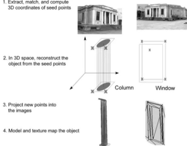
Figure 3. Main steps of constructing architectural elements semi-automatically (column and window examples)
From these equations and the known camera parameters for each image, we can determine 3D coordinates of any point or pixel from a single image even if there was no marking on the surface. When some plane boundaries are not visible, they can
be computed by plane intersections. This can also be applied to surfaces like quadrics or cylinders whose equations can be computed from existing points. Other constraints, such as symmetry and points with the same depth or same height are also used. The general rule for adding points on structural elements and for generating points in occluded or symmetrical parts is to do the work in the 3D space to find the new points then project them on the images using the known camera parameters. The main steps are shown in figure 3. We will now give some details on the use of seed points.
A cylinder is constructed after its direction, radius, and position have been automatically determined from four seed points (figure 4-a) using quadric formulation [Zwillinger, 1996]. The ratio between the upper and the lower circle can be set in advance. It is set to less than 1.0 (about 0.85) to create a tapered column. From this information, points on the top and bottom circle of the column (figure 4-b) can be automatically generated in 3D resulting in a complete model.
(a) (b)
Figure 4. (a) Four seed points are extracted on the base and crown, (b) column points are added automatically.
For windows and doors we need three (preferably four) corner points and one point on the main surface (figure 3). By fitting a plane to the corner points, and a plane parallel to it at the surface point, the complete window or door is reconstructed. For details on other elements, see [El-Hakim, 2002].
4.2 Range-Based Modeling
The procedure for creating a triangular-mesh model from 3D images is summarized in figure 5. If the 3D data is presented as a set of registered images it is trivial to create a triangular mesh by simply triangulating each image. However, since there is often considerable overlap between the images from different views, a mesh created in this fashion will have many redundant faces. It is desirable to create a non-redundant mesh, in which there are no overlapping faces. The adopted technique has been developed over the years at our laboratory and Innovmetric Software Inc. [Soucy and Laurendeau, 1995] and has been implemented in PolyworksTM [Innovmetric, 2002].
Figure 5: General procedure for range-based modeling
Most laser scanners focus only on acquiring the geometry. They usually provide only a monochrome intensity values for each pixel as sensed by the laser. To acquire realistic look for the model, texture maps obtained from high-resolution color digital camera is necessary. Some scanners have a color camera attached to the scanner at a known configuration so that the acquired texture is always registered with the geometry. However, this approach may not provide the best results since the ideal conditions for taking the images may not coincide with those for scanning. Therefore, our approach allows taking the images at different time from scanning and at whatever locations that will be best for texture. Details of the texturing procedure are described in another paper [Beraldin et al, 2002].
4.3 Combining Image- and Range-Based Modeling
First the model of the whole structure, except for the fine details and sculpted surfaces, is modeled using the image-based approach (section 4.1). The sections that require scanning will be modeled separately using the approach described in section 4.2. Common points between the image-based model and the range-based models are used to register them in the same coordinate system. This is done interactively with our own software that can display and interact with images from various types of sensors and cameras. The next step is to automatically sample points from the range-based model along its perimeter and insert those into the image-based model. The triangulated mesh of the image-based model will be adjusted based on those new points so that when the range-based model is added into that region there will be no overlapping triangles. This will be shown in the case study in section 5.
4.4 Landscape Visualization
When images of the whole scene taken at large distances such as aerial images are available, panoramic images of the landscape can be created and integrated with the model of the structures. This shows the structures in their natural setting and increases the level of realism. A few joint points between the structures and the grounds are measured in 3D to be used to register the panorama with the structures. The procedure is similar to [Sequeira et al, 2001].
5. MODELING THE ABBEY OF POMPOSA
The abbey of Pomposa near Ferrara, one of the most appealing Italian churches of the Romanesque period, is a complex made of several buildings that are part of one of the most important Benedectine monasteries. Founded in the seventh century, the Refectory, the Basilica, the Capitolary Hall and the Cloister form the core of the abbey. The bells tower was added in the eleventh century. The abbey is architecturally simple with planar stone surfaces. The façade is ornamented with several relief works of art carved in marble. There are also three arches decorated with brick and stonework.
Details like the left wheel “rosone”, the peacock carvings on the left side, and one end column (figure 6) were scanned with the Biris 3D sensor [Beraldin et al, 1999]. The whole complex was imaged with an Olympus 4 mega-pixel digital camera. Figure 7 shows the model of the front of the church with the main structural elements. Figure 8 shows a close up of the general model with added 8 new points from the trim of the wheel and the re-triangulated mesh. The hole shown in the model is where the model of the scanned wheel will fit. Figure 9 shows the detailed solid model, without texture, of the wheel and the
peacock after being added to the main model. A close up on part of the middle of the wheel showing a detailed wire frame is given in figure 10. The textured model of the same section is shown in figure 11. It is clear that the quality of the detailed scanned sections (1 and 2, figure 11) is much higher than the image-based regions (3 and 4), which lack the small geometric details. It is particularly more convincing when viewing these sections up close while navigating through the model.
Figure 6: Textured model of the front building showing the regions that were scanned.
Figure 7: The main architecture elements of the entrance of the Abbey created by image-based modeling.
.
Figure 8: Added trim points and re-meshing basic model.
Figure 9: Model of scanned left-side wheel and peacock.
Figure 10: Close up on the wire-frame model of part of the middle of the wheel.
Figure 11: Close up on the textured model. Sections 1 and 2 are scanned details, 3 and 4 are image based.
6. CONCLUDING REMARKS
A multi-technique approach to creating detailed 3D models of cultural heritage sites, classical architectures, and monuments was presented. It combines image-based and range-based modeling as well as image-based rendering. The image-based modeling is a semi-automatic approach that is designed specifically to take advantage of properties and arrangements common to such objects. A representative example, the Abbey of Pomposa near Ferrara, Italy, was demonstrated. In this example, the main structural elements were reconstructed from a small number of images while a laser scanner acquired the irregular shapes and fine details. In the image-based approach, parts of the process that can straightforwardly be performed by humans, such as registration, extracting seed points, and topological segmentation, remain interactive. Numerous details plus the occluded and the un-textured parts are added automatically by taking advantage of some of the object characteristics and making some realistic assumptions about the elements shapes and the relations between them. Modeling of the scanned sections was carried out fully automatically while its registration with the full image-based model was interactive. Current and near future activities focus on increasing the level of automation and ease of use of the approach, and applying it to a wide range of projects all over the world.
Acknowledgements
The authors acknowledge the help of Prof. Ing. Marco Gaiani (now at the Politecnico di Milano), late Architect Roberta Marchetti, and Architect Francesca Pozzi, who organized the survey campaign. Architects Anna Maria Iannucci and Andrea Alberti from the Soprintendente per i Beni Architettonici e del Paesaggio delle Provincie di Ravenna, Ferrara, Forlì-Cesena, Rimini are also acknowledged for giving us the opportunity to demonstrate our technology in Pomposa.
References
Beraldin, J.-A., F. Blais, L. Cornouyer., M. Rioux, S.F. El-Hakim, R. Rodella, F. Bernier, N. Harrison, 1999. 3D imaging system for rapid response on remote sites. IEEE proc. of 2nd. Int. Conf. 3D Digital Imaging and Modeling, pp. 34-43.
Beraldin, J.-A., Picard, M., El-Hakim, S., Godin, G., Latouche, C., Valzano, V., Bandiera, A., 2002. Exploring a Byzantine crypt through a high resolution texture mapped 3D model: combining range data and photogrammetry. ISPRS/CIPA Int. Workshop Scanning for Cultural Heritage Recording – Complementing or Replacing Photogrammetry. Corfu, Greece.
Bernardini, F., Rushmeier, H., Martin, I.M., Mittleman, J., Taubin, G., 2002. Building a digital model of Michelangelo's Florentine Pieta. IEEE Computer Graphics and Applications, 22(1), pp.59-67.
Besl, P.J., McKay, N.D., 1992. A method for registration of 3-d shapes. IEEE Transaction PAMI, 14(2), pp. 239-256.
Besl, P.J., 1988. Active, optical range imaging sensors.
Machine Vision and Applications, 1(2), pp. 127-152.
Curless, B., Levoy, M., 1996. A volumetric method for building complex models from range images. Proc. SIGGRAPH ‘96, pp. 303-312.
Debevec, P., C.J. Taylor, J. Malik, 1996. Modeling and rendering architecture from photographs: A hybrid geometry and image-based approach. SIGGRAPH’96, pp. 11–20.
Liebowitz, D., A. Criminisi, A. Zisserman, A., 1999. Creating Architectural Models from Images. EUROGRAPHICS ’99, 18(3).
Dick, A.R., P.H.Torr, S.J. Ruffle, R.Cipolla, 2001. Combining single view recognition and multiple view stereo for architectural scenes. Proc. 8th IEEE International Conference on Computer Vision (ICCV'01), pp. 268-274, July.
El-Hakim, S.F., Beraldin, J.-A.. 1995. Configuration analysis for sensor integration. Proc. SPIE Vol. 2598. Videometrics IV, pp. 274-285.
El-Hakim, S.F., 2002. Semi-automatic 3d reconstruction of occluded and unmarked surfaces from widely separated views. Proc. ISPSRS Commission V Symposium, Corfu, Greece, Sept.
Faugeras, O., L. Robert, S. Laveau, G. Csurka, C. Zeller, C. Gauclin, I. Zoghlami, 1998. 3-D reconstruction of urban scenes from image sequences. Computer Vision and Image
Understanding, 69(3), pp 292-309.
Fitzgibbon, A.W., Zisserman, A., 1998. Automatic camera recovery for closed or open image sequences. European Conf. On Computer Vision (ECCV’98), vol. 1, pp. 311-326.
Harris C., M. Stephens, 1998. A combined corner and edge detector. Proc. 4th Alvey Vision Conf., pp. 147-151.
Innovmetric Software Inc., 2002. http://www.innovmetric.com
Kang, S.B., 1999. Survey of image-based rendering techniques. SPIE Vol. 3641, Videometrics VI, pp. 2-16.
Pollefeys, M., R. Koch, L. Van Gool, 1999. Self-calibration and metric reconstruction in spite of varying and unknown intrinsic camera parameters. Int. J. of Computer Vision, 32(1), pp. 7-25.
Rioux, M., Bechthold, G., Taylor, D., Duggan, M., 1987. Design of a large depth of view three-dimensional camera for robot vision," Optical Engineering, 26(12), pp. 1245-1250.
Sequeira, V., Wolfart, E., Bovisio, E., Biotti, E., Goncalves, J.G., 2001. Hybrid 3D reconstruction and image-based rendering techniques for reality modeling. SPIE Vol. 4309, Videometrics and Optical Methods for 3D Shape Measurement, pp. 126-136.
Shum, H.Y., R. Szeliski, S. Baker, M. Han, P. Anandan, , 1998. Interactive 3D modeling from multiple images using scene regularities. Eur. Workshop 3D Structure from Multiple Images of Large-scale Environments – SMILE, pp 236-252.
Soucy, M., Laurendeau, D., 1995. A general surface approach to the integration of a set of range views. IEEE Transactions on
PAMI, 17(4), pp. 344–358.
Triggs, W., P. McLauchlan, R. Hartley, A. Fitzgibbon, 2000. Bundle Adjustment for Structure from Motion. in Vision
Algorithms: Theory and Practice, Springer-Verlag.
Tzonis, A., Lefaivre, L., 1986. Classical Architecture – The
Poetics of Order. MIT Press, Cambridge, MA.
van den Heuvel, F.A., 1998. 3D reconstruction from a single image using geometric constraints. ISPRS Journal
Photogrammetry & Remote Sensing, 53(6), pp. 354-368.
Werner, T., Zisserman, A., 2002. New technique for automated architectural reconstruction from photographs. Proc. 7th European Conf. Computer Vision, Copenhagen, May.
Zwillinger, D. (ed.), 1996. Standard Mathematical Tables. 30th Edition, CRC Press, Inc., Florida, pp 311-316.