Carbon Nanotube Based Electromechanical Probes
by
Onnik Yaglioglu
B.S., Bogazici University (1999)
S.M., Massachusetts Institute of Technology (2002)
S.M., Massachusetts Institute of Technology (2004)
Submitted to the Department of Mechanical Engineering
in partial fulfillment of the requirements for the degree of
Doctor of Philosophy
at the
MASSACHUSETTS INSTITUTE OF TECHNOLOGY
June 2007
@
Massachusetts Institute of Technology 2007
Sign tur ofA ut or .... . . ... .. ... ... ... ... .. Signature of Author
.
Mcial
Engineering
20 May 2007
Certified by
....
:.-...
...
...
Alexander H. Slocum
Professor of Mechanical Engineering, MacVicar Faculty Fellow
Thesis Supervisor
A ccepted by ... A ... I...- ...
SETTs
INSTITUTE
Lallit Anand
CHNOLOGY
Chairman, Department Committee on Graduate Students
MASSACHUOF TE
JUL
18
2007
Carbon Nanotube Based Electromechanical Probes
byOnnik Yaglioglu
Submitted to the Department of Mechanical Engineering on 20 May 2007, in partial fulfillment of the
requirements for the degree of Doctor of Philosophy
Abstract
Electromechanical probing applications continuously require smaller pitches, faster manufactur-ing and lower electrical resistance. Conventional techniques, such as MEMS based cantilever probes have their shortcomings in terms of the lowest pitch that can be achieved, cost and yield. Given their promising mechanical and electrical properties, carbon nanotubes (CNTs) are strong candidates for future probing applications. A new class of metal-CNT hybrid electro-mechanical probes is presented where vertically aligned carbon nanotube structures, grown with a chemical vapor deposition (CVD) technique, act as elastic springs, and a metal coating on the probes is used for increased electrical conduction. This design and architecture presents a scalable approach where thousands of probes can be fabricated in very short production times. 1.5 Ohm resistance and reliable performance for 6000 cycles at 50 ,im over-travel was achieved for a column of 200pmx200pzm cross-section and lpm of Au deposition. In-situ scanning elec-tron microscope mechanical compression tests revealed a unique deformation mechanism of the CNT structures where continued compression results in successive buckle formation which later can serve as micro-bellows and elastic springs. A novel stiffness tuning method is presented to control the elastic properties of a given CNT probe by controlling the initial compressing amount. Further stiffness tuning is achieved by changing gas composition during CVD growth where CNT diameter and density is modified. Lateral compression and densification tests show that these CNT structures are highly anisotropic and have very different deformation mecha-nisms in vertical and lateral directions. Mechanical properties resulting from two main CVD growth techniques, namely fixed catalyst where a thin film of catalyst layer is deposited onto the growth substrate, and floating catalyst where the catalyst particles are introduced in the gas phase, are compared. It is found that floating catalyst CVD growth yields much stiffer structures due to the relatively larger CNT diameters. As the adhesion of CNT structures to the growth substrate is very weak and the support layer is typically an insulator, a versatile transfer printing technique is developed which enables simultaneous placement and reinforce-ment of the probes on a wide range of substrates, including metals and printed circuit boards. Electromechanical performance and failure mechanisms of fully functional metal-CNT hybrid probes are presented.
Thesis Supervisor: Alexander H. Slocum
Acknowledgements
I have so many people to acknowledge who supported me along this long and winding road that I fear I will certainly miss someone. Many thanks to:
" Prof. Alex Slocum for being a very supportive and enthusiastic advisor, and a great friend.
" NSF and FormFactor Inc. for supporting my PhD project.
" Rod Martens from FormFactor Inc. for his continuous support and advice.
" John Gritters, Ben Eldridge and Igor Khandros from FormFactor Inc. for their support.
" My thesis committee: Profs. Jeff Lang, Brian Wardle, Carl Thompson and Jing Kong for their valuable comments and support.
" Colleagues at FormFactor Inc. who played a very important role in the completion of this thesis: Mike Harburn, Treliant Fang, Gaetan Mathieu, Mike Armstrong, Jim Williams, Brian Benson, Deborah Lawson, Jerry Tran, David Wang, Sangtae Park, Zhijun Zao, Sam Tor, Daniel Ngo, Huong Vu, Steven Uchimura, Simon Ko, Rigo Deleon, Rey Mercado, Randy Havener, Steve Van Tessel, Shoua Lo, Dominic Trucetta, Randy Drake (Therma), Scott Hansen (Therma), Mike (Therma), John (Therma), Pete Conrad, Robert Hernan-dez, Art Beverleigh (TPI Systems), Jason Martinez, Scott Hauser.
* Colleagues at University of Hawaii for the fruitful collaboration: Prof. Cao, Garret Minoru Hashiro and Xianglong Li.
" Colleagues at MIT for their technical support: Kurt Broderick, Enrique Garcia, Manu Prakash, Patrick Boisvert, Tony Garret, Jae-Bum Joo.
" Staff at MIT for their tremendous help over the years: Leslie Regan and Maureen Lynch.
" Prof. Y.M. Chiang for sharing his laboratory for our nanotube growth facilities.
" Colleagues at PERG lab and TELAMS for their support.
" Alex Buxman from FEI for his help with in-situ SEM videos and FIB cutting.
" My parents Nisan and Iris Yaglioglu for their love, support, and for sacrificing so much from their life for my education since elementary school.
" My brother Burag Yaglioglu for being my best friend and for his incredible support.
" My ex-girlfriend Maral Bal for her love and support during the initial years of graduate school and the period when I was preparing for the qualifiers.
" Hachikian family for their love and support.
" My wonderful extended family for their love.
* My roommates Jason, Suzanne and April for being great roommates.
" Vahe Caliskan for his friendship, support and advice throughout graduate school.
" Kirk Bozdogan for his continuous support.
Contents
1 Introduction
1.1 Carbon Nanotubes and Motivation for Probing Applications . . . . . 1.2 Objective, Scope, Contributions and Organization of the Thesis . . .
2 Carbon Nanotube Growth Methods and Column Manufacturing 2.1 CNT Growth Techniques
2.2 2.3 2.4 2.5
Fixed Catalyst CVD Grow Floating catalyst CVD Grc Comparison of CVD Methc Fabrication of CNT Colum . . . 2 7 th System . . . 28 iwth System . . . 33 d s . . . 34 n s . . . 36
3 Mechanical Characterization of Vertically tures; 3.1 Experimental Setup and Testing Issues . 3.1.1 Tribometer ... 3.1.2 In-Situ SEM Compression ... 3.2 Deformation Mechanism of CNT Columns 3.2.1 Initial Observations . . . . 3.2.2 In-situ SEM Compression . . . . . 3.2.3 Detailed Testing with Tribometer . 3.2.4 Modeling and Analysis . . . . 3.2.5 Effect of Column Area on Stiffness Aligned Carbon Nanotube Struc-Grown 41 . . . 4 1 . . . 42
. . . . 44
with Fixed Catalyst CVD . . . 46
. . . 46
. . . 49
. . . 51
. . . 59
. . . 62 3.2.6 Lateral Stiffness of Vertically Aligned CNT Structures . . . .
19 19 23
27
3.2.7 Hydrogen Preconditioning of Catalyst . . . . 3.3 Deformation Mechanism of Columns Grown with Floating Catalyst CVD . . . . 3.3.1 Initial Observations and In-situ SEM compression . . . . 3.3.2 Detailed Testing with Tribometer . . . . 3.4 Fundamental Findings and Guidelines for Probe-Design . . . . 3.4.1 Effect of CVD Growth Method and Parameters on Mechanical Properties
of CNT Structures . . . . 3.4.2 Summary of Findings for Fixed catalyst CNT Structures . . . . 3.4.3 Summary of Findings for Floating catalyst CNT Structures . . . . 4 Transfer of CNT Structures onto Conductive Substrates and Electrical
Char-acterization 4.1 4.2 4.3 4.4 4.5 Transfer Process . . . . Internal Structure . . . . Practical Issues and Yield . . . . Electromechanical Characterization . . . . Electrical Characterization Discussion . . . .
66 70 70 71 74 75 75 78 81 84 84 88 88 93
5 Hybrid Metal-CNT Electromechanical Probes 5.1 Strategies for Probe Design and Manufacturing 5.2 Metal Deposition Techniques . . . .
5.2.1 Electroless Plating . . . . 5.2.2 Sputter Deposition . . . . 5.3 Probe Development . . . . 5.4 Electromechanical Characterization . . . . 95 . . . 9 5 . . . 9 6 . . . 9 6 . . . 9 8 . . . 10 0 . . . 10 5 5.5 Failure Mechanisms . . . 106
6 Other Applications: Nano Art 111
7 Conclusions and Recommendations for Future Work 121
7.1 Sum m ary . . . 121 7.2 Recommendations for Future Work . . . 124
List of Figures
1-1 (a) A single wall carbon nanotube (SWNT), (b) A multi-wall carbon nanotube
(MWNT), a double-wall carbon nanotube (DWNT) (from [1])...
.21
1-2 Probe card and microsprings by FormFactor Inc. (courtesy of FormFactor, Inc.) . 22 1-3 Interdependancies of physical properties for structures made of carbon nanotubes. 25
2-1 Comparison of growth techniques yielding VA-CNT films. For viable industrial applications, upper right corner is most desirable. . . . 28 2-2 Schematics of the furnace used to grow vertically aligned carbon nanotube columns
from "fixed catalyst". . . . 29
2-3 Initial stages of vertical growth with base growth. (a) Sketch depicting random initial growth direction and inactive catalyst aprticles which don't yield CNTs.
(b) Schematics of base growth. . . . 30
2-4 Initial stages of growth with the base growth mechanism obtained with the fixed catalyst CVD method. (a) Circular pattern. (b) Close-up image of a corner of transition between patterned layer and the support layer where no CNT growth occurs. Empty spots, due to inactive catalyst particles, can be seen. (c, d) Close up images of the empty spots showing the inactive catalyst particles and tangled CNT film formation from the neighbouring catalyst particles. . . . 31
2-5 Sketch demonstrating vertical growth of CNTs and formation of forests. . . . 32 2-6 Schematics of the furnace used to grow vertically alligned carbon nanotube films
2-7 Close-up images of a column side wall gorwn with floating catalyst CVD. (a) CNT diameter measurements in SEM. (b) SEM image taken with back scattered electrons showing the bright iron nanoparticles acting as catalyst during the grow th. . . . 34 2-8 SEM images at increasing magnification of CNT column sidewalls grown with
different CVD processes. . . . 35 2-9 (a) Typical TEM image used to measure outer diameter and inner diamter of
CNTs. (b) A close up image of a CNT. Both pictures correspond to CNTs grown with argon flush. . . . . 36
2-10 Unit CNT film area used to calculate average CNT-CNT spacing . . . 37 2-11 CNT columns grown with fixed catalyst CVD method (hydrogen flush). Pitch,
shape and height of the clumns can be easily controlled by patterning and by growth time respectively. . . . 39
2-12 Columns grown with floating catalyst CVD method. . . . 40 2-13 Columns of diferent shapes grown with floating catalyst CVD method. . . . 40
3-1 (a) Schematics of the experimental setup. As the punch, a 1.6 mm diameter brass rod is used. (b) Photograph of the tribometer used for mechanical char-acterization. (c) In-situ monitoring of CNT columns during compression with 2 perpendicular cameras. (courtesy of FormFactor, Inc.) . . . 42 3-2 Components of the tribometer: The load sensor attached to the deformation
stage which moves vertically through a leadscrew assembly. (courtesy of Form-Factor, Inc.) . . . 43 3-3 Sketch depicting the backlash issue for 10pum backlash, which makes it impossible
to characterize columns at deformations near or smaller than 10pm. . . . 44 3-4 (a,c) Components of the in-situ SEM probing system. (b) SEM image of the
probe inside the SEM chamber used to compress CNT structures for in-situ characterization. (courtesy of FormFactor, Inc.) . . . . 45
3-5 (a) Successive buckle formation: number of buckles is the same as number of the ripples observerd during testing, indicating that each ripple corresponds to a buckle formation. (b) Number of buckles is proportional to the imposed defor-m ation. . . . 47 3-6 (a) Close up SEM image of a corner from a CNT column before deformation
(fixed catalyst growth with argon flush). (b) Close up image of the buckles formed during deformation depicting regular buckled shapes and plastic deformation. . 48
3-7 (a) SEM image of a column and probe after compression showing buckle forma-tion at the top porforma-tion where the probe and column touch. (b) Regular buckle patterns formed at the top portion having identical patterns as buckles form at the bottom section. . . . 49 3-8 CNT columns of various shapes forming similar buckles upon compression (fixed
catalyst growth with Argon flush). (a) Triangular column. (b) Hexagonal col-umn. (c) Cross shaped colcol-umn. . . . 50 3-9 Shape and size of the buckles formed are inherent properties of the CNTs the
columns are made of. Bottom sections of circular columns grown by fixed catalyst CVD with (a) argon flush and (b) helium and hydrogen flush after deformation. . 51 3-10 Successive buckle formation of CNT column unde compression. Images are taken
during in-situ SEM compression test. . . . 52 3-11 (a) In-situ SEM buckle formation test. (b) Elastic recovery during release of the
probe. . . . 53 3-12 (a) Breathing bellow-like buckles during testing. This elastic range can be used
as a spring for various applications. (b) Close-up snapshots of a buckle before and after compression showing individual buckels shrink and expand during testing. 54 3-13 Sketch demonstrating the test procedure where CNT column are successively
compressed to larger deformations resulting in increased number of buckles (a) 5 buckles. (b) 10 buckles. (c) 15 buckles. . . . 56 3-14 Sketch depicting mechanical behavior of CNT columns. Note that elastic
recov-ery occurs through different stiffnesses depending on number of buckles formed during compression: (a) 5 buckles, k5 (b) 10 buckles, kjo (c) 15 buckles, k15 . . . 57
3-15 (a) Compression test results of CNT column with 400pim diameter. The com-pression cycles are performed in 50pm increments. (b) Second touchdown tests performed after each cycle before imposing the next incremental deformation, demonstrating elastic operation after any cycle without forming a new buckle. (c) Stiffness values measured during elastic recovery or initial compression of the next cycle. The stiffness values are plotted against the corresponding number of buckles (aproxim ate). . . . . 58
3-16 Cylindirical element with length L and crossectional area of A. . . . 59
3-17 (a) Definitions used in the deformation model. (b) Model of CNT column defor-mation where each buckled layer adds a new springs in series, thereby reducing overall stiffness of the structure. (c) Model correlation with test data. . . . 61 3-18 (a) Mask for the test structures. (b) Columns grown to various shapes with
floating catalyst CVD. . . . . 63
3-19 Stiffness of the CNT columns is proportional to the cross-sectional area of the column. Stiffness values of various area columns are plotted after different com-pression am ounts. . . . 64
3-20 (a) A compressed column cut with focused ion beam (FIB) to see the cross-section of the column after buckle formation. (b) Half of the column removed. Buckled region spans the whole cross-section. (c, e) Close-up images of the the corner of the column and (d) middle section showing the transition from unbuckled region to buckled region. (f) Regular corner of a buckled column for camparison with cut corner . . . 65 3-21 (a) Test configuration to characterize lateral stiffness of CNT column. (b) Test
data showing that as the column gets densified, its stiffness increases. There is again large plastic deformation followed with relatively short elastic recovery. (c) Comparison of stiffness change during vertical and lateral compression. . . . 67 3-22 (a) SEM images of the sidewall of a CNT column before densification. (b) SEM
3-23 (a) Compression test and successive buckle formation of a CNT column grown with fixed catalyst method usin hydrogen flush throughout the CVD process. (b) Stiffness values corresponding to successive buckles. . . . 69 3-24 Effet of hydrogen flush throughout the CVD growth. The stiffness of the same
size column under same test conditions increase four times. . . . 70 3-25 In-situ SEM comression test snapshots of a CNT column grown with floating
catalyst recipe. The images show the bottom section of the column. (a) Com-pression. (b) Subsequent release, showing the buckled region recoveres elastically. 71 3-26 Cloe-up snapshots of the corner of a CNT column grown with floating catalyst
during in-situ compression test. . . . 72 3-27 (a) Compression test results of CNT columns grown with floating catalyst. (b)
Average stiffness of the CNT columns plotted against column area. . . . 73 3-28 Ashby chart comparing mechanical properties of CNT structures grown with
various CVD growth methods with conventional materials . . . 76 3-29 Stiffness map of various geometry and compression level CNT columns which
can be used fr design purposes. . . . 78 4-1 Fabrication sequence of the CNT columns. The columns are grown from a
pat-terned catalyst on silicon substrate, and then transferred onto a copper substrate using a thin conductive epoxy . . . 83 4-2 Transfer process from silicon substrate to a copper substrate using a thin film
of epoxy. (a) As-grown columns on silicon substrate. (b), (c) Copper sub-strate, epoxy layer, CNT columns and silicon substrate assembly after curing. (d) Composite CNT columns on copper substrate after separation from silicon substrate. Uniform height after growth, alignment of the two substrates and pressure applied prior curing are critical for a good transfer. SEM images of (e) as grown MWNT columns from patterned catalyst and (f) large array of trans-ferred columns onto copper substrate. Note the "mushroom" structures. The scaling bar in (e) corresponds to 2 mm and scaling bar in (f) correspond to 500pim. 85 4-3 (a) Transferred columns of various pitches and cross-sections. (b) Close up image
4-4 (a) SEM image of a composite CNT micro-probe. The CNT columns typically shrink to 80% of their original width due to capillary action of penetrating com-posite resin during curing process (b) Cross-section of the micro-probe after cutting with laser beam. The cross-section shrinks to 27% of its original area. The density increases from 8.1kg/m 3 to 1070 kg/M3. (c) Cross-section of the
micro-probe after cutting using a microtome. The scaling bar in (a) corresponds to 200 im, and scaling bars in (b) and (c) correspond to 50gm. . . . . 86 4-5 (a) SEM image of sidewall of CNT column before curing. (b) SEM image of
sidewall of CNT column after curing. (c) SEM image of the bottom of a CNT column showing silver particles, which stay at the roots, and do not penetrate into the structure. The scaling bar in (a) and (b) correspond to 5 pm, and scaling bar in (c) correspond to 20pm. . . . 87 4-6 Partial transfer due to non-uniform height of as grown columns.(a) Close-up
image showing the substrate with CNT columns come into contact with the transfer substrate. Due to nonuniform growth, there are regions which do not come into contact with the conductive epoxy. (b) Silicon and copper substrates after the transfer. . . . 88 4-7 Experimental setup for electromechanical characterization of CNT columns and
composite micro-probes. Applied force, and voltage drop are measured, while displacement and current are imposed. . . . . 89 4-8 (a) Stress-strain curve and electrical resistance of a micro-probe under a full cycle
of loading and unloading. Force relaxation occurs when the displacement is held constant. Note constant resistance plateau and large permanent deformation after compression. (b) Time histories of stress and strain better illustrate the force relaxation. . . . .. . . . 91 4-9 Ashby chart comparing as grown columns and transferred columns with
conven-tional materials. Note the very low density and relatively large modulus of as grown columns. . . . .. . . . . .. .. . . . 92
5-2 SEM images of electroless plated Pd on CNT films grown with fixed catalyst
CVD m ethod. . . . 97
5-3 SEM images of electroless plated Pd on CNT film grown with floating catalyst CVD technique. Electroless depositions results in intrinsic stress. . . . 98
5-4 Film evolution during sputter deposition of Pd onto CNT film grown with fixed catalyst CVD method. . . . 99
5-5 TEM images of Pd sputtered CNTs showing full coverage. . . . 100 5-6 Film evolution during sputter deposition of Pd onto CNT film grown with floating
catalyst CVD method. . . . 101 5-7 Pictures of hybrid metal-CNT probes. . . . 102 5-8 Hybrid electromechanical probes made by sputtering Au onto CNT columns
grown with floating catalyst CNT method. (a-d) 200ptm pitch square columns sputtered with Au for 24 minutes. (f-h) 400ptm pitch square columns sputtered with Au for 12 minutes.(d) and (f) are close-up images of the top surfaces of the sputtered CNT columns. Even though the main difference is the sputter time, it is easy to note that the top surface of the larger columns are much smoother, which is a result of the growth process, particularly the termination of the growth and total growth time. The two different size columns were grown at seperate CV D runs . . . 103 5-9 CNT side-wall coverage after different durations of metall sputtering. . . . 104
5-10 Au sputtered CNT column cut with FIB to observe Au penetration into the structure. ... ... 105
5-11 Close-up SEM images of sections of Au sputteret CNT columns cut with FIB. (a) Sputtered film penetration after 4min. of Au deposition. (b) Sputtered film penetration after 24 min. Au deposition. . . . 106 5-12 Performance of a 200pm diameter hybrid metal-CNT probe under cyclic load. . .107 5-13 Electromechanical probe performance and comparison with two different porosity
5-14 Failure mechanisms observed during deformation hybrid CNT-Au electromechan-ical probes. (a) A circular Au sputtered (24min) column before deformation. (b) Same column after deformation showing failures at the top and bottom. Due to the thick top Au layer, as well as due to the inherent property of the top surface resulting from the termination of the CVD process, the top "cap" comes off. The outer metal layer also peels of at the bottom where the buckling and deformation occurs. (c) A square column shown after deformation where the top cap comes off, but the botom section failure is not as drastic. (d) Close up image of the bottom section showing traces of deformation, but experiments show that electrical continuity is maintained due to the large number of CNTs remaining
in contact. . . . 108
6-1 Controlled buckling of CNT structures. . . . 112
6-2 Controlled buckling of CNT structures. . . . 113
6-3 Controlled buckling of CNT structrues. . . . 114
6-4 Focused ion beam (FIB) cutting and etching of metal-CNT hybrid columns. . .115
6-5 FIB cutting and etching of CNT structrues. . . . 116
6-6 Sputter etching of CNT film. . . . 117
6-7 Sputtered Au onto CNT film. . . . 118
6-8 Electroless plating of Pd onto CNT film. . . . 119
7-1 Failure mechanism of metal layer around a CNT. . . . 128
List of Tables
2.1 Process condition for the growth with Argon flush. . . . 29
2.2 Process condition for the growth with Hydrogen flush.. . . . 30
2.3 Process conditions for CVD growth with floating catalyst. . . . 33
2.4 Comparison of resulting CNT properties from different recipes. . . . 37
2.5 Image reveral process used to lift-off metal layer (Fe for fixed catalyst growth and Au for floaring catalyst growth) for desired pattern and column shape. . . . 38
4.1 Comparison of the mechanical properties of as-grown and transferred columns. . 90 4.2 Comparison of individual CNT resistance for vertically aligned CNT bundles at comparable scales. It should be noted that resistance values include both contact and bulk resistance; hence we the values are not normalized with respect to bundle length. . . . 94
Chapter 1
Introduction
This chapter presents a brief introduction into the science of carbon nanotubes, motivation for the thesis work, objective and scope of the thesis, organization of the thesis and a summary of fundamental contributions.
1.1
Carbon Nanotubes and Motivation for Probing
Applica-tions
Carbon nanotubes have many potential benefits in many industries, and despite more than 15 years of research since their discovery, many aspects of the science, including the very mechanism of the growth, still remains under investigation. It is worthwhile to quote Richard E. Smalley, Chemistry Nobel Laureate 1996 from his preface to the book "Carbon Nanotubes: Synthesis, Structures, Properties, and Applications" [2]:
It is clear to most of us working in this field that we have only just begun. The potential is vast. Here we have what is almost certainly strongest, stiffest, toughest molecule that can ever be produced, the best molecular conductor of both heat and electricity. In one sense the carbon (fullerene) nanotube is a new man-made polymer to follow on from nylon, polypropylene, and kevlar. In another, it is a new "graphite" fiber, but now with the ultimate possible strength. In yet another, it is a new species in organic chemistry, and potentially in molecular biology as well, a carbon molecule
with the almost alien property of electrical conductivity, and super-steel strength. Houston, Texas, January 2001
A carbon nanotube (CNT) is a rolled graphene sheet, or a collection of them, into the shape of a tube (Figure 1-1). The main attributes of a carbon nanotube are:
e Number of walls: This is a measure of how many concentric rolled graphene sheets are forming the CNT. This basically determines if the CNT is single walled (SWNT) or multi-walled (MWNT).
e CNT diameter: The diameter of a CNT has wide implications on its physical properties such as optical, electrical and magnetic, mainly due to changing bandgap, as well as mechanical properties, mainly due to changing number of bonds holding carbon atoms together.
e CNT wall thickness: This can be calculated by multiplying number of walls by wall to wall distance of 0.34 nm.Number of walls also dictates the inner diameter of the carbon nanotube.
* Chirality: The chirality refers to the rolling angle of the graphene sheet which was used
to create the carbon nanotube. Chirality has a direct effect on the bandgap and thereby on the electrical properties of the CNT, as well as mechanical properties.
Important attributes of a collection of CNTs are:
" Average CNT to CNT spacing: This determines the spatial density of CNTs.
" Average length of CNTs: This determines the CNT film or forest thickness.
" Alignment: This is a measure of the orientation of the CNTs within the film. This has important implications on mechanical and electrical properties of the assembly. Due to the one dimensional nature of the CNTs, any level of alignment translates into anisotropy in mechanical and electrical properties.
Direct control or tuning of any of the above attributes independently, whether it is an attribute of an individual CNT or a collection of CNTs, is an outstanding challenge. Usually,
(a) (b) (c)
Figure 1-1: (a) A single wall carbon nanotube (SWNT), (b) A multi-wall carbon nanotube (MWNT), a double-wall carbon nanotube (DWNT) (from [1]).
the ability of controlling one attribute comes in the expense of affecting another attribute as well. For example, as will be discussed in Chapter 2, control of CNT density is achieved in the expense of a change in the CNT diameter in the undesirable direction, namely a decrease in average CNT diameter.
Due to their outstanding electrical and mechanical properties including high stiffness and mechanical resilience, ballistic electron transport at micron-scales, and high current-carrying capacity [2], carbon nanotubes (CNTs) could enable a new class of electrical elements ranging from transistors to interconnects. However, realizing the properties of individual CNTs in assemblies of CNTs has been a formidable challenge. Realistic applications of CNTs at micro-scales must employ thousands or millions of CNTs in a parallel fashion and the understanding of the electromechanical behavior is not mature enough. Most of the research so far has been either for sensing [3], or actuation applications [4, 5, 6, 7, 8] , whereas their potential benefit in probing applications have not been investigated, where obtaining both mechanical integrity and electrical conduction is critical.
Electromechanical probing applications continuously require smaller pitches, faster manu-facturing and lower electrical resistance. One of the industries which utilizes contacting electro-mechanical probes is the probe-card industry where the goal is to test semiconductor chips while still on the wafer in a very reliable manner. A probe-card by FormFactor Inc. is shown in Figure 1-2 which uses MEMS based cantilever probes which have certain shortcomings in
Figure 1-2: Probe card and microsprings by FormFactor Inc. (courtesy of FormFactor, Inc.)
terms of lowest pitch that can be achieved, cost and yield. The requirements for probe prop-erties are driven by the semiconductor industry where the chip size continue to shrink. In this context, vertical probing architectures gain particular attention to achieve lower pitches. However, to achieve low pitch structures without compromising elastic properties is a challenge with conventional materials. Due to their very resilient nature, carbon nanotubes are attractive alternatives for electromechanical probing applications and could play an important role in the development of the next generation probes. Also, CNT based probe architecture presents a scalable approach where thousands of probes can be fabricated in very short production times in full wafer batch fabrication minimizing the fabrication steps currently necessary with the conventional methods, which can also have significant cost benefits.
Basic functional requirements for electromechanical probes are: " Manufacturability
" Low pitch without interference ( 50Mm)
* Low electrical resistance ( 1M per probe)
e Ability to tune the stiffness (- 10g/mil) " High compliance at low pitch
" Planarization effect
" Current carrying capacity
" High temperature operation
Ability to tune the stiffness of a given probe with a certain geometry, among other require-ments listed above, is quite challenging, and impossible for a given material and geometry. As will be discussed later in Chapter 2 and Chapter 3, CNT architectures allow interesting and novel tuning mechanisms, which is one of the fundamental contributions of this work.
1.2
Objective, Scope, Contributions and Organization of the
Thesis
This thesis deals with vertically aligned multi-walled carbon nanotubes grown by chemical vapor deposition (CVD). For scalable applications and particularly for applications in electromechan-ical probing, as will be discussed in more detail in Chapter 2, carbon nanotubes grown with this method are the most suitable due to their length and inherent properties. For the past 15 years, researchers working with the CVD growth method have been mostly concerned about the growth rate and if the tubes are single walled or multi-walled. However, for most of the potential applications, the improvements in the growth rate aren't of particular interest. The inherent properties of the CNTs, especially the attributes of a collection of CNTs discussed in the previous section are much more important for the desired mechanical and electrical perfor-mance. This thesis makes an attempt to relate growth conditions to the ultimate mechanical properties of the resulting structure. As mentioned earlier, the ability to tune the attributes of a CNT film is limited, an understanding of how those attributes affect their performance would greatly help and give insight in terms of how to design experiments properly to obtain desired tuning.
The thesis investigates the use of two CVD growth mechanisms for probing applications, namely fixed catalyst where a thin film of catalyst layer is deposited onto the growth substrate; and floating catalyst where the catalyst particles are introduced in the gas phase. Method of CNT probe/column fabrication is discussed, and issues such as height uniformity and loading effects are discussed. CNTs resulting from each CVD growth are characterized by scanning electron microscopy and transmission electron microscopy to obtain accurate measurements of CNT diameter and number of walls. Furthermore, a variation of the fixed catalyst CVD method, where the gas composition is changed, is investigated. Then columns made of these techniques are mechanically characterized with a high resolution tribometer as well as in-situ scanning electron microscope.
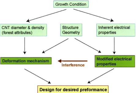
The objective of the thesis, summarized in Figure 1-3, is to correlate inherent CNT prop-erties to ultimate mechanical and electrical propprop-erties, and thereby linking the fabrication methods directly to the performance metrics by understanding the underlying mechanisms. The approach of the thesis is to characterize CNT structures on macro level and correlating them to the inherent properties of CNTs to get fundamental understanding. The thesis further investigates effect of geometry, and external modifications on CNT probe performance such as metal deposition onto the probes.
The organization of the thesis is as follows:
Chapter 2 discusses CNT growth techniques used in the thesis, their main differences and the resulting CNT properties in terms of their diameter, number of walls and density. It presents the fabrication method used for CNT probes and discusses the growth mechanism causing vertical growth, which is the main enabler of the column manufacturing. Chapter 3 presents the mechanical characterization of columns made of vertically aligned carbon nanotubes (VA-CNTs). Column grown with the three methods described in Chapter 2 are tested and compared in terms of their mechanical properties. It also presents deformation models and design guidelines for probe fabrication. Chapter 4 presents a transfer printing technique onto conductive substrate to achieve mechanical adhesion as well as electrical connection to the base substrate, which also in densification and stiffening of the CNT structures. Mechanical and electrical characteristics of transferred probes are presented. Chapter 5 presents metal film formation on CNT structures, metal-CNT hybrid electromechanical probes, their performance
Growth Condition
CNT diameter & density Structure Inherent electrical (forest attributes) Geometry properties
Interference
Design for desired preformance
Figure 1-3: Interdependancies of physical properties for structures made of carbon nanotubes.
and failure mechanisms. Chapter 6 presents another application of the growth methods and techniques used in this thesis, namely nano-art. SEM images of CNT structures after various processes such as sputter etching, focused ion beam milling, reactive ion etching, controlled buckling and electroless metal deposition is presented without any post processing. Chapter
7 summarizes important results and conclusions presented in previous chapters, fundamental contributions of this thesis and presents recommendations for future work.
Fundamental contributions of this work are:
" Methodology for mechanical characterization of VA-CNT structures (Chapter 3).
" Identification of a buckling based deformation mechanism for compressed CNT structures (Chapter 3).
" Demonstration of stiffness tuning of a CNT structure by controlled compression and buckle formation (Chapter 3).
" Demonstration of stiffness tuning by controlling gas composition during growth (Chapter 3).
" Investigation of the relationship between CNT growth method, resulting CNT structures, and macro-scale mechanical behavior (Chapter 3).
" Transfer printing technique to simultaneously transfer, densify and electrically connect CNT structures onto metal substrates (Chapter 4).
" Methodology for characterizing electrical properties of VA-CNT structures (Chapter 4).
" Metal formation on CNT structures for increased electrical conduction (Chapter 5).
" Metal-CNT hybrid electrical probe design where VA-CNTs act as elastic springs and metal coating serves for improved electrical conduction (Chapter 5).
" Demonstration of first fully functional electromechanical probes made fully of CNTs (Chapter 5).
Chapter 2
Carbon Nanotube Growth Methods
and Column Manufacturing
This chapter describes and discusses CNT growth techniques employed in this thesis.
2.1
CNT Growth Techniques
Among various CNT growth techniques including arch discharge and laser ablation [2], chemical vapor deposition (CVD) technique is the most suitable method for scalable industrial applica-tions where large number of CNT assemblies having micro to macro lengths is desirable. CVD techniques under the right conditions usually yield vertically aligned CNTs without external alignment efforts such as applied electric field during growth.
CVD growth technique can be divided into two main categories, namely fixed catalyst CVD and floating catalyst CVD. In the fixed catalyst CVD technique a thin film of catalyst layer [9, 10, 11, 12, 13], typically a transition metal, is deposited onto a support or buffer layer such as
A1203. Both layers can be successively deposited with various techniques including evaporation
or sputtering onto the growth substrate, typically silicon. In this method the carbon source is typically a hydrocarbon gas carried with an inert gas onto the growth substrate. The growth is typically conducted in a tube furnace heated up to 700 - 800*C range.
In the floating catalyst CVD technique, the catalyst particles are introduced in the gas phase instead of being deposited onto the growth substrate prior to the growth [14, 15, 16, 17,
80 E ---
---E
CVD a) 4 0 --- -- --- ---CU 20 -- - --- - --VD)
0
1 10 100 1000 10000CNT film height [ptm]
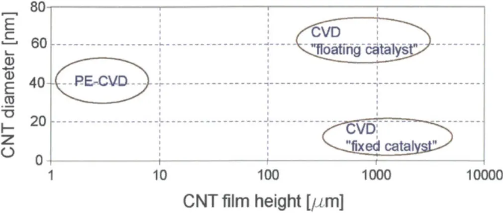
Figure 2-1: Comparison of growth techniques yielding VA-CNT films. For viable industrial applications, upper right corner is most desirable.
18, 19, 20, 21, 22, 23]. The carbon source is evaporated from the same solution containing the catalyst particles and carried along with the catalyst particles onto the growth surface, which is typically an oxide film. The growth is again conducted in a furnace at high temperature.
An additional variation of the CVD growth technique is the plasma enhanced CVD (PE-CVD) method, where growth is accomplished in a plasma environment [24, 25, 26, 27, 28, 29, 30]. Even though this technique yields very well aligned (due to the electric field) and large diameter CNTs, the film thickness is typically in the order of microns.
Figure 2-1 presents a comparison of scalable CVD growth techniques for micro/macro-scale applications. Due to their large film heights, fixed catalyst CVD and floating catalyst CVD methods are promising methods for scalable applications, and are explored throughout this thesis for the particular application in hand. The fixed catalyst method employed in this thesis is based on the method presented in [31], and the floating catalyst CVD growth is based on the method presented in [32].
2.2
Fixed Catalyst CVD Growth System
In this method, CNTs are grown from a catalyst layer of 1.2/10 nm Fe/Al203 film deposited by
e-beam evaporation on a silicon wafer and C2H4 gas serves as the carbon source. The furnace
5~t~ind~rd 9" Ii h0 fi m~r~
2" quartz tube
exhaust
_
Hydrocarbon gas
750C
Patterned catalyst layer
Figure 2-2: Schematics of the furnace used to grow vertically aligned carbon nanotube columns from "fixed catalyst".
Time(min.) Gas Flow Temp ('C)
0-10 400 sccm Ar 0
10-25 400 sccm Ar 0-750 (ramp)
25-35 400 sccm Ar 750
35-40 400 sccm H2,150 sccm Ar 750
40+growth time 400 sccm H2,150 seem Ar,100 sccm C2H4 750
-30min 400 sccm Ar furnace off
Table 2.1: Process condition for the growth with Argon flush.
growth is performed in a quartz tube furnace (Lindberg) at atmospheric pressure. The furnace is ramped to the growth temperature of 750 'C under 400 sccm Ar; then 400/150 sccm H2/Ar
is introduced for 5 minute, then 100/400/150 sccm C2H4/H2/Ar is maintained for the typical
growth period of 15 minutes. The details of the growth sequence is listed in Table 2.1.
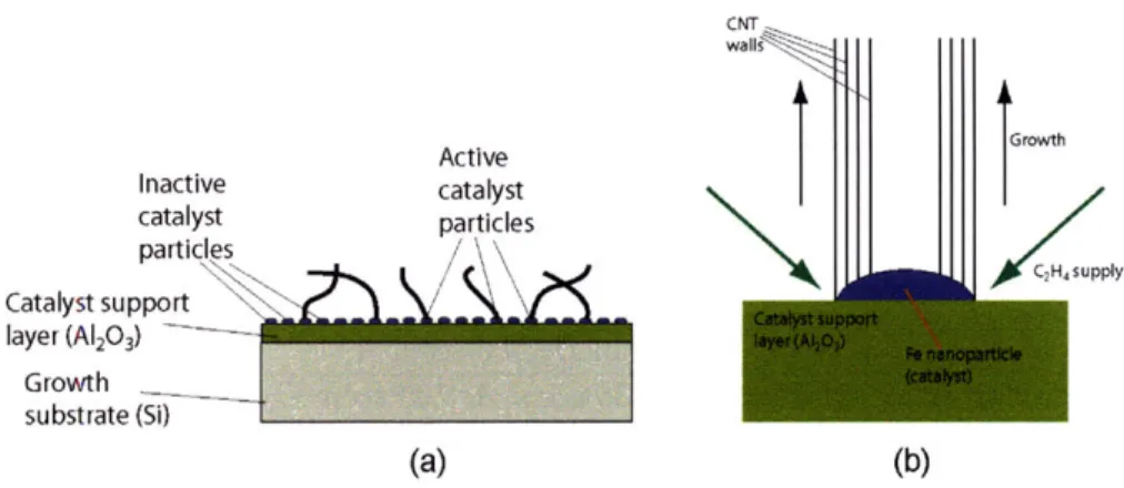
The fixed catalyst growth technique used here yields base growth, where the catalyst particle remains on the growth substrate and addition of carbon results in lengthening of the CNTs attached to the catalyst particle. Figure 2-3 demonstrates the base growth mechanism. It should be emphasized that not all of the catalyst particles yield a CNT. In fact, only a small fraction of them yield CNTs. The catalyst particle formation during the ramp time and subsequent activity has direct consequences on the CNT diameter and areal density of CNTs. It was recently demonstrated that introduction of hydrogen into the furnace during certain periods of growth has significant effect on catalyst activity [33]. Growth conditions of another variation of the fixed catalyst recipe where hydrogen is supplied during the ramp time as well (instead
Time(min.) Gas Flow Temp (0C)
0-10 100 sccm He 0
10-20 100 sccm He, 400 sccm H2 0
20-30 100 sccm He, 400 scem H2 0-750 (ramp)
30-40 100 sccm He, 400 sccm H2 750
40+growth time 100 sccm He, 400 sccm H2,100 sccm C2H4 750
~30min 100 sccm He furnace off
Table 2.2: Process condition for the growth with Hydrogen flush..
Active Inactive catalyst catalyst particles particles Catalyst support layer (A1203) Growth substrate (Si) (a) cur walls Growth 1 I . C2H upply (b)
Figure 2-3: Initial stages of vertical growth with base growth. (a) Sketch depicting random initial growth direction and inactive catalyst aprticles which don't yield CNTs. (b) Schematics of base growth.
of only 5 minutes prior to growth) is summarized in Table 2.2.
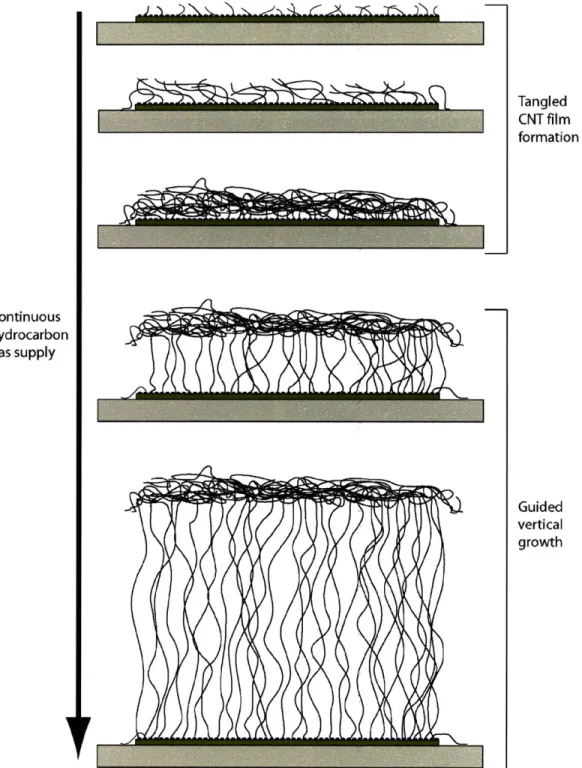
Figure 2-4 presents the initial stages of the CNT growth. The catalyst particles which don't yield CNTs can be clearly seen in Figure 2-4 (d). It is also worthwhile to note that the CNTs are initially not aligned and grow in all directions forming CNT clusters. The growth then continuous with the base growth mechanism. The formation of aligned CNT film is depicted in Figure 2-5. First, CNTs grow in all directions forming clusters. As the CNTs forming those clusters get longer and longer with the addition of new carbon atoms at the bottom where the reaction is catalyzed, the clustered layer gets lifted, resulting in guided growth of the CNTs. Basically, after a certain point, the CNTs have no where else to go other than growing upwards.
(b)
(c) (a)
Figure 2-4: Initial stages of growth with the base growth mechanism obtained with the fixed catalyst CVD method. (a) Circilar pattern. (b) Close-up image of a corner of transition between patterned layer and the support layer where no CNT growth occurs. Empty spots, due to inactive catalyst particles, can be seen. (c, d) Close up images of the empty spots showing the inactive catalyst particles and tangled CNT film formation from the neighbouring catalyst particles.
.. . ... ....
Continuous hydrocarbon gas supply Tangled CNT film formation Guided vertical growth
Figure 2-5: Sketch demonstrating vertical growth of CNTs and formation of forests.
-Standard 2" tube furnace
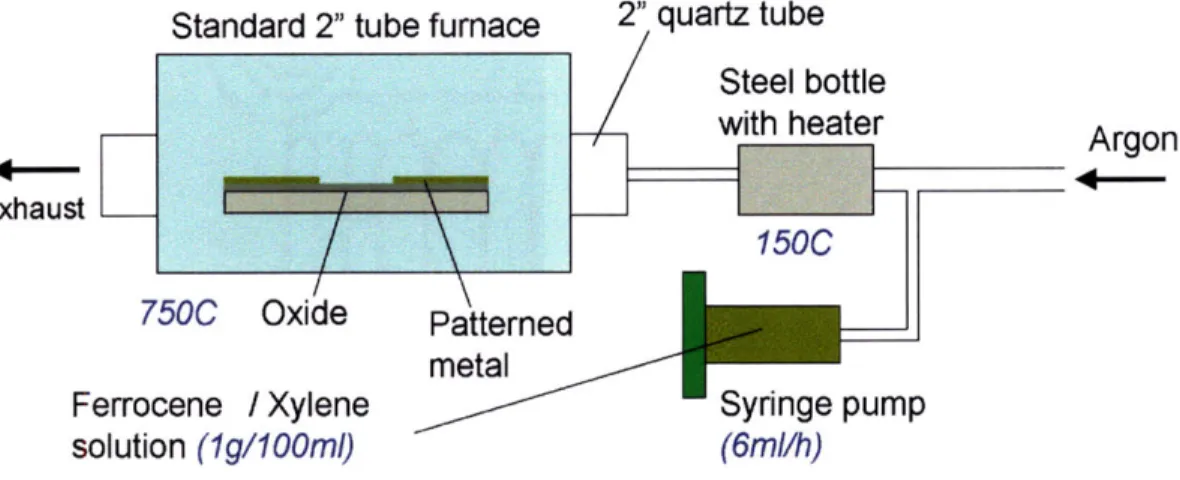
750C
Oxide
Ferrocene / Xylene
solution (Ig/100ml)
Patterned
metal
2" quartz tube
Steel bottle
v_Syringe pump
(6ml/h)
Figure 2-6: Schematics of the furnace used to grow vertically alligned carbon nanotube films from floating catalyst.
Ferrocene/Xylene solution lg/lOOml Syringe pump rate 6ml/h
Steel bottle temperature 1500C
Tube furnace temperature 750*C
Table 2.3: Process conditions for CVD growth with floating catalyst.
2.3
Floating catalyst CVD Growth System
The furnace schematics used for CNT growth with the floating catalyst method is shown in Figure 2-6. The carbon source (xylene) and the catalyst particles (Ferrocene-Fe(C5H5)2) are
contained in a solution and pumped through a syringe pump into a heated steel bottle where they evaporate and get carried into the furnace with Argon gas as carrier gas. Important process parameters are listed in Table 2.3.
A significant difference between the floating catalyst and fixed catalyst method is that during the floating catalyst CVD growth the catalyst particles constantly rain onto the CNTs and the catalyst particles can be found throughout the length of a CNT. Figure 2-7a shows a close up SEM image of the CNTs grown with this technique. Figure 2-7 is an SEM image taken in back-scattered mode showing catalyst particles along the length of the CNTs. CNT films grown with the floating catalyst grow in a similar fashion vertically upward and yield aligned CNTs.
exhaust_
rI
Argon
(a)
(b)
Figure 2-7: Close-up images of a column side wall gorwn with floating catalyst CVD. (a) CNT diameter measurements in SEM. (b) SEM image taken with back scattered electrons showing the bright iron nanoparticles acting as catalyst during the growth.
2.4
Comparison of CVD Methods
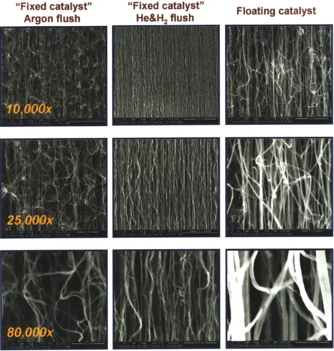
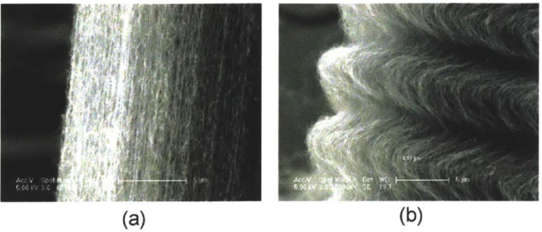
As discussed earlier, various CVD methods yield different inherent CNT film properties such as CNT diameter and CNT density. These are very important attributes of the CNT structures, and as will be shown in Chapter 3, they have very significant implications on the mechanical properties of CNT structures resulting from these methods. Close up SEM images of CNTs resulting from the CVD techniques employed in this thesis are shown in Figure 2-8. At a first glance, a significant density increase is noticed from the fixed catalyst growth without hydrogen to the fixed catalyst growth with hydrogen. This is attributed to the higher catalyst activity provided by the hydrogen gas. Another noticeable difference is the significant increase in CNT diameter from the fixed catalyst recipe to the floating catalyst recipe.
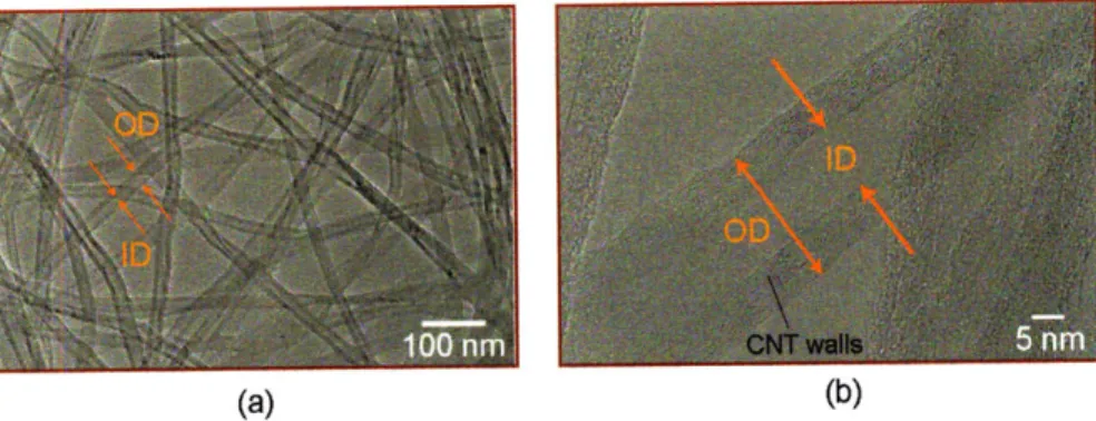
To get a better understanding of the CNT structures and obtain measurements of the inherent properties of CNTs, the films are analyzed with transmission electron microscope (TEM). Figure 2-9 shows TEM images of CNTs grown with fixed catalyst recipe (argon flush). First, the CNT film to be measured is dispersed in a isoprophanol bath and sonicated to separate CNTs from one another. Then the TEM grid is dipped into this solution with a tweezer and
"Fixed catalyst"
Argon flush
"Fixed catalyst"
He&H, flush
Floating catalyst
Figure 2-8: SEM images at increasing magnification of CNT column sidewalls grown with different CVD processes.
. ... . .. ... . ... . .... ... ..
(a) (b)
Figure 2-9: (a) Typical TEM image used to measure outer diameter and inner diamter of CNTs. (b) A close up image of a CNT. Both pictures correspond to CNTs grown with argon flush.
swept until some CNTs are captured onto the surfaces. After an image like 2-9 (a) is obtained, the outer and inner diameters of CNTs are measured with a microscopy software.
The density of CNT structures are calculated by measuring the mass of a continuous CNT film with a sensitive balance, and then dividing the mass by the volume of the CNT film. The volume fraction of the CNTs is calculated by dividing this density by the density of the graphite (2.2kg/m 3).The volume fraction of the CNTs can be also expressed as the area ratio of CNTs to the film area, as shown in Figure 2-10 which depicts 4 unit area containing one CNT and average CNT-CNT spacing a:
= ACNT _ (OD2 - ID2)ir (2.1)
V Atota 4a2
where Vf is the volume fraction, OD and ID are average outer and inner diameters measured by TEM, and a is average CNT-CNT spacing in the film. Using the measured values with TEM and the sensitive balance, average CNT-CNT spacing is calculated using equation 2.1. Table 2.4 summarizes TEM measurement results and related calculations.
2.5
Fabrication of CNT Columns
The ability to grow CNT films into desired shapes is very important for applications such as electromechanical probes. The nature of the growth mechanism discussed earlier should allow vertical growth from small areas of catalytic activity mainly due to the fact that CNT
ID OD
a
a
Figure 2-10: Unit GNT film area used to calculate average CNT-CNT spacing.
CNT growth recipe Fixed catalyst Fixed catalyst Floating catalyst Argon flush Hydrogen flush
Structural Density (kg/rn3) 8 15 200
Volume Fraction of CNTs 0.36 % 0.68 % 9.09 %
Structural Porosity 99.64 % 99.32 % 90.91 %
CNT Outer Diameter (nm) 25.8 8.1 89.9
CNT Inner Diameter (nm) 11.1 4.3 15.1
Average Number of Walls 21.7 5.6 110
Average CNT-CNT Spacing (nm) 342 74 260
CNT Areal Density (CNTs/cm2) 8.54x10⁸ 1.84x10¹⁰ 1.47x10⁹ Table 2.4: Comparison of resulting CNT properties from different recipes.
A
1) Clean Acetone-IPA-DI water
2) HMDS
3) Spin coat photoresist - AZ 5214E: 10s dispense @ 1rpm, then 30s 01500rpm
4) Pre bake : 90C 1min. (hot plate)
5) Exposure : 3s (hard pressure contact) 6) Post bake : 115C, 1min (hot plate) 7) Flood exposure : 2min (one exposure)
8) Develop: AZ400K(1:4), 90s
9) Wet transfer and hard rinse with water
Table 2.5: Image reveral process used to lift-off metal layer (Fe for fixed catalyst growth and Au for floaring catalyst growth) for desired pattern and column shape.
dimensions are much smaller than the pattern sizes. For the case of fixed catalyst method, shape control is achieved by patterning the catalyst layer from which CNTs grow. Similarly, for the case of floating catalyst growth, the area of the oxide layer is controlled by patterning a metal layer deposited earlier onto the oxide surface.
For both growth techniques, patterning is achieved using the lift-of process summarized in Table 2.5 based on an image reversal photoresist. After the lithography step, the metal layer to be patterned (Fe/A1203 for fixed catalyst and Au for floating catalyst method) is deposited
onto the photoresist and then lifted off in acetone. It is worthwhile to mention that if the patterning of the Fe layer requires a dark field mask, the patterning of the the Au will require a bright field mask, or vice versa, for the same geometric patterns
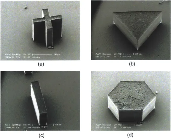
Figure 2-11 shows high pitch square and circular CNT columns grown with the fixed catalyst CVD method from patterned catalyst layer. This demonstrates the ability to control shape and pitch very accurately with this method. Similarly, shape control can be achieved with the floating catalyst CVD technique. Figures 2-12 and 2-13 show various examples.
This chapter provided discussions and details of CVD recipes employed in this thesis, namely fixed catalyst CVD, fixed catalyst CVD with hydrogen preconditioning of the catalyst layer, and floating catalyst CVD. Characteristics of the CNT structures, such as CNT diameter, CNT aerial density, and structural porosity, resulting from each growth technique were dis-cussed. This chapter also presented techniques to fabricate CNT columns with desired shapes by lithography techniques. The implications of the inherent properties of the CNT structures on the mechanical properties will be discussed in the next chapter.
(b)
(c)
(d) 7" -T IV. TI -L Lj-j,.,L L -L ar I -IF 1- L -1-Li IF T &'A I-ir IF (g) (h)Figure 2-11: CNT columns grown with fixed catalyst CVD method (hydrogen flush). Pitch, shape and height of the clumns can be easily controlled by patterning and by growth time respectively.
(a) (b)
Figure 2-12: Columns grown with floating catalyst CVD method.
(a)
(b)
(c)
(d)
Figure 2-13: Columns of diferent shapes grown with foating catalyst CVD method.
---Chapter 3
Mechanical Characterization of
Vertically Aligned Carbon Nanotube
Structures
This chapter presents a comprehensive study of the mechanical properties of VA-CNT struc-tures. CNT structures grown using the growth techniques discussed in Chapter 2 are charac-terized and resulting mechanical properties are compared. Deformation models to explain the mechanical behavior of CNT structures are discussed.
3.1
Experimental Setup and Testing Issues
Mechanical characterization of CNT structures is performed with a CETR Micro Tribometer (www.cetr.com) as well as in situ SEM with a probe inserted through a feed-through in the SEM chamber (www.omniprobe.com). The tribometer, which allows simultaneous measurement of applied force, displacement and time, is used for detailed testing and characterization whereas in-situ SEM probe is used to observe the CNT structures during compression, record videos and to get insight into the deformation mechanism.
(b) (c)
Figure 3-1: (a) Schematics of the experimental setup. As the punch, a 1.6 mm diameter brass rod is used. (b) Photograph of the tribometer used for mechanical characterization. (c) In-situ monitoring of CNT columns during compression with 2 perpendicular cameras. (courtesy of FormFactor, Inc.)
3.1.1 Tribometer
The experimental setup is shown in Figure 3-1, where CNT columns are compressed parallel to the CNT alignment direction. In all of the tests, the displacement is imposed at a constant rate of 10p/s and force is measured using a load sensor suited to the stiffness of the structure under the test. For softer CNT structures, as is the case with the columns resulting from the fixed catalyst CVD growth, a load sensor with a maximum range of 50g and a resolution of 50mg (0.5mN) is used, whereas for harder CNT structures resulting from the floating catalyst CVD growth, a 500g load sensor with a resolution of 0.5g (5mN) is used.
Force and displacement recorded by tribometer
F~Upunch
Camera for CNT column alignment substrate Camera for alignment (a)d fre
Figure 3-2: Components of the tribometer: The load sensor attached to the deformation stage which moves vertically through a leadscrew assembly. (courtesy of FormFactor, Inc.)
As both load sensors used are cantilever based detectors (strain gauges), it is important to take the stiffness of the load sensor into account when calculating the stiffness of the structure under test. This becomes especially very important when the stiffness of the structure under test is comparable to the stiffness of the sensor, which is the case for the tests performed with the 50g sensor. Since the structure and the load sensor act as springs in series, the stiffness of a CNT column, kc, can be calculated as:
ke= kskm (3.1)
ks - km
where ks and km are the stiffness of the load sensor and the measured stiffness respectively. Another important issue is the backlash in the leadscrew moving the deformation stage in the tribometer assembly, shown in Figure 3-2. The backlash is particularly important when one needs to perform cyclic testing. An example case is illustrated in Figure 3-3 for a leadscrew with a backlash of 1pm. If the experiment is adjusted such that at z = 0 the punch and sample are in contact, at the end of the first cycle, the sample is already compressed 10pm, and the force reading is positive. This is misleading and shows as if the sample is pushing back, or getting longer or stronger, which is in fact an artifact of the backlash. If the imposed deformation is 10pm or less, the deformation stage would not move at all. It is also important to note that the amount of backlash might vary along the length of the leadscrew. For the
Start experiment at
z=0 after taking
backlash by going
down for a while Take backlash Take backlash
-- 10pm 10pm
30pm
20pm 20pm 20pm 20pm
Take backlash Take backlash
10pm 10pm
Figure 3-3: Sketch depicting the backlash issue for 1Opm backlash, which makes it impossible to characterize columns at deformations near or smaller than 10pIm.
purposes of the current characterization work, this backlash didn't pose significant problem as all the deformations imposed during testing are larger than 50pm and backlash was around
5pm for the section of the leadscrew used during the experiments.
3.1.2 In-Situ SEM Compression
The in-situ compression tests are performed with a FEI dual beam system with an integrated OmniProbe. The particular model used is an earlier version and has manual controls. The in-situ probe doesn't have force or displacement sending capabilities and it was used to observe CNT structures deform during compression and gain insight into the deformation mechanism. The probe used to compress CNT structures is shown in Figure 3-4.
An important issue is the lateral stiffness of the probe for the experiments performed, as will be discussed in later sections of this chapter. The system used for in-situ SEM characterization has a long probe reaching from the tip of the probe assembly to the top surface of the CNT column. For the tests performed, it is very critical that the probe contacts the top surface of the CNT column perfectly parallel, as well as it is very rigid in lateral directions. As the probe assembly is mounted through a feed-through on the SEM chamber, attention needs to be paid so that the sample holder and the probe are perpendicular. If this is not the case, the effect of lateral compliance becomes more prominent. In the case of tribometer, lateral stiffness is not an issue.
(a) (b)
In-situ SEM Probe assembly
Probe guide Probe tip
Electron detector Pole-piece Sample holder
(c)
Figure 3-4: (a,c) Components probe inside the SEM chamber (courtesy of FormFactor, Inc.)
of the in-situ SEM probing system. (b) SEM image of the used to compress CNT structures for in-situ characterization.