Publisher’s version / Version de l'éditeur:
Vous avez des questions? Nous pouvons vous aider. Pour communiquer directement avec un auteur, consultez la première page de la revue dans laquelle son article a été publié afin de trouver ses coordonnées. Si vous n’arrivez pas à les repérer, communiquez avec nous à PublicationsArchive-ArchivesPublications@nrc-cnrc.gc.ca.
Questions? Contact the NRC Publications Archive team at
PublicationsArchive-ArchivesPublications@nrc-cnrc.gc.ca. If you wish to email the authors directly, please see the first page of the publication for their contact information.
https://publications-cnrc.canada.ca/fra/droits
L’accès à ce site Web et l’utilisation de son contenu sont assujettis aux conditions présentées dans le site LISEZ CES CONDITIONS ATTENTIVEMENT AVANT D’UTILISER CE SITE WEB.
Laboratory Technical Report (National Research Council of Canada. Institute for
Aerospace Research. Structures and Materials Performance Laboratory); no.
LTR-SMPL-2004-0175, 2004-08-17
READ THESE TERMS AND CONDITIONS CAREFULLY BEFORE USING THIS WEBSITE.
https://nrc-publications.canada.ca/eng/copyright
NRC Publications Archive Record / Notice des Archives des publications du CNRC :
https://nrc-publications.canada.ca/eng/view/object/?id=2ba09001-874b-40ca-bc6d-e012e10ec31a https://publications-cnrc.canada.ca/fra/voir/objet/?id=2ba09001-874b-40ca-bc6d-e012e10ec31a
NRC Publications Archive
Archives des publications du CNRC
For the publisher’s version, please access the DOI link below./ Pour consulter la version de l’éditeur, utilisez le lien DOI ci-dessous.
https://doi.org/10.4224/23000207
Access and use of this website and the material on it are subject to the Terms and Conditions set forth at
Anti- and de-icing methods for rotorcraft applications: a critical review
Patnaik, P.C.; Sarda, K.; Leung, W.; Carignan, S.; Oleskiw, M.
1+1
National Research Consell national Council Canada de recherches Canada Institute for lnstitut deAerospace Research recherche aerospatiale
Unclassified Unlimited
Anti-
&
De-Icing Methods tor Rotorcraft
Applications: A Critical Review
LTR-SMPL-2004-0175
P.C. Patnaik, K. Sarda, W. Leung, S. Carignan and M. Oleskiw
August 2004
INSTITUTE FOR
AEROSPACE RESEARCH
Pages: 59 Tables: 19 Figures: 27For:
Pour:
Reference:
Reference:
REPORT
RAPPORT
STRUCTURES, MATERIALS AND
PROPULSION LABORATORY
LABORA TO IRE DES
STRUCTURES, DESMA TERIAUX
ET DE PROPULSION
INSTITUT DE RECHERCHE
AEROSP ATIALE
Report No.: LTR-SMPL-2004-0175 Date: 17 August 2004 Classification: Unclassified Distribution: UnlimitedLTR-SMPL-2004-0175
Anti-
&
De-Icing Methods for Rotorcraft Applications:
A Critical Review
Submitted by:
Presente par:
J.P.
Komorowski
Director!Dirccteur
Approved by:
Approuve par:
D.L.
Simpson
Director GeneraVDirecteur general
TIUS REPORT MAY NOT BE PUBLISHED WHOLLY OR IN PART WITHOUT THE WRIITEN CONSENT OF THE INSTITUTE FOR AEROSPACE RESEARCH.
Author(s):
Auteur(s):
P.C. Patnaik
K. Sarda
W.
LeungS. Carignan
M. Oleskiw
CE RAPPORT NE DOlT PAS ETRE REPRODUIT, NI EN
ENTlER NI EN PARTIE, SANS UNE AUTORISATION ECRITE DE L'INSTITUT DE RECHERCHE AEROSPATIALE.
Anti-
&
De-Icing Methods for Rotorcraft Applications: A Critical Review
Prakash C. Patnaik *
Karan Sarda *
Wayne Leung*
Stephan Carignan**
Myron Oleskiw ***
* Structures, Materials
&Propulsion Laboratory
**Flight Research Laboratory,*** Aerodynamics Laboratory
IAR-NRC, Ottawa
Executive Summary
In-flight and ground icing has historically posed a significant problem for all types of aircraft, and has been determined to be the cause of numerous accidents. Canadian airspace is especially hazardous as air temperatures are typically sub-zero, leading to ripe conditions for the onset of icing. Ice accretion on the leading edge and other areas of wings, fuselage, windows, engine inlets, and sensors degrade the aerodynamic form of the aircraft, and results in decreased lift and a higher stall velocity. Multiple solutions to this problem have been developed and applied to fixed-wing and, to a lesser extent, rotary aircraft. Most of these applications have shown promise and some have already seen limited service time. However, all current applications have considerable disadvantages, specifically in terms of weight and power requirements.
Rotorcraft are known to be particularly sensitive to in-flight icing due to the large effective distance the rotor blades travel compared to the effective distance that any component of a fixed-wing aircraft travels. The lift generated by the rotor blades is extremely sensitive to the effective shape of the blade itself; therefore, it is imperative that ice is either prevented from forming, or effectively removed once formed.
The majority of today's civil and military helicopters certified to fly in icing conditions are equipped with electro-thermal ice protection systems. Due to their proven record of reliability, durability and effectiveness versus the complete spectrum of other de-icing technologies developed, electro-thermal de-icing remains the favored solution after decades of research and development. However, due to the weight and considerable power consumption demands of an electro-thermal system, alternate anti- and de-icing methods have been intensely studied. This paper summarizes the numerous anti-/de-icing methods that have been studied and/or applied to rotorcraft to replace the electro-thermal systems and explores the feasibility of using shape memory alloy actuated systems as a more efficient means of rotorcraft de-icing.
Table of Contents
Executive Summary ... ... 1 Table of Contents ... ... ... ... ... 2 List of Figures ...3
List of Tables ... 4 1.0 Introduction ... ... ... ... ... 5 2.0 Electrothermal de-icing ... ... ... ... 113.0 Pneumatic rotor de-icing ... ... 18
3
.I
Small tube pneumatics (STP) ... 234.0 Pneumatic impulse ice protection (piip) ... 24
5.0 Fluid Anti-icing ... 27
6.0
Electro-vibratory de-icing ...33
7.0 Electro impulse de-icing systems (EIDI) ... 35
8.0
Coatings ... 418.1 Investigation of Novel Ice Release Coatings ... 41
8.2 Active de-icing coating for airfoils ... 46
9.0 Shape Memory Alloys ... 50
9.1 Passively-Powered SMA Design: ... 52
9.2 Actively-Powered SMA Design: ... ... ... 54
10.0 Summary ... ... ... .... ... 57
Figu
... 1
... 2
... 3
... 4
... 5
.. 11.. 18
.. 23
.. 24
.. 27
... 33
... 35
... 41
... 41
... 46
.... 50
.... 52
.... 54
.... 57
List of Figures
Figure
1.Typical ice formations : a) Rime ice b) Glaze or clear ice c) Mixed ice d) Icing
type frequency of occurrence .... ... ... 7
Figure 2. Schematic setup of a rotorcraft electrothermal de-icing system ... 12
Figure 3. Cross sections of three typical electrothermal heater elements ... ... 13
Figure 4. Span wise and chordwise heater cell installation arrangement. ... 15
Figure 5. Pneumatic de-icing system schematic .... ... ... 18
Figure 6. Pneumatic boot leading edge installation . ... ... ... ... ... 20
Figure 7. a) Spanwise and chord wise boot orientations b) Proposed rotorcraft boot.. .... 20
Figure 8. PIIP schematic .. ... ... ... ... ... ... 24
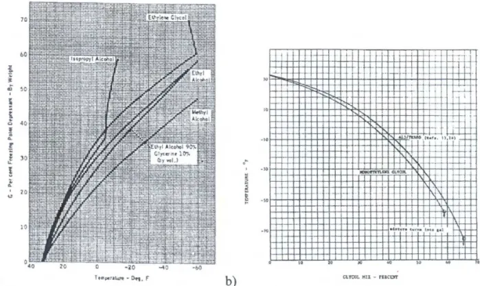
Figure 9. Common ice phobic fluid characteristic curves: Freezing temperature vs .
percent weight FPD ... ... 28
Figure 10. Fluid ice protection system schematic for rotorcraft .. ... .. .... ... 29
Figure 11. a)A typical view of a porous panel b) Cross section of a porous panel ... 30
Figure 12. The cross section of a conventional rotorcraft fluid ice protection system: Note
the forward and aft grooves milled into the nose block ... 30
Figure 13 . Possible shaker mount positions on rotor. ... ... ... 34
Figure 14. Coil magnetic fields and resulting eddy currents produced in skin due to coil
discharge ... ... ... 35
Figure 15. Electro-impulse coils mounted on either airfoil skin or internal supporting
structure ... ... ... ... ... 36
Figure 16.
AnEIDI system for a fixed wing aircraft ... ... ... 37
Figure 17. A basic EIDI circuit.. ... ... .... .. ... .... ... 38
Figure 18. Electrolytic gas generated by applied voltage . ... ... .. 47
Figure 19. Schematic of grid and electrodes arrangement. ... ... .... 48
Figure 20. Bulk current travels within the ice body between the cathode and anode.
Surface current travels along the ice/substrate interface between the two
electrodes . ... ... ... ... 48
Figure 21. Shear testing results: decreasing interfacial shear strength with increasing
applied voltage ... ... ... ... ... 49
Figure 22. Thermal cycle required for martensite to austenite phase change for NiTi
SMA ... ... ... ... ... ... ... . 5 1
Figure 23. SMA ice debonding mechanism .... ... 52
Figure 24. Passively-powered SMA concept: A thin NiTi sheet is placed over leading
edge and allowed to thermally deform ... ... ... ... 52
Figure 25. SMA passively-powered operation principle . ... ... . 53
Figure 26. Temperature vs. Time curves: Temperature at the ice interface recorded with
time for 5 different samples frozen at different ambient temperatures. Note
lower the ambient temperature, more pronounced temperature ranges
experienced . ... ... ... ... 53
List of Tables
Table 1. Adhesive shear strength of ice,
t a ... . ... .. ... ... ... .... .. ... ... ... .. .. .. .... . ... .. .... . ... . ....9
Table 2. Weight breakdown of electrothermal systems: ... ... 16
Table 3. Production helicopters certified for icing condition flight.. ... 17
Table 4. Weight breakdown of pneumatic de-icing systems ... 22
Table 5. Weight, power, and size specifications of a PIIP system ... 26
Table 6. Fluid weight calculation ... 31
Table 7. Anti-icing system weight breakdown ... 31
Table 8. Weight and power requirements ofEIDI systems ... 39
Table 9. Shear adhesion of various types of ice to uncoated brass rods ... 42
Table 10. Comparison of torque and tensile rod shear techniques .. ... ... 43
Table 11. Torque adhesion of various types of ice on an alkyd coating at -20°C ... 43
Table 12. Torque adhesion of ice on various coatings and coating additives ... 43
Table 13. Impact test on ice produced incrementally .... ... 44
Table 14. Impact test on ice produced with sprayed water. ... ... 44
Table 15. Composition of tested resins and additives .. ... 44
Table 16. Torque adhesion values for ice release coatings ... ... 45
Table 17. Results of ice accretion tests ... ... ... 45
Table 18. Effect of accelerated weathering on ice release properties ... ... 46
Table 19. Weight, power required, aerodynamic penalty, and run back potential summary
of several de-icing systems ... ... ... ... 57
4
The ex is typic Syste bond1... 9 .... 16
.... 17
.... 22 .... 26.... 31
.... 31
.... 39
.... 42 ... 43 ... 43 ... 43 ... 44... 44
... 44... 45
... 45
... 46
1111ary... 57
1.0 Introduction
Aircraft icing has been a problem that has plagued aviators since the dawn of aviation. Frigid atmospheric temperatures as aircraft pass through clouds produce conditions favorable to the onset of ice formation on the fuselage, wings or, in the case of rotorcraft, the rotor blades. As the formation of ice alters the airfoil shape, aircraft performance degrades; lift is lost, drag increases and stall speed increases. Asymmetrical flight characteristics experienced in rotorcraft due to the varying ice formations accumulated on different blades induce severe vibrations which could potentially damage the gearbox, drive train and airframe or result in a loss of flight stability. In order to provide full icing capabilities, protection must be provided to engine intakes, windscreens, aerials, and wings. However, it is rotor blades that present the greatest design challenge .
Protection systems can be divided into two categories: anti-icing systems which prevent any icing formation, or de-icing systems which act to de-bond existing ice formations . To date, the electro-thermal anti-/de-icing systems remain the favored solution, and are employed on most military and civilian aircraft currently certified to fly in icing conditions. The excessively high-energy requirements of electro-thermal protection systems have lead researchers to develop economical and practical de-icing systems. In the search for new helicopter de-icing systems, the following goals have been established:
a) Low power input b) Low gross weight
c) Sufficient sand and erosion resistance properties d) Aerodynamically non-intrusive design, and e) Cost efficiency
The mechanical and thermal systems currently employed are not economically efficient, while existing chemical systems are ineffective, as films exhibit poor weathering capabilities and typically shear off once the aircraft is airborne.
Systems can be designed intrinsically into the airfoil to eliminate aerodynamic effects, or can be bonded to existing airfoils as retrofit applications. In designing a helicopter ice protection system, the following issues must to be taken into account:
a) Chord-wise and span-wise extent of ice formation b) Rate at which ice accretes on the blades
c) Type of ice which forms
d) Degree of aerodynamic degradation e) Airfoil shape and structure
f) Electric power capacity
g) Transmission of power from fixed base to rotating blades h) Ice detection and warning systems
i) Power systems and pilot interfaces
Prior to the design phase, a good knowledge base on the mechanics of adhesion characteristics of the ice/substrate interface bond must be established either by testing or by literature study. Without this knowledge, realistic design requirements will not be known, possibly leading to another impractical, and unsuccessful strategy.
In the event of icing the greatest threat to rotorcraft flight safety is the degradation of aerodynamic flows. Water droplets exist in the atmosphere in a super-cooled liquid state at temperatures as low as -40°C and are formed by condensation of water vapor onto airborne particles such as dust and pollutants. The droplets remain in this super-cooled liquid state until an event such as a passing of an aircraft disturbs this equilibrium state allowing ice crystals to nucleate on the aircraft surface [I ,2). Ice formation would increase the weight and induce drag causing the rotorcraft to experience a torque rise and loss of lift, ultimately resulting m performance losses. Further problems upon the onset of icing are associated with shedding. If ice shedding is asymmetrical, large strains concentrate on the gearbox, producing dangerous vibrations and control difficulties. Asymmetrical shedding is a severe problem due to the statistical variation of adhesive strength along the ice/substrate bond, and possible partial failure of de-icing system components leave some blades able to de-ice and others not.
Ice can form in diverse densities and configurations and, as a result, the mechanical properties vary considerably. It is therefore necessary to determine and differentiate between these types of ice. Several types of ice produced and observed in icing tests are discussed below [ 1 ,3).
a) Wind tunnel ice: Substrate is cooled below the freezing point of water; water is then sprayed onto the substrate. Size and droplet momentum can be controlled by this approach.
b) Natural ice: Ice formation on a substrate is exposed to the atmosphere under natural occurring conditions.
6
Fig
perties -pes of
.s then >y this
natural
c) Rime ice - Figure la, le: A non-homogenous phase consisting of powdery shaped particles; Super-cooled water droplets freeze immediately upon impact, trapping air beneath the surface which attributes to the distinct white appearance. Normally, rime ice accretes onto the leading edge and acts as an extension to the leading edge. High surface roughness increases drag, resulting in early boundary layer separation promoting blade stall. Rime ice is the most frequently reported ice type [21]. It is formed between temperature ranges between -40°C and -l5°C, p = 880 kg/m3.
Glazed ice - Figure I b, 1 e: A homogeneous transparent hard solid phase of ice. Causes significant drag increase and lift losses, as horn shapes grow if icing encounter is sufficiently long; Water flows along blade before freezing. Ice is formed between temperature ranges from -1 0°C to 0°C, p = 917 kg/m3 (no trapped air within body). Mixed ice - Figure lc : Glazed ice surrounded by finger-like shaped rime ice. Shapes will depend on ambient temperature, liquid water content (L WC), airspeed, altitude, etc. It forms between - 1
ooc
and -l5°C.Figure 1. Typical ice formations: a) Rime ice b) Glaze or clear ice c) Mixed ice d) Icing type frequency of occurrence. [21]
Water impingement rates theoretically dictate the location of ice formation, and therefore would likely predict that the outboard span of the rotor blade would accumulate more ice since it effectively travels further in moist air. However, centrifugal and aerodynamic forces acting on the rotating airfoil prevent any appreciable ice formation on the outboard region. Viscous kinetic effects near the blade tip dominate the thermodynamic heat balance, hence freezing of impinged water will not occur and the ice level will decrease at outward span locations [4]. However, at temperatures lower than -1 0°C ice can form along the entire leading edge of the main rotor. On average, cloud ice will form from the leading edge to 15% of the mean aerodynamic chord (MAC) on the top surface, and to 25% MAC on the lower surface [5].
Extensive research has been conducted on the mechanics of ice bodies, particularly on aircraft icing, with various experimental procedures and approaches adopted to measure the mechanical properties of ice. However, due to the variation of these procedures and the inherently stochastic nature of ice, this testing has led to a wide range of values for the adhesive strengths of ice. However, the data and knowledge gained from these individual tests are not at all wasted. By analyzing data trends, significant fundamental principles can be exposed. In the following text, important and noteworthy observations and facts about ice behavior with direct relevance to the rotor blade-icing problem are discussed.
Using replicas of ice surfaces from polymer and metal coatings, Bascom et al. found that the basal planes of ice crystals were oriented parallel to the shear surface, thereby exhibiting very weak shear characteristics when compared to high tensile strength for prismatic slip. This observation, strengthened by research conducted by Scavuzzo and Chu, has shown that the predominant approach in breaking the adhesive bond of ice is by using shear forces [ 1].
The adhesive shear strength of ice was found to increase linearly with decreasing substrate-interface temperature to a specific point. Scavuzzo and Chu discovered that this specific point was -3.9°C: below this temperature, shear strength varies slightly. However, a maximum shear strength (150 psi) is obtained at -7°C [1]. Jellinek, Stallbrass, and Price, however, found that the ice shear strength increases linearly with decreasing temperature to -l3°C, which they claim is the point where the adhesive strength of the ice/substrate bond becomes greater than the cohesive strength of ice. Other researchers also reported similar findings, claiming a range of temperatures where ice will fracture cohesively or at the ice/substrate interface. However, the point at which the adhesive strength of ice exceeds the crystalline strength of ice varies with each report.
mld .e it tthe 1etic 1ged :r, at On hord セ」イ。ヲエ@ mical 1astic f ice. l. By セエ・クエL@ to the tat the g very This 1at the )Strate-c point n shear that the n is the ohesive eratures Lt which , report.
Another researcher, Itagaki, claimed no change in shear strength at all with decreasing temperature [6]. ltagaki did claim that tensile strength increases with slower grown ice, however shear strength increases with faster grown ice [6]. Therefore the results from literature are very scattered due to the varying methods used to obtain these results.
Scavuzzo and Chu's research presented some other interesting conclusions on the adhesive shear strength, 'ta, of ice. They, along with Stallbrass and Price, found that 'ta was independent on the
substrate material, ambient temperature (not substrate-interface temperature), and ice thickness. Stallbrass and Price, claimed that ice would stick to Teflon-coated objects as strongly as it would to metal objects [6].
Several researchers, including Lynch and Ludwiczak, concluded that surface roughness plays an important role in ice adhesion. A rough surface, contaminated with scratches and other surface defects, will have a greater contact surface, and therefore a greater shear stress will be needed to de-bond the ice.
The observations of Scavuzzo and Chu regarding factors that are dependant and independent of the adhesive shear strength of ice are summarized in Table 1.
Table 1. Adhesive shear strength of ice, 'ta
Factors which affect
TaFactors which do not affect
Ta•
Surface roughness
•
Material substrate
•
Wind velocity
•
Rotation or non-rotation of
•
Droplet momentum
specunen
•
Ice/Substrate interface temperature
•
Ice thickness
•
Impact ice type (rime, glaze, etc)
•
Surface contamination (oil, rust,
fingerprints)
Researchers Miller & Bond [6] conducted rotor-icing studies specifically relating torque variations experienced by the rotor to various tunnel conditions. They concluded that torque, or the equivalent icing rate, rises linearly with time as a result of the various rotor and tunnel conditions listed below:
a) Cloud conditions, temperature, liquid water content (L WC), droplet size
Their accumulated ice profiles were found to be fully repeatable, as were the torque values until shedding. The radial extent of non-shed ice proved to give repeatable results. However, shed time, location and quantity of shedding did not.
In order to obtain a valid solution to the icing problem, the mechanics of ice-substrate bond and the expected adhesive tensile and shear strength values of the ice-substrate interface need to be determined. Also, the span-wise and chord-wise extent of icing as well as the shape and rate of growth must be accurately predicted. It would be beneficial to conduct specific in-house rotor icing experiments prior to de-icing system design. This will provide an essential first step to addressing the design requirements of a rotor de-icing system.
Amidst all the scatter of the literature results, trends show that the adhesive shear strength for glaze ice is significantly higher than rime ice, the former approaching magnitudes almost twice as large as the latter [6]. Crack propagation in rime ice is faster than in glaze ice due to the high density of pores. Rime ice will fail cohesively rather than purely at the ice substrate interface [1].
il :d :>e of :or to for
: as
igh l].2.0 Electro-thermal Ice Protection
The majority of the civil and military helicopters currently certified to fly in icing conditions are equipped with electro-thermal ice protection systems. Due to their proven record of reliability, durability and effectiveness compared to the complete spectrum of competing de-icing technologies developed, electro-thermal de-icing remains the favored solution after decades of research and development.
The principle of the electro-thermal systems is simple and can be categorized into either anti-icing or de-anti-icing classes. In the anti-anti-icing case, the heat is used to evaporate or prevent impingement of cloud water droplets onto the aircraft surface. The heat provided by the resistive elements maintains the surface temperatures to either evaporate the droplets upon contact, or only provide enough energy to prevent ice from freezing (known as "running wet" systems). Caution must be taken to design running wet systems, as the water may refreeze in critical locations. On the other hand, for de-icing electro-thermal systems, the heat provided is used to de-bond the formed ice caps from the surface by melting the ice at the substrate-ice interface, thereby allowing aerodynamic and centrifugal forces to sweep the ice away. Since electro-thermal
de-icing systems only realistically destroy the ice substrate interface bond and rely on centrifugal and aerodynamic forces to remove the bulk ice, it is evident that the ice thickness must be at a minimum value (roughly 0.3") [4) to have effective shedding.
The following equipment is required for a typical electro-thermal system:
l.
ii.
Ill.
lV.
v.
Power source - either an extraction of the aircrafts own electrical system or an auxiliary power unit
Power distribution system
Control system (manual or automatic) Resistive heaters
r
__
KYn..._IWY j_ _ _, IlMGセセM
...JFigure 2. Schematic set-up of a rotorcraft electro-thermal de-icing system. [7]
A schematic of the set-up for an electro-thermal de-icing system is shown in Figure 2. The heater mat assembly consists of resistive elements (mat, foil, or coil format) incorporated within layers of composite material, normally fiberglass/epoxy, plastic, rubber, or metal. The heaters are typically:
a) Woven or etch foil bonded onto a carrier b) A conductive composite material, or c) A sprayed metallic coating
The materials chosen for the heater blanket must be resistant to rain, hail, and insect strikes, must have good fatigue and thermal limits (cyclic expansion and contraction), and adequate stress-strain properties. A dielectric layer is sprayed onto both sides of the heater mats in order to insulate them from energy loss to the erosion shield and spar. A schematic of typical heater mat assemblies is given below in Figure 3.
eater ; are must tress-ler to rmat 0 012' n・ッーイ・セ・@ Outer Lllyer 0.003' Glass c.oth
セセセセセセセセf
セ@
0 001' Heat•ng Elements NACA Heater Construct•onIAat•mum 22 watts. sq n Bonded to surface 0 003' Glass Cloth 0 125' SynthetiC Rubber Inner Layer A um1num Sk1n . . _ , - 0 005' Sta1nless Steel ャゥセセセセjZiセBGjMェセセMML⦅@ 0 012' 1nsotat10n
ォlNセhセセセセセ[l@
0.003' R1bbon Heatert
0 012' nsutat•on uNNZセZZNNNNNャNNセセNNNNL⦅[N⦅L⦅Z^NNNN^NNj@ 0 025' Alum•num sセョ@Typical H11ter Conslrucbon ""'h Meta oセ・イウィッ・@ - 18-22 "'atts,sq •n
l amtnated to structure
r-
0 005' Staonless SteelZセZAZュZZZセZセZZュZZZ[ZZ[ZZセセ
ャZャN|NNZVセ⦅LNNNLGMBGMGNN⦅LN⦅NNNNNNLNNQNQNNNNNNLN⦅Nセ@
Z[セNセセセ[[Zセ[ZZZ@
セ[@
, ... "'
0 010' Epoxy ImpregnatedTyp1ca Heater Consuuct•on Glass Clath Molded as a Structural '-'ember·
16-20 watts/&q '"
Figure 3. Three typical cross sections of electro-thermal heater elements. [7]
Typically, there are two ways of installing electro-thermal de-icing systems. Flexible wrap-around heating mats can be installed directly onto the blade exterior with the use of adhesives as a retrofit application. Alternatively, the de-icing pads can be molded flush into the leading edge, with no aerodynamic losses. Rotorcraft de-icing systems are most likely constructed to employ composites rather than rubber boots due to high rotation speeds, which translate into higher loads per unit weight [7]. Electrical wiring for electro-thermal de-icing systems is not a significant design challenge within fixed wing aircraft as there is abundance of space inside the wing. However, the small blades of rotorcraft render wiring more difficult More significantly the power distribution from a stationary airframe to a rotating rotor, creates a challenge. Due to sand and rain erosion problems, electro-thermal de-icing systems are also retrofitted with an erosion shield mounted onto the leading edge. This erosion shield will inherently serve another purpose
by evening out the heat distribution and preventing cold spots [7]. Within a composite structure such as the one used for this system, it is important that the thermal expansion and contraction properties of all materials are relatively similar.
Tests have shown that most ice accretion occurs between 40-80% of the lifting surface's span, with the origin at the root At the inboard portion of the blade the rate of droplet impingement is low and towards the tip kinetic effects and centrifugal forces are high, therefore in these regions,
ice formation is at a relative minimum. This difference in the rate of ice impingement must be considered when identifying heater element location and power output.
A major design constraint is to minimize the electrical requirement of the overall system. For an efficient de-icing operation, a sufficient amount of heat energy must be efficiently supplied to the icing area. This constraint leads to the following design implications when designing an electro-thermal system [7]:
1. Applying heat to the entire blade is impractical- a power source larger than that
available from the aircraft's power source is needed. Hence the heater mats are cyclically heated between blades, and further cycled between chord-wise or span-wise locations of the blade.
ii. Since atmospheric cloud ice forms only on the leading edge of lifting surfaces to 15% mean aerodynamic chord (MAC) on the top surface, and 25% MAC on the lower surface [5], heater mats are only needed in this region. However, if heat is applied only in this region, a possibility exists of the runback water refreezing further down the chord of the blade, possibly on critical components.
111. The system can be made more efficient by applying high specific heat over a
shorter time as opposed to low specific heat over a longer time span. The high specific heat input reduces the convection losses from the exposed ice surface, conductive losses to the structure and to a lesser degree, compensates for the uncertainty caused by the large variation in the bonding strength of ice.
iv. Good insulation between the heater and the supporting structure is necessary to ensure that all heat is directed towards the ice.
v. A chord-wise gradient to heat input may be required to encourage uniform melting of the bond over the protected surface. This will produce clean shedding, and help to avoid runback.
Vl. Cycle off-time should be controlled to permit adequate ice accretion for the best shedding characteristics.
vii. Shedding symmetry: For a four bladed rotor, it is conventional to de-ice two opposing blades simultaneously. Unsymmetrical shedding will cause rotor unbalance, and potentially catastrophic vibrations.
Shedding zone power requirements are difficult to determine. Heat transfer rates, aerodynamic forces, and ice/substrate adhesive bonds are just some of the factors that affect the power
Fipr The , separ often ウ・セ@ to CDI
t be . For an :d to the electro-hat >pan-セウ@ to . the
a
igh ce, e yto dding, e best 10 r iynamic : powerrequirements. Element-on-times (EOT) must be carefully chosen in order to effectively and uniformly melt the ice. Because helicopter rotor blades have comparatively small chord-lengths, EOT typically approaches I second at relatively warm temperatures, while fixed-wing aircraft use EOTs of much larger magnitudes [7].
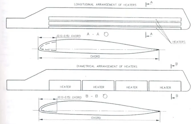
As previously mentioned, in order to mtmmtze power consumption at a given time and to increase efficiency, heater mats are arranged either span-wise or chord-wise on the airfoil. Typically, the heating elements are activated tip to root for the span-wise system, or stagnation point and outwards for the chord-wise systems. The design challenge of chord-wise sectioning is laying wire within the small rotor blade and would lead to a greater possibility of malfunction; however, this arrangement has proven to be more efficient [8]. Both arrangements are shown in Figure 4. Within the heating elements themselves power variations can be made by altering the resistance values or by varying the EOT to create a homogeneous ice melt distribution .
LONGITUDINAL ARRANC(MUH Of HlATERS
ll All rセ@
()IAM(TRICAL ARRANCEI.4ENT Of" HEATERS
,---'/ r---..
r - - - , \ IIE"AHRII
HfATFRセイセM
Mエャ ヲM Na M je MイセMMML
ャイMQMM
セセMlaMQᆪMNhM
MMNl
j@
-fd
<0_1_3_·-0 -ISJ_ C_H_OR_0_ 8_ -_ £J _ _o
--
MM
セ
Z@
CHORD _--
-Figure 4. Span-wise and chord-wise heater cell installation layout.
The electrical system, which can either run on the existing helicopter electrical source or a separate dedicated system, must be properly sized for the required electrical load. This constraint often results in a larger power requirement than the existing electrical system can allocate. A second large electrical system needs to be installed due to FAA redundancy requirements in order to ensure safe operation when icing conditions are encountered. For a mid-size helicopter, the
weight of an alternator alone is approximately 54 lbs. Due to this imposed restriction, major performance and cost penalties result [5].
ln a pre-determined sequence and EOT set by the controller, a power pulse activates each element when triggered by a mechanical or solid-state switching device located in the rotor head. Power is distributed from the rotor mast to the rotating blades via a slip ring system.
The controller may be either an automatically or manually controlled system. In the case of an automatically controlled system, element on time is based on the ambient air temperature, or the icing rate, while the element off time is based on the icing rate. For manually controlled systems, the pilot can input the ambient air temperature, and use his/her judgment to determine the icing severity. Manually controlled systems are not recommended for composite blades however, since overheating problems are more of a concern.
Table 2. Weight breakdown of electro-thermal systems: [5]
•
•
•
•
Blad« beaten (4 blades)
Coetrok
Sllpriag ucl セ@
Wlrtna
1'a.ll rotor 1ystaa
Ahem.atoc ud drM. No. I
AltcnuttDr uti drin, No. l
Advantages
Majority of aircraft certified to fly in icing conditions are fitted with electro-thermal systems, hence providing a large bank of knowledge in
maintenance, repair, operation, and design
Effective and reliable
Action time virtually unlimited Operating parameters are variable depending on atmospheric conditions
•
•
•
•
lllbu
7 1J lO 54 .M Total 16llb Disadvantages/LimitationsThree major problems arise from this type of de-icing system: weight, electric power, and aerodynamic performance degradation
Power consumption is very large, and in some cases even impractical. Electrical de-icing systems for rotor blades use up to 12 kW of power to achieve all weather flight capability [ 1].
Weight increases due to implementing electrical redundancy (2 alternators) according to FAA regulations (table 2). Melt water runback. The fluid has a potential to refreeze in critical zones, degrading flight characteristics. Heating the entire blade to compensate for runback problems is extremely power consuming, and thus impractical
Ljor .ent 'fis セ。ョ@ the ms, :ing nee is ing ) セ@ 2). s, ;ate :ical
•
Element burnout. No redundancy exists, hence ice shedding may be asymmetrical which induces detrimental flight characteristics for rotor craft•
Minimum ice thickness. Allowing the 0.3" ice build up induces moderate performance penalties. Tests on Bell 214ST, which has a 33" chord, 6-blade design experienced a 2.2% torque rise, and Bell412, with a 17" chord, 4-blade design experienced a 10% torque rise [5]•
ET systems give the highest cost per performance compared to any other de-icing system [5]Table 3. Production helicopters certified for icing condition flight. [5]
c;,_ Sysl.tm tセ@ l:Jtctrical lliaur z - I« Shttlcliac
lfaaalartanr- Alrcrsft Uwr WtJcN (lb) Wd&hl (lb) Haur sLNエュセ@ puRI.X セuh^。Z@
Amll!plltU SA·::UO Coamc:rd-.d 16,Je0 lOO Wil? AC 5 cィッイ、セ@
w UH-tH
us
ArfiiY ',500 l45 Foil AC'
Sc»•wta.eldl セjャ@ c--dal ii Lセ@ 162 Fel DC セ@ Spuwbt
Jell l l 4.'lT Commcrdal 15,500 170 Foil AC 6 sーnセキゥャエ@
llodq Vtrlol セ@ セ@ 411,510 NIA Fol AC
'
QontwtJtfi.J&ba All·'-' C 01111mr<ial U,NO 103 Fol 0(;
s
CllonlwftrMAll 10-105 Celnnwt-riaJ 5,070 llJ Fol DC
'
0.0f'dwltrSbnty UU-'0 US Anuy lO,l$0 NIA Wln AC 6 Chontwbe
Watt-! SpnJ·
Weuu S セ@ ll,3tl NIA no&t AC 5 」セ@
--3.0 Pneumatic rotor de-icing
Pneumatic de-icing systems have been actively incorporated into fixed-wing aircraft designs since the 1930s. Their lightweight design, low power requirements and low initial costs have made pneumatic de-icing systems an excellent protection method for fixed-wing aircraft and, to a lesser degree, for rotorcraft as well. The concept once again is very simple: bleed air from the rotorcraft's engine compressors are fed through elastomeric tubes, prompting them to inflate. As the tubes inflate, the difference in the axial strains of the ice and elastomer destroys the adhesive shear strength of the ice/substrate interface bond, hence cracking the ice. Centrifugal and aerodynamic forces acting upon the shattered ice particles carry them away. If bleed air is not available from engine compressors, then a simple electrical dry pump is suitable [9].
The primary components of a pneumatic rotor blade de-icing system consist of a regulated pressure source, a vacuum source, and an air distribution system. Air filters, check and relief valves, control switches, timers, and electrical interfaces are also common components. A schematic pneumatic de-icing setup for rotorcraft application is depicted in Figure 5. A vacuum source is needed to ensure complete deflation of the tubes in order to maintain minimal aerodynamic penalties. Negative aerodynamic forces acting on the lifting surface can produce a low-pressure zone within the tubes, hence causing them to partially auto-inflate, providing a vacuum is not applied [ 1 0].
..,. ___
|⦅ d・セ MN ャ」 イ@
--=
\De-leer ...
tr
c
:-J\.--_:-:::::.r--Electrical Breaker
Bus Conoblnotlon Valvt
Figure 5. Pneumatic de-icing system schematic. [9]
- . _ _ RoUtl119 Union Valve Turt>lnt Bleed Source 18
:igns have , to a n the セM As tesive 1 and is not :ulated , relief ts. A acuum rinirnal >duce a iding a
The outer layer of the boot is a weather-resistant elastomer chosen for rain erosion resistance, and slow weathering properties. Directly below is a natural rubber layer, with its resilience to stretching helping to remove air once it is inflated. The weather resistant layer and the natural rubber are then bonded to a sheet of stretchable fabric to make up the upper layer of the de-icing blanket. The upper layer is stitched onto a non-stretchable fabric layer in such a way that air passages are created, allowing the stretchable fabric to form tube-like structures. The non-stretchable fabric is then bonded to another rubber elastomer layer, which acts as the bonding surface to the lifting surface. An autoclave cure is subsequently used to bond these materials into a relatively thick smooth blanket.
The de-icing boot is designed to inflate and deflate through a single air connection which is located on the installation side of the de-icing blanket. The blanket is mated directly over a supply hole protruding out of the wing's outer skin [9]. Roughly 1" of non-inflatable material may be used beyond the de-icing area to act as an edge seal in order to relieve installation stresses at the edges of the de-icing blanket [ 1 0]. Refer to Figure 6, for an illustration of a typical leading edge installation of a pneumatic de-icing system. When sewing the tubes, orientation - chord-wise or span-wise- plays an important factor. Span-wise tubes are more popular and de-ice with greater efficiency. However, chord-wise tubes produce much lower aerodynamic drag, and seen likely on airflow sensitive airfoils [1]. An example of span-wise and chord-wise tube orientation is shown in Figure 7a. Helicopter rotor blades have been tested with a de-icing boot, which incorporates span-wise tubes at the stagnation point, and then chord-wise tubes upon the upper and lower surfaces of the blade, see Figure 7b. During icing trials, the ice was effectively removed while also maintaining a minimal aerodynamic loss [ref 8 and 9].
l f . . l . fiC[ IUIIIIIS
-1---tH...-- -* - -t-<II{E-· (PAUUU TO tゥャャセセ@ UW )
UIIDIIIC fiC[
W ill\
F igure 6. Pneumatic boot leading edge installation. [9]
Spanwise
•u: MOl IICII:S llif I ( JU'(I( t as uo.. • .. , I ( I.Sf.IIU.ll I I IIIICUS II N IIIIIC LWI• l«* Chor<lo<ht l!A>es
BBGBGセ@
SP'""fst Tubes b) Figure 7. a) Span-wise and chord-wise boot orientations b) Proposed rotorcraft boot. [9]Air from the engine's compressor is passed through several stages before entering the pneumatic tubes. The air is first fed through a check valve, and then through a pressure regulator. The check valve allows the system to be tested on the ground while the engine is not operating, and also allows single-engine operation for helicopters with more than one engine [ 1 0). The pressure regulator reduces the bleed air pressure to that required for the de-icing system. Filters are also placed in the system to ensure that no debris will clog the pneumatic tubing. The vacuum is either obtained through a separate source or through an ejector flow valve solenoid, which will control both inflation and deflation. When a system timer energizes this valve solenoid, the
20
eje de-use blac con blac Due neec rubt if a 1 at mod of th [5].1 b) .liD a tic . The tg, and ressure re also uum is ch will >id, the
ejector is shut off and the system pressure is directed to inflate the tubes. When the solenoid is de-energized, the air is expelled overboard, and the vacuum is reinstated. A rotating union is used to transfer bleed air from the rotor mast to the rotor hub where a connection is made to each blade [ 1 0]. A pressure switch may be placed in the air line to provide an electrical signal to the control panel, indicating successful tube inflation. Directly opposing blades or, ideally, all blades, should be inflated at the same time in order to ensure symmetric shedding.
Due to an interesting principle termed Elastomeric Self-Shedding, the pneumatic de-icer does not need to extend all the way to the tip. Due to the low modulus of elasticity of an elastomer such as rubber, it can deform relatively large amounts under shear loading. Upon rotor icing conditions, if a rigid sheet of ice was to form onto this rubber layer, the centrifugal forces (which are greatest at the tip) would axially strain the lower modulus rubber to a greater extent than the higher modulus stiff ice. This difference in axial strains would create stress concentrations at the surface of the rubber, and hence reduce the adhesive shear strength of the ice/substrate interface. The strain between the ice and rubber causes a shear stress at the interface, which will reduce the adhesive shear strength of the interface [I 0].
During the brief time of inflation, the deformed shape of the rotors will cause significant drag, resulting in a torque increase. This induced drag, however, is still not significantly more than the drag the pilot experiences at ice levels that pilots can tolerate [1 0]. Small roll, pitch, and yaw changes are detected, but are pilot-controllable [5].
Blade aerodynamics are essential since torque rises should be avoided in preventing deleterious vibrations, the blade can be recessed or contoured in order for the installed de-icing blanket shape to match that of the blade prior to boot installation. Alternatively, an autoclave cures the de-icer in a fiber-reinforced pre-preg material to form a leading edge shell, which can then be bonded to the blade in a replaceable assembly .
A pneumatic de-icing system was successfully tested on a Bell UH-1 helicopter ( 4310 kg or 9500 lb). Full span boots were simultaneously inflated in 2-5 seconds using compressor bleed air to effectively remove accreted ice. In another test, adequate results were obtained for test temperatures as low as -20°C, and LWC up to 0.8. The helicopter was tested in-flight at 91 KCAS, a maximum torque-rise of 27% at maximum inflation was experienced, but for a very short time
Generally, the pneumatic de-icing system in a rotorcraft is activated once the ice level reaches approximately 0.25" in thickness, either manually (visual reference point) or automatically (activated by an icing sensor). It should be noted that if the pneumatic de-icer is activated prematurely, a "bridging" effect may occur. Bridging is the formation of ice over the boot, which, if not removed during boot inflation, will intuitively cause detrimental aerodynamic effects. Boot inflation time is normally 2 seconds for rotorcraft applications [9].
An ice-phobic coating can be applied onto the boots prior to flights as well. This coating will help inhibit ice formation on the surface by reducing the adhesive strength normally attainable by the ice. Weathering problems, however, call for the need to re-apply the coatings after 50-150 flight hours.
The weight breakdown of two Bell helicopters, the UH-lH, and the Model 412 are outlined in Table 4; all weights are in pounds [5]:
Table 4. Weight breakdown of pneumatic de-icing systems.
Component
UH-IH (Ref.5l
Model412
Blade boots
21
34
Components
4
5
Plumbing
15
15
Total
40
54
Power required for each inflation cycle was determined to be 370 watts, producing an air volume flow rate of RRセ@ per minute. In summary, some characteristics of a conventional pneumatic boot system are listed below:
•
Surface ply elongation
•
Nominal inflation time
•
Nominal deflation time
•
Maximum surface distortion
•
Threshold ice removal thickness
•
Surface ply material
40% to 50%
2-5 seconds
6 seconds
9.53
mm(0.375 in.)
6.35
mm(0.25 in.)
Elastomeric
22
2.5nes ly ed :h, )Ot rhe ght l in ume JOOt Advantages Disadvantages/Limitations
•
Minimal mechanical parts, little•
An aerodynamic penalty (torque rise) servicing required is associated with boot inflation,•
Repair, maintenance, inspection, and especially in rotor blades as lifting-replacement concerns are well surface is smallunderstood due to years of experience
•
"Bridging" effect of ice if system is•
Light weight, low cost, and low power activated prematurelyrequirements
•
Rain erosion resistance studies need to•
Proven and reliable (on fixed wing) be done for an adequate elastomer. Elastomer lacks durability and adequate rain erosion properties•
Poor efficiency at low temperatures•
Possibility of considerable outer surface deformations even when de-icing is not on•
High complexity of transmission of compressed air from a non-rotating element to a rotating rotor•
Impossibility of combining pneumatic de-icing with leading edge erosion protectionSmall tube pneumatics (STP)
During the 1920s, as a side product of ice-phobic coatings research conducted by B.F. Goodrich, the concept of small tube pneumatics was developed. The concept is identical to normal pneumatic icing, except that small flat tubes, high pressure, and short intervals are used to de-bond thin layers of ice. STP can de-de-bond ice thickness' of 2.5mm (0.1 ") as compared to 6.4mm to 12.7mm (0.25" to 0.50"), which are achievable by conventional pneumatic systems. Boot tubes are inflated using 862 kPa pressure compared to 124-1 72 kPa pressure in standard pneumatic devices. STP was developed as a means to remove thinner ice formations and smaller ice particles than conventional pneumatic devices [11]. Recent testing (part of the USAF/NASA "low power" de-icing system evaluation) of a STP de-icing system at NASA's Lewis Icing Research Tunnel
was
conducted on a 533mm chord NACA 0012 airfoil representing a helicopter main rotor blade. The test de-icer was 1.9mm think, with a weight of 2.4kg/m2. Testing resulted in residual ice of4.0 Pneumatic Impulse Ice Protection (PIIP)
B.F. Goodrich [11] developed an advanced de-icing system called Pneumatic Impulse Ice Protection with goals of achieving:
a) Reduced minimum ice thickness prior to efficient application b) Reduced particle shedding size
c)
Enhanced weatherability of surface erosion materialDe-bonding of ice is accomplished by introducing a stream of controlled high-pressure air through span-wise tubes. As the expanding air traverses outwards, the surface is forced to snap outwards rapidly, thereby inducing bending stresses within the ice/substrate interface, and resulting in ice fracture. Due to the high stiffness of the surface, the leading edge will return to original shape with a high normal velocity, hence also assisting in rapid air removal. The expanded air is then vented via ports located in the backside of the de-icing tube. A basic schematic model of the operation principle of the pneumatic impulse ice protection system is shown in Figure 8.
Figure 8. PIIP schematic. [12]
A • Surface
B • Surface Reinforcement
Titanium Phenolic/Graphite C • Matrix Nitrile-Phenolic 0 · Impulse Tube Nylon E • Leading-Edge Structure EpoxyiGraphite
A B
c
0 E24
de st 」ィ セ@ De nwse Ice .1re a1r o snap e, and tum to . The • basic ;tern is
A weather-resistant erosion layer, usually a titanium sheet, a high-performance thermoplastic called polyetherketone (PEEK), or a toughened, impact-resistant, fabric reinforced thermoset resin, is used for the surface material of the system, which then overlays onto a quasi-flexible polymer matrix. Span-wise fabric reinforced tubes are located within this matrix [12]. The location of these tubes, with respect to the blade geometry, is determined by analysis and testing of ice droplet impingement studies.
Impulse valves regulate a precise quantity of high-pressure air entering the impulse tubes. Once these valves are activated by a signal from the controller, supply air to the valve from the reservoir is shut off, allowing impulse air to expand through the icing tubes. During de-activation, the air supply to the valve is re-charged completely, usually within one second. The quantity of air supplied to the impulse tubes is typically sufficient to de-ice 8
tt2
of surface area, hence each blade has small sections for de-icing. Activation timing of the system, usually 0.05 sec, is determined by the controller [12]. The controller, at repeated and fixed time intervals, sequentially and symmetrically actuates the valves in order to maintain symmetric shedding. Either the pilot, or remote sensing devices, control initiation. System operating pressure is 4140 kPa (600psig) for PEEK, and 8280 kPa (1200 psig) for the titanium surface material [12]. The high-pressure air is either supplied by a motor (electric or hydraulic), a stored air reservoir, or another high-pressure pneumatic system.The impulse valves are preferably located as close as possible to the de-icing area in order to minimize diminishing impulse strength. Typically, the valves are located directly behind the leading edge surface, connected directly to the de-icing tubes. However, in rotorcraft, internal access is not practical. In this application, the valves are either located externally or somewhat remotely distanced from the inlet port, resulting in decreased surface area that can be effectively de-iced. For rotary wing applications, 2 impulse valves are needed (1 for each side of the stagnation line), positioned near the root of the blade. Each impulse valve contains an internal chamber to accumulate air of predetermined volume (--{).025 m3
) [11].
Depending on the application or aerodynamic sensitivity, the de-icing system can be installed in a number of ways [12]:
• Skin bonded - a de-icing blanket is bonded to the leading edge similar to the method of conventional pneumatic de-icing systems. While resulting in aerodynamically intrusive
properties, it can be retrofitted to most applications and facilitates easy removal and replacement.
• Recess bonded - Basically the same principle as the skin-bonded method, however the outer surface of the airfoil is recessed, resulting in no aerodynamic losses.
• Integrated Composite Leading Edge Assembly - The de-icing blanket is co-cured onto a composite rotor structure to form a stand-alone composite leading edge assembly with a built in de-icing sytesm. This is the most desirable method for an aerodynamically non-intrusive installation.
• Modular Composite Leading Edge Assembly- The surface assembly of the de-icing system is mechanically attached rather than resin-bonded to the underlying portions of the system and leading edge structure. This arrangement allows the surface assembly to be removed and replaced as a separate item should the surface be damaged, without requiring replacement of the entire leading edge.
Table 5. Weight, power, and size specifications of a PIIP system. [12]
Quantity or Envelope
Item Unit Wcicllt Application Power Dimensions
Deicer 0.50 lb/so.ft. *
-
-
0.100" thickImnulsc Valve 1.0 lb. I valvc/8 so. ft. 300W* .. 5.5" X 4.2 X I .5" Compressor 21.0 lb. one 1.6 セイッュ@ I I .5" X 9 X 10.3''
Controller 1.0 lb. one 3W 4.8x 4.0 x 3.6"
Regulator 0 .2 lb. one
-
2.6" X 2.0 X 1.0" Shut-Off Valve 0 .8 1b. One 24W 3.2" X 2.5 X 2.0" Pressure Switch 0.21b. One per impulse-
2.5" X 1.0 X 1.0"valve
Advantag_es Disadvantages/Limitations
•
Low power requirements•
Field knowledge limited since no•
Aerodynamically non-intrusive design aircraft currently certified with PIIPachievable
•
Noise associated with pulsing•
Thin ice removal capability: 0.08" to•
Fatigue of de-icing system is a0.1" ice thickness in all icing concern, limited data since lack of conditions, and ice shed particle sizes operational experience
less than 0.25" equivalent spherical
•
Transmission of high pressure airdiameter through a rotating union is difficult
•
No minimum or maximum icethickness required or recommended for efficient system operation
•
No runback and re-freezing26
effi
cloj met Bel
the 1to a ith a non-g >ly to t 10 PUP : of :nr icult
5.0 Fluid Anti-icing
The concept of anti-icing with a fluid is very simple. Basically, the fluid, which is a Freezing Point Depressant (FPD), comes into contact with super cooled water droplets and considerably lowers the freezing temperature of the water. The fluid mixture flows along the airfoil by the influence of the boundary layer, and either evaporates or is shed from the trailing edge. The two primary means of distributing this liquid onto the airfoil is via porous leading edge panels or through spray nozzles.
Icing control using fluids can be categorized into 3 classes: anti-icing, natural icing, and de-icing. Typically, most fluid systems are anti-icing systems, whereby a sufficient amount of fluid is present to lower the freezing point of water. Anti-icing systems are generally applicable for light to moderate icing conditions. When the icing condition becomes more intense, ice will likely form on the point of maximum impact of water droplets, which is usually at or near the stagnation point. The fluid pump rate is usually too low to prevent ice accumulation at these conditions, letting the ice accumulate. However, with the combination of centrifugal and aerodynamic forces, and the effect of the FPD fluid on the substrate/ice bond, the ice will not be able to fully bond to the surface and will be carried away. This type of icing control is called natural de-icing, which is very similar to normal de-icing, the only difference being that ice will be allowed to accumulate to a predetermined thickness before the icing system is activated. Fluid de-icing is not recommended, since evidence exists to suggest that this method may not be reliably effective [ 13].
The flrst application of fluid anti-icing systems was implemented in the 1930s onto fixed winged aircraft by the British company, Kilfrost, in a very simple design consisting of fabric wicks covered with wire gauze. As the need for a more effective and reliable systems grew, the British government formed a new company, TKS, by bringing together three different leading companies with the appropriate specializations. In the 1950s, TKS produced a revolutionary system, which efficiently pumped and distributed the FDP fluid through, initially, a porous powder stainless steel leading edge panel and, with more development, later through a rolled and sintered wire cloth. The porous panels constructed of the sintered wire cloth, proved to be a very effective method and is still a focus of significant production [ 13 ]. Testing has recently been conducted on Bell UH-1 helicopters incorporated with a fluid anti-icing system (glycol/alcohol solution) and
acceptable results were obtained. Tests that were conducted at temperatures as low as -20°C, with liquid water content of 0.8, 0.9 Ibm/min fluid flow rate, revealed adequate measures to prevent ice formation. With this flow rate, however, protection of only up to 1 h. 24min could be obtained. Bell concluded that fluid anti-icing was the best system for the UH-1 but at the time there was no funding for additional development [5] .
There are several chemicals that when mixed with water, will lower the freezing point of water. Glycol, alcohol, calcium chloride, nitric acid, and sodium chloride are examples of these chemicals. Monoetheylene glycol (MEG) is the most widely used chemical utilized in FPDs in the aerospace industry. The viscosity of MEG is within adequate limits, as well as its volatility (it is a negligible fire hazard) - all of which are problems associated with alcoholic solutions. The two most commonly used solutions are TKS 80, and DTD 406B (also known as AL-5). Anti-icing fluid characteristics are presented in Figure 9a and Figure 9b.
70 bO l t
+f+l-
i71 I .Ll..,=m
m
;
セ@ )0 tTf=.Jt:-
1-W-. セ@.
!
i
cl; •o セ@•
...r
i
30 Nセ@ ...!
セ@•
..
.
a
7 0 ... §..
HI±=
1-• I+GQᄆG セ@
..
セ@
• j- !;: t-- f..l.. .. _,_ hMKセ@ • _..._.... "_ :1 II+
lセ@
セM ...
..
.u-... "" ...··l
'..
..
..
a)
b) CU COL Kll • rliCDrrFigure 9. Characteristic curves for common ice phobic fluids: Freezing temperature vs. percent weight FPD. [13]
!
The FPD is stored in a convenient location in the aircraft where it can be readily filled or repaired. Nylon tubing, ranging from between 0.5cm to 1.27cm outer diameter is used to distribute the fluid to system components [13]. The pump, usually driven by a DC motor, produces relatively constant flow rates at all times. The pump can have pre-set flow rates for
28
Figu
The
セウ@ to ld be time ·ater. hese )sin ty (it The \nti-j or d to )tor, ; for
specific conditions, but usually manual flow rates are controlled by the pilots. For automatic actuation, an ice sensor would be placed upon the blade, and would signal the controller for operation of the system. Depending on the icing rate measured, the ice sensor could also be used to determine a flow rate. For manual actuation, the pilot would have to rely on a visible object: this could be difficult for main rotor blade de-icing. A schematic of fluid anti-icing systems is shown below.
I I
ITI
MAIN ROTOR SLINGER RING
7
J
f,
'---MA-!N-R-OT_O_R _ _ _ _ __.C'
STANDPIPE MAIN ROTORCAGE
MAIN ROTOR VALVE
MAIN ROTOR BYPASS VALVE
RESERVOIR
SOLENOID VALVE
MANIFOLD TAll ROTOR
CAGE CAGE I TAlL ROTOR VALVE TAll ROTOR SLINGER RING TAll ROTOR
Figure 10. Schematic setup for a rotorcraft fluid ice protection system. [13)
The porous panel (Figure !Ia) of several layers (depending on strength requirements) is typically constructed from sintered and rolled stainless steel mesh, or laser-drilled titanium for the outer skin. A stainless steel or titanium back plate is used to form a reservoir. To maintain sufficient resistance to fluid flow, in order to retain adequate reservoir pressure, a porous plastic liner is added, (Figure 11 b). The use of titanium, as opposed to steel, reduces the weight by 50% while providing greater resistance to impact damage, and improved surface finish [13).
Figure 11. a)A typical view of a porous panel b) Cross section of a porous panel. [13]
A slinger ring is used in the de-icing system to distribute the fluid from the fixed frame to the rotating rotors. Flexible hoses are used to supply the fluid from the slinger ring to each blade. The OEM helicopter blades would be retrofitted with forward and aft grooves milled into the nose block of the airfoil as channels for fluid flow, and holes drilled into the leading edges (see Figure 12). The anti-icing fluid channels down the aft groove, then forward to the two leading edge grooves, and escapes through the porous leading edge panel. If holes are drilled into the leading edge and abrasion shield rather than using porous panel, then intuitively optimal blade diameter and positions need to be determined for uniform surface wash. Experiments have shown that in order to have most uniform distribution, the blade is divided span wise into sections and liquid is delivered to each section uniformly [3].
•
ァイooiiセ@
Figure 12. A cross sectional view of a conventional rotorcraft fluid ice protection system. Note the forward and aft grooves milled into the nose block. [5]
>) to the blade. to the :s (see セ、ゥョァ@ .to the blade . have :ctions )tward
Operating weight is a limiting factor of fluid anti- and de-icing systems. An outline of the weight breakdown for a typical rotorcraft (Be11 412) fluid ice protection system [5] can be seen in Tables 6 and 7. At 117 lbs, the weight of the fluid alone would result in a weight larger than most other de-icing systems, while only providing de-icing capability for a duration of 1 hour.
Table 6. Fluid weight calculation
Alcohol/Glycerin 6.92lb/gal
Specific flow rate 0.015 qt/min/ft
Length of protected leading edge 18.8 ft
Number of blades 4
Flow rate 1.95 lb/min
Fluid required 117 lb
Table 7. Anti-icing system weight breakdown
Blades 28
Pump and tank 13
Main rotor slinger ring 7
Tail rotor slinger ring 2
Controls and panel 15
Link and fittings 5
Trapped fluid 7
Empty weight 77
Fluid (1-hr duration) 117
Total 194lb
While MEG is toxic, it provides no danger to humans unless ingested in large amounts. It is estimated that the lethal ingestion dosage for humans is 1 OOml. The threshold limit to cause any major health side effects is approximately 125mg/m3 [ 13 ], which is far beyond the vapor
concentration produced by MEG under normal conditions. With respect to the environment, experiments have shown that MEG is biodegradable, and will completely break down in 3 days at
Advantages Disadvantages/Limitations
•
Anti-icing system rather than de-icing•
Finite period of protection, dependant system: there is no ice accumulation at upon fluid supplyany point, hence no aerodynamic
•
Initial cost higher than pneumaticpenalties result system
•
Porous leading edge panels, flush with•
Fluid weight reduces useful aircraft airfoil. No aerodynamic penalties load•
Melt water runback refreezing is•
Added maintenance needed: Fluid prevented due to run back of anti-icing must be refilledfluid, therefore no freezing in critical
•
Fluid may not be available at everyareas airport, hence extra supply should be

![Figure 2. Schematic set-up of a rotorcraft electro-thermal de-icing system. [7]](https://thumb-eu.123doks.com/thumbv2/123doknet/14189497.477755/15.918.227.850.106.589/figure-schematic-set-rotorcraft-electro-thermal-icing.webp)
![Figure 3. Three typical cross sections of electro-thermal heater elements. [7]](https://thumb-eu.123doks.com/thumbv2/123doknet/14189497.477755/16.918.87.657.125.563/figure-typical-cross-sections-electro-thermal-heater-elements.webp)
![Table 2. Weight breakdown of electro-thermal systems: [5]](https://thumb-eu.123doks.com/thumbv2/123doknet/14189497.477755/19.918.155.903.551.1182/table-weight-breakdown-electro-thermal-systems.webp)
![Table 3. Production helicopters certified for icing condition flight. [5]](https://thumb-eu.123doks.com/thumbv2/123doknet/14189497.477755/20.918.26.806.109.814/table-production-helicopters-certified-icing-condition-flight.webp)
![Figure 5. Pneumatic de-icing system schematic. [9]](https://thumb-eu.123doks.com/thumbv2/123doknet/14189497.477755/21.918.308.749.779.1145/figure-pneumatic-icing-schematic.webp)
![Figure 8. PIIP schematic. [12]](https://thumb-eu.123doks.com/thumbv2/123doknet/14189497.477755/27.918.372.726.677.1134/figure-piip-schematic.webp)
![Table 5. Weight, power, and size specifications of a PIIP system. [12]](https://thumb-eu.123doks.com/thumbv2/123doknet/14189497.477755/29.918.173.885.569.1145/table-weight-power-size-specifications-piip.webp)