Publisher’s version / Version de l'éditeur:
Vous avez des questions? Nous pouvons vous aider. Pour communiquer directement avec un auteur, consultez la première page de la revue dans laquelle son article a été publié afin de trouver ses coordonnées. Si vous n’arrivez pas à les repérer, communiquez avec nous à PublicationsArchive-ArchivesPublications@nrc-cnrc.gc.ca.
Questions? Contact the NRC Publications Archive team at
PublicationsArchive-ArchivesPublications@nrc-cnrc.gc.ca. If you wish to email the authors directly, please see the first page of the publication for their contact information.
https://publications-cnrc.canada.ca/fra/droits
L’accès à ce site Web et l’utilisation de son contenu sont assujettis aux conditions présentées dans le site
LISEZ CES CONDITIONS ATTENTIVEMENT AVANT D’UTILISER CE SITE WEB.
Internal Report (National Research Council of Canada. Institute for Research in
Construction), 1995-05-01
READ THESE TERMS AND CONDITIONS CAREFULLY BEFORE USING THIS WEBSITE. https://nrc-publications.canada.ca/eng/copyright
NRC Publications Archive Record / Notice des Archives des publications du CNRC :
https://nrc-publications.canada.ca/eng/view/object/?id=e5c4ad03-6296-49ac-9404-ac4d75a83c90 https://publications-cnrc.canada.ca/fra/voir/objet/?id=e5c4ad03-6296-49ac-9404-ac4d75a83c90
NRC Publications Archive
Archives des publications du CNRC
For the publisher’s version, please access the DOI link below./ Pour consulter la version de l’éditeur, utilisez le lien DOI ci-dessous.
https://doi.org/10.4224/20375471
Access and use of this website and the material on it are subject to the Terms and Conditions set forth at
Application of Numerical Models for the Dynamic Evaluation of Roofing
Systems. Part 1: Review of the State-of-the-Art
National Research Conseil national
141
Council Canada de recherches Canadalnstltute for lnstitut de
Research in recherche en
Construction construct~on
Part 1
: Review of the State-of-the-Art
Internal Report
No.
690
Date of issue: May 1995
C I S T I / I C I S T NRC/CNRC
R e c e i v e d o n : 10-03-96
I n t e r n a l .
r e p o r t
by
Dr.
A.
Baskaran and Dr. A. Kashef
( I n s t i t u t e f
This internal report, while not intended for general distribution, may be cited or referenced
in
other publications.APPLICATION OF NUMERICAL MODELS FOR THE DYNAMIC
EVALUATION OF ROOFING SYSTEMS
PART 1
:
REVIEW OF THE STATE
-
OF
-
THE
-
ART
by
Drs A. Baskaran and A. Kashef
ABSTRACT
VVind induced effects on roofing systems are dynamic because of the wind's variation with respect to time and space. In North America, existing performance evaluation procedures only address static conditions. In a project "Dynamic Evaluation of Roofing Systems," at the Institute for Research in Construction, National Research Council Canada (IRC/NRC), test procedures and numerical models will be developed to evaluate the pe~ormance of mechanically attached roofing systems under dynamic wind loading conditions. The analyses and the test results will be combined to produce a Design Manual for the roofing industry. The experimental task includes laboratory tests to evaluate materials, systems performance and wind tunnel unsteady load measurements. The numerical modeling involves the development of a Finite Element Method (FEM) structural model and a CFD wind-loading model.
This report's objective is to present the state - of - the - art on the application of the numerical models for the dynamic evaluation of the roofing systems. This systematic review summarizes the findings of the past research activities along with their limitations. As well, it also recommends future research areas in the dynamic modeling of both the driving force and roofing system response. A bibliography is appended classiiylng the articles in this research area into four groups; driving forces, roofing systems, membrane and affachment systems. A second report, "Application of Numerical Models for the Dynamic Evaluation of Roofing Systems - Part 2: Present Focus: will document the present modeling methodologies along with limited preliminaryfindings.
ACKNOWLEDGMENT: Part of this research work has been jointly sponsored by IRC/NRC and the Department of National Defence (DND). Contribution of Mr. S. Nagy, DND is greatly appreciated.
TABLE OF CONTENTS
ABSTRACT
2
CHAPTER
1
INTRODUCTION
6
1.1 GENERAL 1.2 PROBLEM DEFINITION 1.2.1 PROBLEM1.2.2
FAILURE MECHANISMS 1.3 SCOPE OF THE REPORTCHAPTER 2 STATE-OF-THE-ART
14
2.1 INTRODUCTION
2.2 ADHERED AND BALLASTED SPR SYSTEMS 2.3 MECHANICALLY ATTACHED SPR ASSEMBLIES
CHAPTER 3 CONCLUSIONS
33
3.1 PAST RESEARCH ACTIVITIES
-
SUMMARY 3.2 AREAS FOR FUTURE RESEARCHCHAPTER 4 REFERENCES
35
CHAPTER 5 BIBLIOGRAPHY
37
LIST
OF
FIGURES
Figure 1 Mechanically fastened SPR system 6
Figure 2 Adhered SPR system 6
Figure
3
Loose laid SPR system 7Figure
4
Wind flow schematic over roofing system 8Figure
5
A typical spacial variation of wind pressure on a bullding roof9
Figure
6
Fastener backout (Sarnafil Specification Manual)10
Figure 7 Typical cracks on a steel deck after fastener pullout failure (Baskaran and Dutt,
1 9 9 5 ) l l
Figure 8 Plate deformation (Sarnafil Specification Manual) 1 1
Figure 9 Membrane ballooning (Thomas,
1993)
12
Figure
10
NRCllRC project flow-chart13
Figure 11 Typical built-up roof section showing location of finite element model (Lewis,
1980)
15
Figure
12
Different types of joints between insulation panels (Lewis,1980)
16
Figure
13 a)
Configuration of the modeled roofing systems 17b) Typical loading of the roofing system 17
c) Finite element mesh used in the analysis
17
Figure
14
Inflated membrane and various pressure regions19
Figure
15
Membrane system subjected to in-plane loading (Brodland et al.,1993)
22 Figure16
Deformation of membrane due to substrate displacement (Brodland et al..1993)
23
a)
Un-deformed mesh23
b) Deformed mesh just prior to failure of lower glass mat
23
c) Deformed mesh just prior to failure of upper glass mat
23
d) Deformed mesh following failure of upper glass mat
23
Figure
17
Predicted and Experimental Load-Deflection Curves (Brodland et al.,1993)
24
Figure
18
Configuration ofa
generic roofing paver system (Bienkiewicz and Sun,1993)
25
Figure 19 Deformed shape at
120
psf of5
x
9 table with batten (Easter,1990)
28
Figure 20 Long side direction stresses at 120 psf for 5 x 9 table (Easter, 1990) 28 Figure 21 Short side direction stresses at 120 psf for 5 x 9 table (Easter, 1990) 29 Figure 22 Layout of 12 x 24 test with 3.04 m spacemen (Easter, 1990) 29 Figure 23 Long side stresses for 12 x 24 table at 60 psf (Easter, 1990) 30
Figure 24 Edge batten peak vertical force versus modulus for 12 x 24 table (Easter. 1990) 30
Figure 25 Fastener load before and after failure of the central fastener (Gerhardt and Kramer. 1992)-32
LIST
OF
TABLES
Table 1 Material properties of roofing system components (Rossiter, 1985) 18
Table 2 Comparison of the results with the FEM analysis (Zarghamee, 1990) 20
CHAPTER
1
INTRODUCTION
1.1 GENERAL
I n North America, mainly two types of roofing systems are in practice. The two types are conventional and inverted roofing systems. In the conventional roofing system, the membrane is at the top
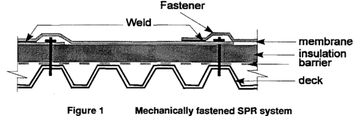
experiencing environmental forces such as wind and temperature and it may be either the Built-Up Roofing system (BUR) or the Single-Ply Roofing systems (SPR). Both the BUR and SPR systems have five basic components: deck, insulation, barriers, membrane and attachment systems. In general, the BUR system has more than one ply of membrane while the SPR system, as the name implies, has only one ply. In SPR systems, the waterproof membrane is held in place using one of the following methods: =, Mechanically-fastened SPR system: In which the waterproof membrane is attached to the roof
substrate either along strips or at numerous points using fasteners. The attachment includes mechanical fasteners and metal strips or plastic strips. As shown in Figure 1, the attachments are also covered with a membrane so that the roof top surface is impermeable to water.
Fastener
membrane
insu!ation
bamer
deck
Figure 1 Mechanically fastened SPR system
=, Adhered SPR system: the membrane is completely attached to the substrate by means of a solvent or water-based adhesive or hot bitumen (Figure 2).
Adhesive
\
membrane
insulation
barrier
deck
Figure 2 Adhered SPR system
=
The loose-laid method (ballasted configuration): Rolls of waterproof membrane are unrolled onto the prepared roof surface. The seams formed at adjacent roll lengths are attached at the perimeter and projections of the roof. The completed membrane is held down with gravel or concrete pavers (Figure 3).Stone.
membrane
insulation
barrier
deck
Figure 3 Loose laid SPR system
Figures 1 through 3 present the basic component arrangements of the SPR systems in a generic form. Numerous combinations of SPR system are available based on the component selection. Typical components used in SPR systems are organized as follows:
Deck
Steel, Wood, Concrete, Fiber and Composite boards. Insulation
Extruded or Expanded Ploy- Styrene, Urethanes, Poly-lsocyanurate, Phenolics, Glass and Mineral Fibre.
Barriers
Vapor barrier, Air barrier, Fire barrier Membrane
EPDM, PVC, TPE, TPO, Hypalon, Reinforced varieties, Neoprene, Modified bituminous Attachment Systems
Spot fasteners, Bar strap and anchors, Adhesive, Stone, Heavyweight pavers, Lightweight interlocking pavers, Ballast, Concrete tiles with ship laps.
Design of a roofing system also involves the selection of compatible components. Component selection plays an integral role in the performance of roofing systems. Special regard should be given to wind uplift and fire resistance, warranties and guarantees, testing and inspection and compatibility specifications during the selection process. The present study focusses on the mechanically fastened SPR systems. This type of roofing assembly has proven to be the most appropriate arrangement for lightweight roofs
(Gerhardt et al. 1989).
12
PROBLEM DEFINITION1.2.1 PROBLEM
Wind flow over a typical roofing system is shown schematically in Figure 1. It can be observed from the figure that wind flow creates two types of pressure components, namely, negative pressure. P, and positive pressure,
P,.
P, is created by flow separation on the exterior side of the roof. P, is known as building internal pressure. It is generated by the pressure difference induced by the wind and the temperature gradient across the envelope and the mechanical ventilation system installed in the building.P, is especially important for large span industrial buildings, supermarkets and structures of this nature. Since such building envelopes are usually highly wind permeable, the wind - induced internal pressure sometimes may equal the outside negative pressures. The design wind uplift is the vector addition of these pressure components. Wind induced pressure on a roofing membrane will have a static
component (mean pressure) and a transient component. The latter varies as a random process and its dominant frequencies depend on the frequency of the upstream wind and geometry of the building. Thus the wind uplitt pressure is time dependent.
Figure 4 Wind flow schematic over roofing system
As well, the design wind pressure will vary spatially over the roof. It has the largest values at the corner and perimeter due to flow vortex and will be moderate in the middle portion of the roof. This is
demonstrated
in
Figure 5 which represents typical mean pressure coefficients measured in the wind tunnel. The data is for a square plan building exposed to oblique wind direction. It is evident from thefigure that an imaginary line of symmetry exists along the diagonal of the roof. The pressure coefficients are maximum near the two leading edges. They decrease as one moves away towards the leeward edge. For this roof configuration a zero pressure coefficient represents occurrence of flow reattachment. After reattachment, the coefficients are positive. Thus it is clear that the wind induced pressures will vary with respect to space.
re coefficient din
auas the roof
Figure 5 A typical spatial variation of wind pressure on a building roof. The response of the roofing system is also dynamic. In other words, wind induced loads on the
membrane can reach the structural supporting system through two load paths, namely, pneumatic load path and structural loadpath. In the pneumatic loadpath the load is shared among the layers
(membrane, barrier, insulation) by differences in pressure across them. In the structural load path the loads passes through the fasteners. If fluctuations of external wind pressures are slower than the membrane response time then the loads are transmitted through membrane tension to the fasteners, i.e., structural loadpath. For fluctuations faster than the membrane response time, the load will be
transmitted through pneumatic actions. Measurements by Cook, (1992) showed that the higher the applied suction the greater the proportion borne directly by the membrane (structural path). Gerhardt and Kramer (1992) reported that for common spot fastener designs, the force applied on a fastener was approximately 2.5 times the wind uplift force.
From the above discussion, it is clear that the problem of wind induced effects on roofs is both time and space dependent. This has been found true both for the driving force and for the system response.
Therefore, a proper three-dimensional and time dependent (dynamic) analysis is essential for adequate estimation of wind effects on roofs.
1.2.2 FAILURE MECHANISMS
Due to the dynamic nature of the wind uplift forces, different failure mechanisms can be recognized for mechanically attached SPR systems:
Fastener backout: the fastener unscrews upwards and punctures the membrane (Figure 6). Fastener pullout: caused by fatigue cracks in the deck round the bore hole; the fasteners pull out of the deck leading to failure of the attachment systems (Figure 7).
Zipper effect: where failure of one fastener either due to backout or pullout leads to the failure of adjacent fasteners because of force redistribution.
Attachment plate deformation: occurs in the case of spot attachment systems; plates are deformed upwards as a result of the tendency of the membrane underneath to lift and arch under wind uplift forces (Figure 8). This type of failure is considered the most common failure mode reported by field observations (Gerhardt and Gerbatsh, 1991) and ultimately causes the tearing of the membrane at the attachment points.
Membrane tearing: in addition to the above, membrane tearing also caused by excessive ballooning (Figure 9).
Both fastener pullout and membrane tearing are fatigue problems and are not caused by one-time overloading (Gerhardt and Gerbatsh, 1989) of the roofing system.
Figure 6 Fastener backout (Sarnafil specification manual)
Applicatron of Numerical Models
-
...
State-of-the-drtFigure Typical cracks on a steel deck after fastener pullout failure (Baskaran and Dutt, 1995)
Figure 8 Plate deformation (Sarnafil specification manual)
Figure 9 Membrane ballooning (Thomas, 1993)
1.3 SCOPE OF THE REPORT
Recently, lnstitute for Research in Construction of the National Research Council Canada (IRCINRC) has started a project on the dynamic evaluation of roof attachment systems in collaboration with the lnstitute for Aerospace Research of the National Research Council Canada (IAWNRC). Figure 10 summarizes the different aspects of the ongoing project. In this project, test procedures and numerical models will be developed to evaluate the performance of mechanically attached roofing systems under dynamic wind loading conditions. The analyses and the test results will be combined to produce a design manual for the roofing industry. The experimental part includes laboratory tests to evaluate materials and systems performance and wind tunnel unsteady load measurements. The computer modeling involves the development of a Finite Element Method (FEM) structural model and a CFD wind-loading model.
The current report is mainly focused on the numerical modeling of roof assemblies and thus the remaining part of the report will:
present a review of the state-of-the-art for the application of numerical models used to evaluate the performance of roofing systems (Chapter 2).
report research findings and identify future research areas based on the knowledge gathered from review of literature (Chapter 3).
Dynamic Evaluation of Roofing Systems
Experiments
s
-(runnel)
Figure 10 IRCINRC project flow-chart
CHAPTER 2
STATE-OF-THE-ART
2.1 INTRODUCTION
Recently, application of numerical models to study the performance of roofing systems has increased considerably. The present review groups, in a chronological order, various numerical studies in two categories based on the type of roofing system, namely, studies related to:
1. Adhered and Ballasted SPR systems and 2. Mechanically attached SPR systems
2 2 ADHERED AND BALLASTED SPR SYSTEMS
Koike et al (1978) investigated membrane failure as a result of fatigue rupture of substrates. Substrates such as rigid plastic foams and concrete planks were reported to be susceptible to relatively large joint movement which led to membrane fatigue. The membrane ability to withstand these large movements were investigated. Strains induced in multi-ply membranes, asphalt felts and reinforcing components, were modeled using differential equations. These equations are based on the theory of elasticity. First, the strains in fully bonded membranes were analyzed. Second, modifying the boundary conditions, strain increases in the remaining unbroken felts were investigated up to the rupture of the entire bond. The effects of the installation method of loosely laying membranes over joints in substrates was also analyzed. This has been performed by solving two simultaneous differential equations for the bonded and loosened parts so as to satisfy the boundary conditions.
Study considered only one component of the roof assembly, namely. the membrane.
Analysis was carried out for the substrate movement-induced strains and no provisions were made for other types of load-induced strains.
Non-linear membrane response was obtained through incremental linear analysis.
In a pioneer study, Lewis (1980) investigated the applicability of Finite Element Method (FEM) to
calculate the thermal-induced stresses for a bituminous built-up membrane. The membrane was placed on fibrous glass insulation boards that sits over a metal deck. The investigated roof design geometry
(Figure 11) had single span steel joists of varying depths at 1.5 to 1.8 m intervals and 38 mm deep with 22 gauge corrugated steel deck. The fiberglass system was double layered each 47.6 mm thick. The primary objective of the study was to evaluate the thermal-induced stresses in the membrane placed on gaps between adjacent roof insulation panels by defining two types of joints, namely, "over-lapped" and "non-overlapped" (Figure 12). To simulate the proper moment of inertia, the steel deck was represented by an equivalent thickness rectangular layer. Thus, the corrugated deck is simulated by a 9.93 mm thick layer. The study also investigated the effect of several parameters on membrane stresses. Studied parameters included: insulation board modules, insulation thickness, gap width between insulation boards, deck thickness, distance between roof deck and structural supports, insulation gap location with respect to roof deck structural supports and finite-element grid refinement.
Findin@
Preliminary analyses indicated that membrane stresses are adversely affected by not overlapping insulation panels and by increasing either insulation thickness or stiffness.
.
The study showed that the stress levels in the membrane at locations above a continuous gap through the two insulation board layers were higher (63% increase) as compared to the configuration having no gaps.VIIIITE ELtUINt MODEL Nal
~ ~ I I I L U I I I I W I L I IIMIUI
Z ~ I I I I ~WII~~MLYS
moor t*#DLA1*.
Figure 11 Typical built-up roof section showing location of finite element model (Lewis, 1980)
-
LOWER
TOTAL
GAP
GAP
(A)
OVERLAP JOINT
( 0 ) NON-OVERLAP
JOINT
Figure 12 Different types of joints between insulation panels (Lewis, 1980)
Limitations:
No experimental verification of the model data was carried out.
.
Analysis involved only isotropic behavior of the materials.Design geometty and load histories were not included in the analysis,
Study did not consider the time and temperature dependence of material properties.
A linear finiteelement method of analysis was used by Rossiter and Batts (1985) to calculate stresses induced in a singleply roofing membrane due to thermal gradients. The study utilized the MacNeal- Schwendler Corporation (MSCINASTRAN, 1972) FEM code. An eight node isoparametric quadrilateral element was used in the analysis.
The element can simulate membrane or plate bending applications. Two roofing systems were modeled and analyzed to calculate the stresses induced by linear thermal gradients across the roof systems. As shown in Figure 13a, the first roofing systems consisted of a 1.5 mm totally adhered EPDM (Ethylene Propylene Diene terpolymer Membrane) two layers of fibrous glass insulation board each 48 mm thick
and a 22 gauge steel deck. In the second system the EPDM was looselaid and subjected to a uniform
surface load of 122 kg/m2 to represent the ballast weight. As shown in Figure 13b both roofing systems
were subjected to temperature differential of 55°C (1 OO0F), having membrane surface temperature as 24" C and the bottom surface (metal deck) as 79°C. During the analysis, the following assumptions were made:
only a 2D (plane strain model) roofing system was considered in the analysis.
.
membrane was stress-free at 24°C.material properties were assumed isotropic and invariable with temperature and therefore the model was linear and elastic.
membrane had no seams, flaws, or other stress concentrations.
totally adhered membrane numerical model did not include an adhesive layer; instead the membrane was constrained at all points.
loose-laid membrane was only constrained at the edges and it could subsequently slide horizontally with respect to the insulation.
6 mm Gap EPDM F8bewI-s -el Dec;k Purlin Support
-
H 7200 Ha
'
"
AT-
= sSC 79-C MembraneInrn~IBtiM 48- F E M Element mesh
Figure 13 a) Configuration of the modeled roofing systems
b) Typical loading of the roofing system c) Finite element mesh used in the analysis
Material properties used in the finite analysis is shown in Table 1. Both the totally adhered and loose-laid membrane systems were modeled with a ballast surface load of 122 kg/m2 to represent the ballast weight. This surface load was included for a totally adhered system for comparison purposes. The finite element mesh used for both the investigated systems is shown in Figure 13c. The mesh was comprised
of 48 elements for a length of 457 mrn and was repeated 16 times (768 elements) to represent the total roof length.
.
For the adhered system, the results indicated that the temperature-induced membrane stresses were approximately 0.20 MPa at membrane locations corresponding to the gaps between the insulation boards. This peak stress is about 20 % of the ultimate tensile strength of the membrane. Theultimate strength was measured as 12 MPa in the lab at
-
18°C for a relatively high loading (50 cmlmin).For the loose-laid system, the corresponding peak stresses were about 0.12 MPa. These results were compared with the experimental result of Dupuis (1981). Measured stress values ranged from 0.07 to 0.33 MPa, for a loose-laid ballasted roofing system with elastomeric membrane subjected to a temperature drop of approximately 55%.
Table 1 Material properties of roofing System components (Rossiter, 1985)
The low level of stresses (0.12 to 0.20 MPa) for both systems are due to the low modules of
membrane material. Also it had been explained that many synthetic materials embrittle and showed increases in modules and reduction in ultimate strength upon aging.
Parametric studies have also been conducted for the totally adhered roofing configuration by calculating peak level of temperature-induced membrane stresses. Investigations include: effect of the membrane modules (2 to 80 MPa), coefficient of linear expansion (330 x ~ O - ~ / ~ C and 660 x "C) and membrane thickness (1.1 to 1.5 mm).
Results revealed that as the membrane modules increased, the temperature induced membrane stresses increased in nonlinear fashion from 0.13 to 6.5 MPa. When the coefficient of linear expansion was reduced from 660 x 1 O - ~ / O C to 330 x 1 o-~/'c, the peak induced stresses decreased from 0.20 to 0.13 MPa. Membrane thickness effect was found to be negligible.
Limitations:
Only
2D
geometry was modeled for the roofing assembly and a constant exterior load condition was applied.Study did not consider the time and temperature dependence of material properties. Analysis involved only isotropic behavior of the materials.
Zarghamee (1990 a) studied the effect of the wind pressure on an inflated single-ply roofing membrane and its attachment mechanism (Figure 14).
External pressure
=
P,
lnsulatlon
Inflitration
I steel deck
Rate
=
Internal pressure
=
P.
Figure 14 Inflated membrane and various pressure regions
The governing differential equations, expressed in terms of the pressure underneath the inflated membrane, were derived by using the flow continuity condition and solved numerically through iterative procedure. Computations were performed for a constant internal pressure, Pi, and a sinusoidal varying external pressure,
Pe.
The frequency range of the exterior sinusoidal pressure was determined based on wind pressure power spectra values measured from a wind tunnel for a roof of a square plan building model. Zarghamee (1990b)
calculated three values, namely, volume under the inflated membrane, Vb; vertical reaction per unit length at the boundary of the membrane, R and tension per unit width in the membrane, T to represent the membrane response. The three values were calculated using the following equations:where "b "bo A Pe peo Pet Pb E h
volume under the inflated membrane;
volume of trapped air between the membrane and roof deck; projected area of the inflated membrane;
pressure outside the inflated membrane = PeO
+
Pet sin at; static component of wind pressure;amplitude of the cyclic exterior pressure component. pressure inside the inflated membrane;
modules of elasticity of the membrane; membrane thickness;
one-half of the distance between supports for a strip membrane or the radius for a circular membrane
dimensionless coefficients dependent on the shape of the membrane;
A developed mathematical model was then used to study the roofing system response. The effects of several parameters such as membrane stiffness, membrane thickness, membrane strip dimension, values of the external pressure and period of fluctuations of the external pressure were also investigated. The transient response factor (TRF) was used to quantify the results. TRF is defined as the ratio of the fluctuating component of pressure difference across the membrane thickness to the fluctuating
component of external wind pressure. The results obtained from Equations 2.1 through 2.3 were
compared with those obtained using FEM analysis. A membrane measuring 3.7 m x 7.3 m was attached to bars 2.1 m apart running parallel to the shorl direction. The membrane was assumed to be linearly elastic with E = 95.8 MPa, h = 1.2 mm and y = 0.4. Computed deflections, tension and vertical reaction values are compared in Table 2.
Table 2 Comparison of the results with the FEM analysis (Zarghamee, 1990)
Findmos.
It was shown that TRF depended on various factors such as the rate of air flow into the space underneath the membrane, stiffness of the membrane, upstream wind characteristics (period of fluctuating wind, mean hourly wind velocity and value of external pressure) and on the dimensions of the membrane strip.
The study also reported that the failure mechanism of single-ply roofing systems is initiated by air infiltration into the space underneath the membrane followed by ballooning of the membrane with fluctuations in wind pressure.
.
If the membrane was laid flat on an air impermeable roof deck with no path for air movements then the membrane would not respond to wind fluctuating forces.. .
LNn,tations:
.
Analysis did not consider the realistic wind velocity profile and flow conditions over the building roof..
Study applied only the conselvation of mass law and excludes the momentum changes of the airflowmovement.
Only the membrane was considered in the analysis and the contribution of the whole roof assembly in the response was ignored.
The study was quasi-static because it ignored the dynamic effects (inertial effects) of the infiltrating air.
Simplified approach developed by the study produced constant tensile stress across the membrane strip
-
as shown in Table 2-
and thus the model is insensitive to the variation of stresses across the membrane,Brodland et al. (1993) studied the effect of fullyadhered membrane response to differential movements between adjacent substrates. These differential deformations were produced by seasonal temperature changes and aging. Theoretical formulation was based on large strain analysis. A PC based finite element software called REMA (REinforced Membrane Analysis) was used to perform the analysis. REMA analyzed a fully adhered roofing membrane. It consisted of a mat-reinforced base sheet bonded to a rigid substrate and cap sheet. The cap sheet contained both a polyester scrim and a glass
reinforcement bonded to the top of the base sheet (Figure 15). At the center of the sample there was a joint in the substrate. The half length of the sample was 200 mm. The base sheet was measured as 2 mm thick. The glass reinforcement with a thickness of 0.5 mm was placed mid-way through the sheet thickness. The cap was measured as 3.5 mm thick and its reinforcements were located at its center. The gap was widened by specifying the displacement of the substrate and the analysis was performed for a temperature of -5°C.
Figure 15 Membrane system subjected to in-plane loading (Brodland et al., 1993)
Findinos:
Study computed the sequences of the membrane component failures due to gap widening (Figure 16).
Comparison for the load-deflection curves produced by the
FEM
and measured data from laboratories tests was also attempted (Figure 17).Study was carried out for the analysis of only one component of the roof assembly, namely, the membrane.
Analysis was carried out for the substrates movement-induced strains and no provisions for other types of load-induced strains such as wind induced loads.
Study did not consider the time and temperature dependence of the material properties.
Bienkiewicz and Sun (1993) developed a numerical model to simulate wind loading on roofing systems with loose-laid ballastpavers. The numerical model assumed Darcy's law for modeling the flow beneath and between pavers. The pressure distribution along the paver edges was assumed to be piecewise linear. The mathematical model was obtained for a generic paver system based on the following assumptions:
pavers had the same dimensions and were uniformly spaced; paver thickness was small compared with the other two dimensions;
flow fields over and between pavers were assumed incompressible and the space is filled with porous media of constant permeability;
distance between pavers and the roof deck was small compared to pavers thickness;
.
pressure distribution between pavers varies linearly; andFigure 16 Deformation of membrane due to substrate displacement (Brodland et al., 1993), (a) Un-deformed mesh; (b) Deformed mesh just prior to failure of lower glass mat; (c) Deformed mesh just prior to failure of upper glass mat;
(d) Deformed mesh following failure of upper glass mat
as shown in Figure 18, both external and internal pressures are distributed piecewise linearly along the edges of each pavers.
The numerical model developed by Bienkiewicz and Sun (1993) can be briefly documented as follows:
=> First, the Lapiace equation was obtained based on Darcy's Law and incompressibility assumption.
+
By applying the boundary conditions on the developed Laplace equation, a boundary-value problem ina rectangular domain was derived.
+
Expression of flow velocity beneath pavers was then determined by employing separation of variables technique.+
Afler determining the velocity field, expressions of pressure distribution between the pavers were obtained.=> Computed flow between and beneath pavers were then utilized in mass conservation equations for different control volumes. This resulted in a system of linear algebraic equations which related the unknown underneath pressure to the known external pressure.
-
Load (N/mm) -+- FE Analysis-
-mental 0 5 10 15 olhplaamenl (mm)Figure 17 Predicted and experimental load-deflection curves (Brodland et al., 1993)
I
(a) overdl viewI
@) side view
(c) pressure distribution on a paver
Figure 18 Configuration of a generic roofing paver system (Bienkiewicz and Sun, 1993)
A developed mathematical model was used in analyzing two types of pavers; pavers A and B. Both pavers were tested in the wind tunnel ( Bienkiewicz and Sun, 1992) and the external and underneath pressures were measured. Paver A was a 1.25 scaled model (24 x 18 x 3 mm) with a flat underneath surface and located in a windward roof corner of the tested building. The power-law exponent of the mean velocity profile of the flow was 0.14 and the turbulence intensity at building roof height was about 20%. The incidence of the flow to the building was 45". Paver B, on the other hand, was a prototype concrete paver (419 x 298 x 35 mm) and had a complex underneath geometry and interlock between them. It was placed on an inclined (I@) platform representing a building roof. The atmospheric boundary layer flow properties for testing paver B was normal flow, power law exponent of 0.189 and turbulence intensity at roof height of about 6.5%. The measured external pressure was used as input for the mathematical model to calculate the underneath pressure and was compared with the measured one. Effects of paver size and geometry on the roof wind loading were also studied.
.l%dw
Investigation showed that for a given external pressure distribution, the underneath pressure depended only on the ratio of the space between the pavers to the space underneath the pavers. When the ratio approached zero, the underneath pressure distribution is mostly uniform. On the other hand, the underneath pressure distribution depicted the external pressure distribution when the ratio approaches infinity.
Study revealed that for a given aspect ratio of the paver, the maximum uplift pressure (the difference between the external and underneath pressure) increased with the decrease of the paver size. Also, for a given paver size, the maximum uplii increased with the increase of the aspect ratio.
Developed model may not be applicable to other pavers with a different geometry. Model excluded the turbulence flow mechanism that are developed beneath the pavers. Model lacks the application of conservation mass law together with momentum.
2.3 MECHANICALLY ATTACHED SPR ASSEMBLIES
Mechanically fastened SPR systems fall into two basic categories, spot fastener and strap fastener systems, based on the membrane attachment systems. In the spot fastener system (Figure
I )
the membrane is fixed at discrete points. In strap fastener systems, parallel battens are used to restrain the movements of the membrane. These systems present a challenge for the designers to safely design them while considering the different aspects related to their behavior. Questions such as the magnitude of the balloon height of the membrane, membrane stresses and fastener stresses must first be answeredbefore a safe design can be achieved. Contrary to the fully adhered and ballasted SPR systems,
(Figures 2 and 3), only little research has been carried out to investigate the performance of mechanically attached SPR systems. In the following section a record of the efforts to study these systems are
reviewed.
Easter (1990) applied the Finite Element Method (FEM) to EPDM membranes to investigate its response to wind uplifl forces. The FEM model was built using PATRAN program whereas the analysis was done using the SAFEM soflware. A membrane shell element was used in the numerical simulation. In the analysis, the edge nodes were restrained against movements in all directions. To account for the excessive membrane deformations due to the wind suction, large geometry deformation's capability was implemented in FEM. The force required to restrain the line or batten was found at every node point. The size of the modeled membrane was 1.525 x 2.743 m to compare to the traditional factory mutual, (FM) 5 x 9 wind uplifl test. An EPDM membrane having Young's modules of 2.689 MPa and battened in the seam was modeled. Batten strips were 2.134 m apart and were fastened at 0.305 m intervals. Batten strips were placed parallel to the short edge (1 524 m) and they were approximated by fixing a line of nodes with zero width.
.l3dms
Results indicated maximum fastener load of 1.245 kN and strains of 90% for 5.746 kPa (120 psf) pressures.
.
Ballooning phenomenon was predicted by the analysis and its maximum height was calculated as 1.829 m (Figure 19).Stresses at edges of the table were found to be larger than those at the batten plates because of the edge effect (Figures 20 and 21).
As shown in the Figure 22, a single ply membrane with dimension of 3.6 x 7.2 m was also analyzed for a pressure of 4.309 kPa (90 ps9 to compare with FM 12 x 24 test. In this case, the ballooning height was calculated as 2.438 m.
Figure 23 shows long side stresses for this model whereas Figure 24 presents the computed vertical forces at the batten.
Study concluded that FEM modeling could substitute the large scale wind uplifl testing for roofing system subjected to very high loads and only small scale tests were needed.
.
Similar to FM test procedure, the dynamic nature of the external pressures was not modeled. Only membrane was modeled without considering other roofing components such as insulation and decks.It was only possible to obtain the vertical forces on the batten strip.
Figure 19 Deformed shape at 120 psf of 5 x 9 table with batten (Easter, 1990)
Figure 20 Long side direction stresses at 120 psf for 5 x 9 table (Easter, 1990)
Figure 21 Short side direction stresses at 120 psf for 5 x 9 table (Easter, 1990)
I
Figure 22 Layout of 12 x 24 test with 3.04 rn specimen (Easter, 1990) A
Application of Numerical Models
-
State-of-the-At7 PagemB C D
(0 0. 6 01 (2 0. 6 0)
SYMMETRY P M E
A
I
Figure 23 Long side stresses for 12 x 24 table at 60 psf (Easter, 1990)
I
0 10 20 30 40 50 60 .70 80 90 100
MODULUS FACTOR
I
Figure 24 Edge Batten peak vertical force versus modules for 12 x 24 table (Easter, 1990)
Gerhardt and Kramer (1 992) calculated the membrane stresses and fastener forces under static loads using the theory of a prestressed membrane. These efforts were made for collecting additional data during the development of UEATc test procedure (Gerhardt and Kramer, 1988). At any point with coordinates (x, y) under a constant load w, the membrane stresses, nx and ny as well as the vertical deflection, Z, were calculated through iterative procedure from the following equation:
At the fastener locations, the membrane deflection, 2, was considered as zero. Using these boundary conditions, the membrane stresses and fastener loads were obtained. Gerhardt and Kramer (1 992) investigated the effect of modules of elasticity of the membrane and membrane thickness on the membrane deformation. For their calculations, the moduli were in the range of E = 2 MPa to 160 MPa. Equation 2.4 was applied for two typical fastening cases (Figure 25), namely, a field of five-by-five fasteners, and a field of nine-by-nine fasteners. The first case had dimensions: width (m) = 1.2 m; length (I) = 3.8 m; fastener row separation (a) = 0.90 m; and fastener spacing (b) = 0.25 m. The second case dimensions are: m = 2.25 m; I = 4.760 m; a = 0.5 m; and b = 0.25 m. Both cases were analyzed under the effect of a wind suction, p, equaled 1800 Pa. The theoretical fastener loads, Wth, were calculated by multiplying the wind pressure, p, with the influence areas, Ainf. as follows:
Wth
=p+
A
infW I ~
= 1800*0.90*0.25
=405N
...
(2.5)Wza
= 1800*0.50*0.25
=225N
Findinas
For a smaller aspect ratio, atb, and larger ratio, d b , (the second case), the recorded fastener loads were larger with the central fastener carrying the highest load about 78% of the theoretical fastener load. Also upon the failure of the central fastener, an increase of approximately 1.4 in the load of the next fastener was recorded.
Influence of membrane material had very little effect on the distribution of fastener loads and is negligible.
Roofing system components such as insulation and decks were not considered in the study. Modeling technique was only able to compute fastener vertical forces.
.
R was only possible to apply a constant static load.Dynamic nature of the external pressure was not considered.
Modeling techniques of the applied FEM software is not well documented.
I I
T
m=1200mm__0-
-
I
I = 3800mm-
without failure with faiiure of 11113 0.114 0.118 0.190 0.116 0.193 0.198 0.306 0.627 0.630 0.314 0.649 0.857 0.358 0.778 0.780 0.343 0.746 .I.
a) Small test specimen
without failure with failure of Vi5
3 4 5
111 0.993 0.993 0.993 0.993 1.000 1.033
N 1 1 1 1.013 1.053 1.375
V 1 1 1 0.980 1.050
J.
b)
Extended Roof Area (a = 500 mm; b = 250 mm; 1 = 4760 mm; m = 2250mm)
Figure 25 Fastener load before and after failure of the central fastener (Gerhardt and Kramer, 1992)
CHAPTER
3
CONCLUSIONS
3.1 PAST RESEARCH ACTIVITIES
-
SUMMARYStudies applying numerical models for the static and dynamic evaluation of SPR systems have been systematically reviewed in the previous chapter. Numerical modeling approach found to be
advantageous in understanding the system performance. For example, computer models can be economical and efficient tools to perform parametric studies such as variation in the applied wind loading as well as geometrical and material changes in the roofing systems.
Similarities exist among the reviewed studies in the modeling of deriving forces, assembly details and numerical techniques used. They can be listed as follows:
Driving Forces
Fluctuations of the wind load variations on the roofing system are not modeled and thus applied loads did not vary with time nor space.
Assembly Details
Majority of the studies modeled only roofing membrane ignoring the contributions from other components (insulation and decks ) in the system response.
Numerical Technique
Researchers applied either the FEM or simplified technique in modeling the SPR systems.
On the other hand, studies varied in the parameter evaluation and they are summarized as follows:
Studies have been carried out using the FEM to:
determine induced stresses in SPR membranes due to thermal gradients across the roof system. investigate the mechanical failure behavior of fully adhered SPR under in-plane loading conditions.
.
investigate the static ballooning response of mechanically attached SPR membrane subjected to thewind uplii force.
Studies have also been carried out using simplified techniques to:
predict the effect of wind pressure (i.e. dynamic component) on the inflated SPR membranes and its attachment mechanism employing a quasi-static analysis.
investigate the fatigue failure of the fully bonded membranes caused by the fatigue rupture of the substrates by solving the governing differential equations.
.
simulate wind loading distribution on SPR system with ballasted pavers by applying Darcy's law for flow movement and assuming linear pressure variations.3.2 AREAS FOR FUTURE RESEARCH
To have a software capable of performing complete system design would be ideal for the roofing designers. In other words, it is preferable to have a numerical tool to investigate and design roofing systems for various components subjected to different induced stresses such as wind, thermal and rain. Nevertheless, the present research focuses mainly on the wind effects on SPR systems. Thus, the following identification for further research is also limited to the same. As demonstrated in Chapter 1, the wind induced effects on roof is both time and space dependent. The time dependency mainly comes from the driving force, namely, wind induced pressures. On the other hand, the space dependency reflects the fact that the roofing system response and induced stresses do vary in a three dimensional fashion. Review of the state-of-the-art, presented in Chapter 2, reveals the vital need for further research into the following areas:
1. Comprehensive modeling of wind loading conditions including the fluctuating component.
2. Systematic modeling approach for the roofing assembly details by considering its three dimensional variations.
3. Predicting wind pressure distributions on roofs using Computational Fluid Dynamics (CFD). 4. Proper consideration in the analysis for the roofing system components details such as spot
attachment anchors, insulation, decks, etc.
5. A model to develop design guidelines by studying the effect of different parameters such as changes in fastener spacing, membrane sizes and variation in the exterior loading.
6. Investigating the effect of load combinations such as thermal and wind.
7. Introducing the time, thermal and space dependence of material properties in the analyses.
Research efforts are in progress at IRCINRC mainly addressing the first three items of the above listing. In a second report, "Application of Numerical Models for the Dynamic Evaluation of Roofing Systems- Part 2: Present Focus" preliminaryfindings have been documented (Kashef and Baskaran,l995).
CHAPTER 4
REFERENCES
1. Baskaran, A. and Dutt, 0. (1995). 'Evaluation of Roof Fasteners Under Dynamic Wind Loading", Proceedings of the lnternational Wind Engineering Conference, New -Delhi, India, January 8
-
13, pp. 1207-
1218.2. Baskaran, A. and Kashef, A. (1995). " Application of Numerical Models for the dynamic Evaluation of Roofing Systems
-
An Introduction:, Proceedings of the Third Annual Conference of the CFD Society of Canada, Banff. Alberta, June 25-27.3. Bienkiewicz.
6.
and Sun. Y. (1993). "Numerical and Experimental Studies of Wind Loading on Loose-Laid Roofing Systems", Colorado State University. Civil Engineering Department, Fort Collins, Colorado, USA.4. Brodland, G., Wayne. D., Marcus, J. and Burnett, E.F.P. (1993). "Large-strain Analysis of Reinforced Membranes", Journal of Engineering Mechanics, Vol. 119, December 12, pp. 2461- 2477.
5. Busching, H.W and Rossiter, W.J., Jr. (1987). "Review of Preliminary Performance Criteria For Tensile and Tensile Fatigue Tests of Bituminous Roofing Membranes", Durability of Building Materials. Vol. 4, April 4, pp. 323-342.
6. Busching, H.W. and Courville, G.E. (1981). "Proceedings of the Department of Energy-Oak Ridge National Laboratory Workshop on the Mathematical Modeling of Roofs", Conference-81 1179. Oak Ridge National Laboratory, USA, November 3-4, 362 pp.
7.
Cook N.J. (1992). "Dynamic Response of Single-Ply Membrane Roofing Systems", Journal of Wind Engineering and Industrial Aerodynamics. Vol. 41-44, pp. 1525-1536.8. Easter, M.R. (1990). "Finite Element Analysis of Roofing Systems", Roofing Research and Standards Development: American Society for Testing and Materials, Philadelphia, Vol. 2, STP 1088, pp. 138-151.
9. Gerhardt, H.J. and Gerbatsch, R.W. (1989). "Wind Loads on Single-Ply Membranes". The Construction Specifier, November, pp. 60-71.
10. Gerhardt, H.J. and Gerbatsch, R.W. (1991). "Wind Resistance of Mechanically Attached, Single Ply Systems - Fastener Load, Safety Considerations and Optimal Fastener Patterns". Proceedings of the 1991 International Symposium on Roofing Technology, National Roofing Contractors Association, Rosemont, Illinois, USA.
Kind, R.J. and Wardlaw. R. L. (1985). "Wind Tunnel Tests on Loose-laid Roofing Systems for Flat Roofs", Second International Symposium on Roofing Technology, National Roofing Contractors Association, Chicago, Illinois, USA, pp. 230-235.
Koike, M., Tanaka, K. and Tomiita, T. (1978) "Strains in Multi-Ply Membranes Caused by Joint Movement in Substrate", Report of the Research Laboratory of Engineering Materials, Tokyo Institute of Technology, Japan, No. 3, pp. 145-177.
Lewis, J.E. (1980). "Preliminary Stress Evaluation of the Effects of Gaps Between Roof Insulation Panels", Journal of Thermal Insulation, Vol. 4, pp. 3-36.
Oak Ridge National Laboratory (1994). 'A Guidebook for Insulated Low-slope Roof Systems', IEA Annex 19, February, Oak Ridge, Tennessee, USA.
Rossiter, W.J., Jr. and Batts, M.E. (1985). "Finite-Element Analysis of Temperature Induced Stresses in Single-Ply Roofing Membranes", Durability of Building Materials, Vol. 2, pp. 195-208. Zarghamee, M.S. (1990). "Wind Effects on Single-Ply Roofing Systems", Journal of Structural Engineering, Vol. 116, No. 1, pp. 177-1 87.
Zarghamee, M.S. (1990). 'Dynamics of Roofing Membrane in Wind", Roofing Research and Standards Development, Vol. 2.. Proceedings of the ASTM Symposium, San Francisco, California, USA, June 17, pp. 152-1 62.
Zeinkiewicz, O.C. (1971). "The Finite Element in Engineering Science", 2nd Edition, McGraw-Hill, London, 521 pp.
CHAPTER 5
BIBLIOGRAPHY
This chapter provides a handy and quick reference on roofing systems performance. Past studies have been assembled into four groups; driving forces (pressure) studies, systems studies, membrane studies and attachment (fastener) studies. Each group is further divided into two sub-groups: technical papers and articles.
n n a Forces [Pressure) Studies Technical Papers:
1. Anon (1986). Wind Load and the Single-Ply Solution", Civil Engineering, (London), November- December, pp. 27-28.
2. American Society of Civil Engineers (1995). "Minimum Design Loads for Buildings and Other Structures", 7-95, New York, NY 10017-2398.
3. Baskaran, A. (1984). "Wind Loads on Flat Roofs with and without Parapets", Thesis Submitted in Partial Fulfillment of the Requirments for the Degree of Master Of Engineering at Concordia University. Montreal, Quebec, Canada.
4. Bienkiewicz, 9. and Sun, Y. (1992). 'Wind-tunnel Study of Wind Loading on Loose-laid Roofing Systems", Journal of Wind Engineering and lndustrial Aerodynamics, Vol. 41-44, pp. 1817-1828. 5. Cheung, J.C.K. and Melbourne. W.H. (1988). "Wind Loading on a Porous Roof", Journal of Wind
Engineering and lndustrial Aerodynamics, Vol. 29, pp. 19-28.
6. Davenport, A.G. and Surry, D. (1984). 'The Estimation of Internal Pressures Due to Wind with Application to Cladding Pressures and infiltration", Proceedings of the 1984 Wind Pressure Workshop, Brussels, Belgium, Vol. 164, pp. 1-17.
7.
Gerhardt, H.J. and Kramer, C. (1985). 'Wind Loads in Wind-permeable Facades", Journal of Wind Engineering and lndustrial Aerodynamics, Vol. 51, No. I , pp. 46-53.8. Gerhardt, H.J. and Kramer, C. (1986). "Wind Induced Loading Cycle and Fatigue Testing of Lightweight Roofing Fixations", Journal of Wind Engineering and lndustrial Aerodynamics, Vol. 23, pp. 237-247.
Gerhardt, H.J. and Kramer, C. (1988). 'Wind Loading and Fatigue Behavior of Fixings and Bondings of Roof Coverings", Journal of Wind Engineering and lndustrial Aerodynamics, Vol. 29. pp. 109-1 18.
Gerhardt, H.J. and Kramer, C. (1992). "Wind Safety for Single-Ply Roofs Under Time Varying Wind Load", Journal of Wind Engineering and lndustrial Aerodynamics, Vol. 41-44, pp. 1513-1524. Ho, T.C.E., Surry, D. and Davenport, A.G. (1991). "Variability of Low Building Wind Loads Due to Surrounding", Journal of Wind Engineering and lndustrial Aerodynamics, Vol. 38, No. 2-3, July- August, pp. 297-310.
Holmes, J.D. (1979). "Mean and Fluctuating Internal Pressures lnduced by Wind". Proceedings of the F i i h International Conference on Wind Engineering, Fort Collins, Colorado. USA.
Kareem, A. and Lu, P.C. (1992). "Pressure Fluctuations on Flat Roofs with Parapets", Journal of Wind Engineering and lndustrial Aerodynamics, Vol. 41-44, pp. 1775-1786.
Kramer, C. (1975). "Investigations of Wind Loads on Flat Roofs", Bauingenieur, Fachhochschule Aachen, Germany, Vol. 50, No. 4, April, pp. 125-132.
Lee, Y. (1982). "Distribution of Wind and Temperature Induced Pressure Differences Across the Walls of a Twenty Storey Compartmentalized Building", Journal of Wind Engineering and lndustrial Aerodynamics. Vol. 10, pp. 287-301.
Lin, J.X. and Surry, D. (1993). "Suppressing Extreme Suction on Low Building by Modiying the Roof Corner", 7th U.S. National Conference of Wind Engineering, University of California at Los Angeles Press, pp. 413-422.
Liu, H. and Saathoff, P.J. (1981). "Building Internal Pressure: Sudden Change", Journal of the Engineering Mechanics Division, ASCE, Vol. 107, No. EM2, pp. 309-321.
Paterka, J.A. and Cermak, J.E. (1975). 'Wind Pressures on Building-Probability Densities". Journal of Structural Engineering, American Society of Civil Engineers, Vol. 101, No. ST6, Paper 11373. Stathopoulos, T. and Dumitrescu-Brulotte, M. (1990). "Design Recommendations for Wind Loading on Buildings of Intermediate Height", Canadian Journal of Civil Engineering, Vol. 16, No. 6, pp. 91 0-91 6.
Stathopoulos. T. and Munteanu-Badian. V.L. (1993). "Wind lnduced Suctions on Flat Roof Comers: The Effect of Parapet Revisited", 7th U.S. National Conference on Wind Engineering, ,
University of California at Los Angeles Press, pp. 739-748.
Stathopoulos, T.. Surry, D, and Davenport, A.G. (1979). "Internal Pressure Characteristics of Low- Rise Buildings Due to Wind Action", Proceedings of the Fifth International Conference on Wind Engineering, Colorado State University, Fort Collins, USA, July 8-14, pp. 451-463.
Stathopoulos, T. and Baskaran, A. (1988). "Tubulent Wind Loading of Roofs with Parapet Configurations", Canadian Journal of Civil Engineering, Vol. 15, No. 4, August, pp. 570-578. Stathopoulos, T., Baskaran. A. and Goh, P.A. (1990). "Full-scale Measurements of Wind Pressures on Flat Roof Corners", Journal of Wind Engineering and lndustrial Aerodynamics, Vol. 36, NO. 2, pp. 1063-1072.
Stathopoulos, T. and Luchian, H.D. (1990). Wind Pressures on Buildings with Multi-Level Roofs". Journal of Wind Engineering and lndustrial Aerodynamics, Vol. 36, No. 2, pp. 1299-1308.
Stathopoulos, T. (1981). "Wind Loads on Eaves of Low Buildings", Journal of Structural Engineering, Vol. 107, No. 10, pp.1921-1934.
Stathopoulos, T. (1981). "Wind Pressure Functions for Flat Roofs", Journal of the Engineering- Mechanics Division, American Society of Civil Engineers, Vol. 107, No.5, pp. 889-905.
Stathopoulos, T. (1982). Wind Pressures on Low Buildings With Parapets". Journal of the Structural Division, American Society of Civil Engineers, Vol. 108, N ST12, December, pp. 2723- 2736.
Stathopoulos, T. and Baskaran, A. (1987). "Wind Pressures on Flat Rwfs with Parapets", Journal of Structural Engineering, Vol.113, No. 11, pp. 21 66-21 80.
Stathopoulos, T., Surry, D. and Davenport. A.G. (1981). "Effective Wind Loads on Flat Roofs", Journal of the Structural Division, American Society of Civil Engineers, Vol. 107, No. 2, pp. 281- 298.
Thomas, R.A. (1978). Wind Stresses of Large Flat Roofs", Ingenieursblad, Vol. 47, No. 3, March, pp. 72-76.
Ueda, H., Hibi, K. Tamura, Y. and Fujii, K. (1994). "Multi-Channel Simultaneous Fluctuating Pressure Measurement System and its Applications", Journal of Wind Engineering and lndustrial Aerodynamics, Vol. 51, No. 1, January, pp. 93-104.
Wacker, J., Friedrich, R., Plate, E.J. and Bergdolt. U. (1991). 'Fluctuating Wind Loads on Cladding Elements and Roof Pavers", Journal of Wind Engineering and lndustrial Aerodynamics, Vol. 38, pp. 405-41 8.
Articles:
1. Holmes, J.D. (1978). "Computer Simulation of Multiple, Correlated Wind Records Using the Inverse Fast Fourier Transform", Civil Engineering Transactions, Vol. 20, No. 1, pp. 67-74.
2. Kim, S. and Mehta, K.C. (1977). "Wind Loads on Flat Roof Area Through Full Scale Experiment", Texas Technical University, Lubbock Institute for Disaster Research, Report No. TTUIIDR-28D. 3. Prabhakar, N. (1992). 'Design of Low Rise Buildings for Wind Loads", The Indian Concrete
Journal, November, pp. 621-628.
4. Sheahan, J.P. (1993). "Understanding the Effects of Wind on Roofs", Roofing Siding Insulation, April 1993, p. 62.
5. Stathopoulos, T. (1989). "Local Wind Pressures on Roofs", Structural Design, Analysis and Testing, Proceedings of the Sessions at Structures Congress '89, San Francisco, California. USA, May 1-5, pp. 500-509.
6. Stathopouios. T. and Marathe. R. (1993). "Field Measurements of Wind-Induced Pressures on Roofs of Low Buildings", Proceedings of the Symposium on Structural Engineering in Natural Hazards Mitigation, I ~ i n e , California, USA, ISBN 0-87262-910-4, pp. 1515-1520.
7. Warshaw, S. (1984). "The Effects of Wind Uplift on Single-Ply", Roofing Specification Magazine, June, pp. 25-33.
8. Yoshida, M. and Hongo, T. (1 986). "Wind Tunnel Study of Wind Forces on Round, Flat and Domed Roofs with Long Spans in Profiled Flow", Annual Report, Kajima Institute of Construction Technology; Vol. 34, pp. 201-206.
Studies Technical Papers:
1. Fujii, K. (1992). "Discussion of Roofs
-
2". Journal of Wind Engineering and Industrial Aerodynamics, Vol. 41-44, pp. 1549-1550.2. Goodwillie, J.M., Jr. (1982). "Wind Resistance of Loose-laid and Spot-attached Single-Ply Roofing Membranes". Single-Ply Roofing Technology, American Society for Testing and Materials, Philadelphia, STP 790, pp. 3-20.
3. Kind, R.J. and Wardlaw, R.L. (1976). "Design of Rooftops Against Gravel Blow-Off", NRC Report, No. 15544, National Research Council. Ottawa. Ontario, Canada.
4. Kind, R.J. and Wardlaw. R.L. (1982). "Failure Mechanisms of Loose-laid Insulation Systems", Journal of Wind Engineering and Industrial Aerodynamics, Vol. 9, pp. 325-341.
5. Malpeui, J.A. and Gillenwater, R.J. (1993). "Static vs. Dynamic: A Wind Uplift Testing Study", Problems: Issues and Answers. Proceedings of the Tenth Conference on Roofing Technology, Gaithersburg, Maryland, April 22-23, pp. 123 -129.
1. Eastman, M. (1989). "Why Do Roofs Fail? Some Answers Found Blowing in the Wind, Professional Roofing, November, p. 3.
2. Morgan, J.W. and Beck, V.R. (1977). "Failure of Sheet-metal Roofing Under Repeated Wind Loading", Civil Engineering Transactions, The Institution of Engineers, Australia, Vol. CB19, January, pp. 1-5.
3. Norwegian Building Research Institute (1986). "Roof Coverings: Wind Load Resistance", Nordtest Method. P.O. Box 11 6, SF-021 51, ESPOO, Finland.
4. Sheahan, J.P. (1993). "Understanding the Effects of Wind on Roofs", Roofing Siding Insulation, April, pp. 62-66.
5. Single Ply Roofing Institute (1992). "Roof Paver Ballast: Principles of Wind Performance", Roofing Siding Insulation, October, pp. 46-49.
6. Smith, T.L. (1990). "Experts Gather for First Time to Discuss Wind and Roofing", Professional Rwfing, February, pp. 28-32.
7. Smith, T.L. (1992). 'Mechanically Attached Single-Ply Systems: Optimizing Performance", Professional Roofing, February, p. 114.
8. Smith, T.L. (1992). "Part Two: Mechanically Attached Single-Ply Systems", Professional Roofing, March, p. 74.
9. Smith, T.L. and McDonald, J.R. (1990). "Roof Wind Damage Mitigation: Lessons from Hugo". Professional Roofing, November, pp. 30-33.
10. Smith, T.L. and McDonald, J.R. (1993). 'Design Guidelines for Wind-Resistant Roofs on Essential Facilities", Professional Roofing, October, pp. 24-28.
1 Tobiasson. W. and Buska. J. (1993). "Standing-seam Metal Roofing Systems in Cold Regions
-
Part II', Professional Roofing, December, pp. 19-23.Membrane Studies Technical Papers:
1. Busching, H.W., Rossiter, W.J., Jr. and Mathey, R.G. (1987). "A Review of Preliminary Performance Criteria for Tensile and Tensile Fatigue Tests of Bituminous Roofing Membranes". Durability of Building Materials. Vol. 4, pp. 323-342.
2. Han, P.S. and Olson, M.D. (1987). "Interactive Analysis of Wind-Loaded Pneumatic Membrane Structures", Journal of Computers and Structures, Vol. 25, No. 5, pp. 699-712.
3. Han, R.P.S. (1989). 'Nonlinear Analysis of Pressure-loaded Membrane Structures", Bulletin of the International Association for Shell and Spatial Structures, Vol. 30, pp. 108-1 15.
4. Ishii, K. (1984). "Structural Design of Cable-Reinforced Membrane Structure", Engineering. Proceedings of the International Symposium/Conference. Rio de Janeiro, Brazil, No. 06833, September 19-21, pp. 56-75.
5.
Jancauskas, E.D.. Mahendran, M.. Walker, G.R., Capitanio, C. and Prien. G.D. (1990). "Computer Simulation of the Fatigue Behavior of Roof Cladding During the Passage of a Tropical Cyclone", Twemh Conference on the Mechanics of Structures and Materials, Queensland, Australia, pp. 327-334.6. Meek, J.L. and Ho, P.T.S. (1984). "Automatic Design and Analysis of Membrane and Pneumatic Structures", Ninth Australian Conference on the Mechanics of Structures and Materials, Sydney, Australia, August 29-31 , pp. 152-1 57.
Articles:
1. Gerhardt. H.J. (1989). 'Roofing Membranes
-
Observed Damage, Failure Modes, Failure Hypotheses and Laboratory Testing', Proceedings of the Roof Wind Uplift Testing Workshop, Oak Ridge, Tennessee, USA, November 8-9, pp. 19-34.Attachments (Fasteners! Studies Technical Papers:
1. Conner, H.W., Gromala, D.S. and Burgess, D.W. (1987). "Roof Connections in Houses: Key to Wind Resistance", Journal of Structural Engineering. Voi.113, No. 12, pp. 2459-2474.