Publisher’s version / Version de l'éditeur:
Journal of Thermal Insulation and Building Envelopes, 17, Jan, pp. 283-291,
1994-01
READ THESE TERMS AND CONDITIONS CAREFULLY BEFORE USING THIS WEBSITE. https://nrc-publications.canada.ca/eng/copyright
Vous avez des questions? Nous pouvons vous aider. Pour communiquer directement avec un auteur, consultez la première page de la revue dans laquelle son article a été publié afin de trouver ses coordonnées. Si vous n’arrivez pas à les repérer, communiquez avec nous à [email protected].
Questions? Contact the NRC Publications Archive team at
[email protected]. If you wish to email the authors directly, please see the first page of the publication for their contact information.
NRC Publications Archive
Archives des publications du CNRC
This publication could be one of several versions: author’s original, accepted manuscript or the publisher’s version. / La version de cette publication peut être l’une des suivantes : la version prépublication de l’auteur, la version acceptée du manuscrit ou la version de l’éditeur.
Access and use of this website and the material on it are subject to the Terms and Conditions set forth at
Testing long-term thermal resistance of sprayed polyurethane foam
Bomberg, M. T.; Kumaran, M. K.
https://publications-cnrc.canada.ca/fra/droits
L’accès à ce site Web et l’utilisation de son contenu sont assujettis aux conditions présentées dans le site LISEZ CES CONDITIONS ATTENTIVEMENT AVANT D’UTILISER CE SITE WEB.
NRC Publications Record / Notice d'Archives des publications de CNRC:
https://nrc-publications.canada.ca/eng/view/object/?id=b686b02c-77da-4f1f-ac67-c1d5899a21c5 https://publications-cnrc.canada.ca/fra/voir/objet/?id=b686b02c-77da-4f1f-ac67-c1d5899a21c5T e st ing long-t e rm t he rm a l re sist a nc e of spra ye d polyure t ha ne foa m
N R C C - 3 7 8 6 9
B o m b e r g , M . T . ; K u m a r a n , M . K .
J a n u a r y 1 9 9 4
A version of this document is published in / Une version de ce document se trouve dans:
Journal of Thermal Insulation and Building Envelopes,
17, (Jan), pp. 283-291,
January-94
http://www.nrc-cnrc.gc.ca/irc
The material in this document is covered by the provisions of the Copyright Act, by Canadian laws, policies, regulations and international agreements. Such provisions serve to identify the information source and, in specific instances, to prohibit reproduction of materials without written permission. For more information visit http://laws.justice.gc.ca/en/showtdm/cs/C-42
Les renseignements dans ce document sont protégés par la Loi sur le droit d'auteur, par les lois, les politiques et les règlements du Canada et des accords internationaux. Ces dispositions permettent d'identifier la source de l'information et, dans certains cas, d'interdire la copie de documents sans permission écrite. Pour obtenir de plus amples renseignements : http://lois.justice.gc.ca/fr/showtdm/cs/C-42
TECHNICAL NOTE
Testing Long-Term Thermal Resistance
of Sprayed Polyurethane Foam
MARK
セberg@
ANDkumarセaran@
Institute for Research in Construct1on National Research Council of Canada
Montreal Road, Building M24 Ottawa, ON, Canada KIA OR6
INTRODUCTION
W
HEN SPRAYED POLYURETHANE foams are fabricated under f1eld con-ditions, they usually form a continuous layer that controls the flow ofheat, air and moisture through the building component they cover. How-ever, the replacement ofblowing agents such as chlorofluorocarbons (CFCs) with partially halogenated hydrochlorofluorocarbons (HCFCs), which have thermal insulating performance inherently lower than that of CFCs, has raised the question of the long-term thermal performance of such foams.SPIINRC research [1] indicated that HCFC blown polyurethane sprayed foam may have excellent and lasting performance. Sprayed polyurethane foam manufactured with alternative blowing agents may have a long-term thermal resistivity (inverse of thermal conductivity) as high as 44.4 (m K)fW or 6.4 (ft'hr°F)/(Btu in). Nevertheless, to incorporate technological changes in the sprayed polyurethane foam products and ensure the adequate f1eld
performance of a complete construction system, a significant obstacle must
be overcome, namely the lack of continuity in the process of quality
man-agement.
Since the spray foam is fabricated on the construction site, Willingham [2] asked whether "a product which is essentially prepared and applied on-site, will conform to the same specifications and standards each time it is installed:'
This question can be answered by the sprayed polyurethane foam industry developing and enforcing an industry-wide quality management program. From a drum of chemicals manufactured by a system house through the
de-signer or specifier who incorporates sprayed foam in a given construction el-J. THERMAL JNSUL. AND BLDG. ENVS. Volume 17- january 1994 283
1065-2744/94/03 0283-09 $06.00/0 ©1994 Technomic Publishing Co., Inc.
284 MARK BaMBERG AND KUMAR KUMARAN
ement to the contractor who fabricates the foam, every step must be judged by the final result, i.e., the field performance of the construction element. The industry must review the manufacturing and fabrication processes with
a view to ensuring the excellence and long-lasting performance of
construc-tion systems with sprayed polyurethane foam.
Field performance of the sprayed polyurethane foam depends on manu-facturers of raw materials and chemical systems (the latter blends raw
materials), manufacturers of the equipment and the spray foam contractors.
In contrast to development of traditional spray foam systems which
con-tained gradual improvements accumulating over many years, sprayed foams
with alternative blowing agents were developed almost "instantly:• While research [1,3,4] showed that possibility of excellent long-term thermal
per-formance exists, it has also shown that some of the new sprayed foam
systems have field performance inferior to the traditional CFC-based sprayed foams. In this situation, Alumbaugh [5] and Bamberg [1], underlineq that the sprayed polyurethane contractors (field fabricators) have no choice but to acquire the technical knowledge allowing them to select the best foam systems available and promoting their application in a manner that
benefits customers.
This note is based on five years of NRCC's experience in testing thermal performance of sprayed polyurethane foams with alternative blowing agents
and provides practical recommendations on testing and evaluation of
long-term thermal performance of sprayed polyurethane foam.
HOW 'IO DETERMINE LONG-TERM THERMAL RESISTANCE FOR COMPARATIVE PURPOSES
Sprayed polyurethane foams, like many other thermal insulating foams, are subject to aging (thermal drift) process. Aging means that thermal resist-ance of the material changes during its service period, mainly because of the changes in composition of the gas contained within the closed cells of the
foam. Since aging is a very slow process and occurs over many years of
ser-vice, one must accelerate aging during the laboratory test. One of the proven means to reduce the period oflaboratory testing is to measure aging of thin layers. This method should be used in combination with extensive testing of the initial thermal performance of the foam product.
In effect, to estimate long-term thermal performance (LTTP) for sprayed polyurethane foam product the following steps are necessary:
1. Determine a mean value of the initial thermal resistance of the foam product.
2. Measure initial thermal performance of the specimens before they are sliced.
Testing Long-Term Thermal Resistance
cif
Sprayed Polyurethane Foam 2853. Cut thin layers, age them under room conditions and measure their ther-mal resistance at the prescribed stage of aging.
4. Determine the aging factor as the ratio of thermal resistance at the prescribed aging stage (end of the considered aging period) to the initial
thermal resistivity.
5. Determine the long-term thermal resistance as the product of the aging
factor and the mean initial thermal resistance of the foam product.
A Mean Value of the Initial Thermal Resistance of the Foam Product
To represent the initial thermal performance of the sprayed foam product,
a number of thermal resistance tests must be performed and their results
av-eraged. Each test should be performed on a specimen cut from a slab sprayed on a different day. Unless the number of tests is specified by a chosen sam-pling plan (for instance ASTM-C-390 [6]), a minimum of three specimens cut from three different batches should be used to establish the mean value representing the initial thermal performance of the sprayed foam product.
Determination of the initial thermal resistivity normally involves testing specimens cut from 7 to 14 day old polyurethane, 7 5-100 mm (3-4 inch) thick slabs sprayed on a 12 mm (112 inch) thick plywood substrate. After delivery to a testing laboratory, the foam slab should be conditioned for 2 days at room conditions, then cut into test specimens (600 X 600 mm or 300 X 300 mm, i.e., 24 X 24 or 12 X 12 inch square) and placed into a Heat Flow Meter (HFM) apparatus within 24 hours after cutting. The ASTM-C-518 thermal resistance test is performed at mean temperature of 24°C (75°F). It is recommended that 50 to 75 mm (2 to 3 inch) thick test specimens be tested; 75 mm thick when using a larger HFM and 50 mm thick when using a smaller apparatus.
Measure the Initial Thermal Resistivity and Slice Two Specimens into Thin Layers
To study the aging process, thermal resistance of thin layers is measured at the prescribed stage of aging' and compared to the initial value. ASTM-C-518 test method is also used but with a HFM apparatus using 300 X 300 mm (12 X 12 inch) or smaller square specimens. As when testing the mean initial thermal performance of the foam, a minimum of two thick slabs'
'A proposal for "the standard test method for estimating the long-term change in the thermal resistance ofunfaced closed cell plastic foams by slicing and scaling under controlled laboratory conditions" has already been approved by the ASTM Committee C-16 on Thermal Insulation and is in the process of the Society approval. .
lASTM recommendation calls for a minimum of five specimens to be tested. With three
speci-mens used to establish the mean initial thermal performance and two specispeci-mens used for meas-uring the rate of aging, this recorrunendation is met.
286 MARK 80MBERG AND KUMAR KUMARAN
(sprayed on different days) should be delivered to the testing laboratory. After one or two days of conditioning in the laboratory, an approximately 50 mm (2 inch) thick specimen is cut from each of them and its initial
ther-mal resistivity is measured.
The initial thermal resistivity is measured on a thick specimen, just before slicing it into thin layers, because of the rapid changes in thermal resistivity
immediately after cutting into slices could introduce significant
experimen-tal errors.
Prepare Slices and Measure Their Thermal Resistivity at the Prescribed Time of Room Aging
Two 6 to 10 mm thick layers are cut from each of the 50 mm thick
speci-mens on which the initial thermal resistivity was determined and their ther-mal resistivity is measured at the prescribed time of room aging.
To establish the aging factor (that is a ratio of thermal resistivity at the prescribed stage of aging to the initial value) one can use a recently proposed ASTM test procedure. More specifically, one must define this stage of aging by selecting the period for which thermal resistance is being evaluated. Should it be the service life of a construction element? Not necessarily, as the expected service life of thermal insulation varies. For roof applications
a
typ-ical service life is between 15 and 20 years, but for walls the period of 40 to50 years is not unusual. Yet, under typical use conditions, thermal insulation
will result in such energy savings that the actual cost of the insulation is compensated much before the end of the service life. One may argue that 14 to 18 years payback is typical for different construction applications. There-fore, a 20 year period recommended by Smith [7) for evaluation of roofing
systems was selected as a basis for evaluation of long-term thermal
perfor-mance of cellular plastics.
To use the scaling procedure, we must know the actual product thickness or select a comparative thickness of the insulation. For sprayed polyurethane foam this question has already been answered during Spray Foam 93 [1,5] where the following recommendations were postulated:
• type I foam (roofing) density 40 to 48 kg/m' (2.5 to 3 lb/ft') minimum thickness 38 mm (1.5 inch), recommended thickness 50 mm (2.0 inch) • type 2 foam (walls) density 32 to 37 kg/m' (2.0 to 2.3 lb/ft') minimum
thickness 50 mm (2.0 inch), recommended thickness 75 mm (3.0 inch) The thickness of 50 mm and 20 year aging period were selected for the analysis. Instead of analyzing the total energy loss (or gain in a cooling cli-mate) integrated over the 20 year period, one may, however, select such a reference time at which the thermal resistance of the 50 mm thick foam is equal to the average of the 20 year period. Applying a model of aging [8] for
Testing lッョァセt・イュ@ Thermal Resistance of Sprayed Polyurethane Foam 287
sprayed polyurethane foams as tested at NRC [1,3,4,9] the reference time was found to be somewhat shorter than the five year period previously postulated by an expert group [10]. Thus, the reference time of 1825 days will be used in further analysis.
Now, one must select such conditions of thin layer testing which give the estimate of thermal resistance of 50 mm thick sprayed polyurethane at the reference time of 1825 days. In principle, laboratory testing should last a minimum of2 months (and preferably 6 months) because the process of the blowing agent solubility often takes 4-7 months. For most polyurethane
foam systems, however, a realistic approximation is obtained already after 2
or 3 months.
A period to achieve the required degree of aging depends on the layer thickness. The relation between the aging period of the thick foam and the corresponding aging period of the thin layer' is defined by the concept of scaling factors [11,12]. Two specimens with different thickness will reach the
same stage of aging at different times, however, the ratio of the square root
of these times must be equal to the ratio of their thicknesses. Therefore, for the ratio of v'1825/,f50 = 0.854 and for 6.2 mm thick layer the testing period is 0.854 X (6.2)'
=
28 days; while for 7 mm thick layer the test should be performed at 0.854 X (7.0)' = 35 days.In practice, when testing a 10 mm thick slice (with a view to predicting R-value of 50 mm thick foam at the reference time of 1825 days) the aging period is 72 days (observe that 90 days is required in new ISO standard'). Such a test may be performed on two 10 ± 0.5 mm thick slices placed together in the HFM apparatus. Even thinner foam layers may be used for
rapid determination of long-term thermal resistance, for instance, as shown
above, using three 6.2 ± 0.5 mm (0.25 inch) thick layers this test may be performed after 28 days of aging of the slices.
Detennine the Aging Factor
The ratio of thermal resistivity, determined on thin layers, at prescribed stage of aging to the initial thermal resistivity is the aging factor. The initial
thermal resistivity is determined on thick specimens, as previously
men-3
Note that some cells at the surface are damaged during the slicing operation and that the effec-tive path of diffusion should be used in the scaling factor. A concept of TDSL (thickness of damaged surface layer) was therefore introduced to reduce the geometrical thickness and bring it to the effective thickness of diffusion process. For non-friable materials, TDSL is close to one-half of the mean cell diameter.
4
Determination of the long-term thermal resistance of dosed cell cellular plastic thermal insula-tion, a draft ofiSO/TC 163/SC1/WG7 that has already passed ISO Committee ballot and is in the stage of final approval. For 50 mm thick layer, this standard uses the reference time of 6.2 years instead of 5 years recommended by the authors.
288 MARK BaMBERG AND KUMAR KUMARAN
tioned, because thin layers (slices) exhibit a rapid change in thermal
proper-ties immediately after the slicing operation.
If the initial thermal resistivities of all specimens were identical, the thick boards as well as slices, one could measure thermal property at the prescribed stage of slice aging and directly use it for the product evaluation (as stated in the ISO method). However, in practice this is not the case. Then, as shown elsewhere [9] different aging curves exhibited by individual speci-mens can be brought together by normalizing them with the initial thermal
resistivity value. The aging factor represents one point on such a normalized aging curve. Thus, the purpose of using the aging factor is to improve
preci-sion of the long-term thermal performance evaluation.
Determine the Long-Term Thermal Performance of the Foam Product
Having determined aging factor at the end of the period (selected so that a time-weighted 20 year average thermal resistance of the 50 mm thick foam is obtained) orie multiplies the aging factor with the mean initial thermal re-sistance of the foam product to derive the LTTP.
The following section applies this methodology to establish LTTP for four types of commercial sprayed polyurethane foams.
MEASURED LTTP OF SPRAY POLYURETHANE FOAMS
Table 1 shows determination of the initial thermal resistivity of a roof-type spray foam manufactured with HCFC-141b.
Four slices ( 425-162) with thickness about 10 mm were prepared and aged in a laboratory room. The ratio of 72 day thermal resistivity of these slices to the initial value of the foam specimen is 0. 79. The long-term thermal resistivity of this foam, calculated as a product of the mean ini-tial thermal resistivity of the product and the aging factor, is equal to: 0. 79 X 50.5 = 39.9 (m K)/W or 5.8 (ft'hr°F)/(Btu in).
Table 1. Initial thermal resistivity of sprayed polyurethane product M (HCFC-141b).
Botch Density Thermal Resistivity
Code kg/m' (lb/ft') (m K)/W (ft'hr'F)/(Btu in)
425-129 55.3 (3.4) 50.4 7.27
425-135 54.6 (3.4) 50.3 7.25
425-141 55.0 (3.4) 50.9 7.34
Testing Long-Term Thermal Resistance of Sprayed Polyurethane Foam 289
Table 2. Initial thermal resistivity of sprayed polyurethane product C
(CFC-1 1).
Batch Density Thermal Resistivity
Code kg/m' (lb/ft') (m K)/W (lt'hr°F)/(Btu in)
396-50 37.5 [2.3) 59.9 8.64
396-54 35.0 [2.2) 59.9 8.64
396-55 35.0 [2.2) 61.1 8.81
Average 35.8 [2.23) 60.3 8.70
The example in Table 2 shows that initial thermal resistivity of CFC-11 blown, wall-type, spray foam was significantly higher than the R-value for HCFC-141b blown foam (Table 1).
Again, as four 10 mm thick slices wefe tested [1], the ratio of72 day ther-mal resistivity to the initial value was found to be 0. 71 and the long-term thermal resistivity of this foam becomes 0.71 X 60.3
=
42.8 (m K)/W or 6.2 (ft2hr°F)/(Btu in).Another HCFC-141b based sprayed foam is shown in Table 3. Four, 7 mm thick slices (426-116) were tested and the ratio of35 day thermal resistivity to the initial value was found to be 0.767 and the long-term thermal resistivity of this foam is calculated as 0.767 X 53.5
=
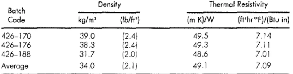
41.0 (m K)/W or 5.9 (ft2hr°F)/(Btu in).Another HCFC-141b based wall-type sprayed polyurethane foam is shown in Table 4. Four, 10 mm thick slices (426-199) were tested and the ratio of 72 day thermal resistivity to the initial value was found to be 0. 79. Thus, the long-term thermal resistivity of this foam is calculated as 0. 79 X 49.1
=
38.9 (m K)/W or 5.6 (ft2hr°F)/(Btu in).Table 3. Initial thermal resistivity of sprayed polyurethane product R (HCFC-141b).
Botch Density Thermal Resistivity
Code kg/m3 (lb/lt') (m K)/W {Imperial)
426-101 37.0 [2.3) 52.6 7.59
426-107 38.7 (2.4) 52.9 7.64
426-117 34.2 (2.1). 55.0 7.94
290 MARK 80MBERG AND KUMAR KUMARAN
Table 4. Initial thermal resistivity of sprayed polyurethane product K
(HCFC-141b).
Batch Density Thermal Resistivity
Code kg/m3 (lb/ft') (m K)/W (ft'hr°F)/(Btu in)
426-170 39.0 (2.4) 49.5 7.14
426-176 38.3 (2.4) 49.3 7. II
426-188 31.7 (2.0) 48.6 7.01
Average 34.0 (2. I) 49. I 7.09
DISCUSSION
One may compare initial thermal resistivity ofCFC-11 blown spray foam product C (Table 2) with that ofHCFC-141b blown foam products (Tables 1, 3 and 4). The HCFC blown foams have 12 to 18 percent lower initial thermal resistivities than the CFC-11 blown foam used for comparisons. Yet, the difference between the LTTP values of these sprayed foam products were much smaller than the initial differences. Product R (Table 3) showed LTTP highest of the three HCFC blown products. It was only 4 percent lower than that of the CFC-11 blown foam. The lowest long-term thermal resistivity, shown by product K (Table 4) was 9 percent lower than that of the CFC-11 blown foam. The difference of five percent highlights impor-tance of foam optimization with regard to its long-term thermal
perfor-mance.
One may also examine the effect of density on the long-term thermal per-formance. Traditionally a higher density roofing foam would be expected to have thermal performance better than a lower density wall-type foam. Prod-uct M was a roof-type foam while prodProd-uct K was a wall-type foam. Yet, the wall-type foam (product R, Table 3) had the long-term thermal resistivity equal to 41.0 (m K)/W or 5.9 (ft'hr°F)/(Btu in) that is better than roof-type foam (product M, Table 1) with the long-term thermal resistivity equal to 39.9 (m K)/W or 5.8 (ft'hr°F)/(Btu in). One may observe that the improve-ment of the cellular structure which can be obtained in the process of foam system optimization with regard to its long-term thermal performance ap-pears more important than differences in the foam density.
CONCLUSIONS
It was shown in the SPI/NRC research [3] that HCFC-141b blown foam can be optimized to have long-term thermal performance identical to a CFC blown foam. While the SPI/NRC project examined performance of a generic
Testing Long-Term Thermal Resistance of Sprayed Polyurethane Foam 29:1
sprayed polyurethane foam system and showed a potential for improvement · of sprayed foam systems manufactured with alternative blowing agents, this research examined commercially available foam systems, three blown with H141b and one manufactured for comparative purposes with CFC-11. The importance of foam optimization with regard to long-term thermal
performance was once more demonstrated.
It is apparent that polyurethane contractors must demand LTTP data from system houses to ensure that each sprayed foam system was adequately op-timized with regard to its long-term thermal performance.
REFERENCES
1. Bombcrg, M. 1993. "Factors Affecting the Field Performance of Spray Applied
Thermal Insulating Foams;' The Society of the Plastics Industry, Inc., Polyurethane Foam Contractors Division, Washington, D.C., pp. 29-77. 2. Willingham, R. 1991. "Polyurethane Foam Seminar;' Construction Canada
(March):33-34.
3. Bomberg, M. T. and M. K. Kumaran. 1989. "Report on Sprayed Polyurethane
Foam with Alternative Blowing Agents;' CFCs atld the Polyurethane Industry:
Volume 2, A Compilation of Technical Publications, SPI, pp. 1 12-128.
4. Bomberg, M. T., M. K. Kumaran, M. R. Ascough and R. G. Sylvester. 1991.
"Effect ofTime and Temperature on R-Value ofRigid Polyurethane Foams,"]. of
Thermal Insulation, 14:343-358.
5. Alumbaugh, R L 1993. "Field Performance of Spray Applied Thermal
in-sulating Foams;' The Soc. of the Plastics [ndustry, Inc., Polyurethane Foam Contractors Division. Washington, D.C., pp. 29-77.
6. 1993. "Standard Criteria for Sampling and Acceptance of Preformed Thermal
Insulation Lots;' Annual Book
if
ASTM Standards, Vol. 04.06.7. Smith, T. L. 1993. "Understanding Life-Cycle Costing," NRCA Professional
Roofing (October):66.
8. Bomberg, M. T. 1988. "A Model of Aging of Gas-Filled Cellular Plastics;'
jour-nal of Cellular Plastics, 24(4):327-347.
9. Kumaran, M. K. and M. T. Bomberg. 1990. "Thermal Performance of Sprayed
Polyurethane Foam Insulation with Alternative Blowing Agents," Journal of Thermal Insulation, 14:43-58.
10. Kabayama, M. 1987. "Long-Thrm Thermal Resistance Values of Cellular Plastic
Insulators,"] of Thermal Insulation, 10:286-300.
11. isberg,J. 1988. "The Thermal Conductivity of Polyurethane Foams," Chalmers
U of Technology, Gothenburg, Sweden.
12. Bamberg, M. T. 1990. "Scaling Factors in Aging of Gas-Filled Cellular Plastics;'