HAL Id: tel-00545697
https://tel.archives-ouvertes.fr/tel-00545697
Submitted on 11 Dec 2010HAL is a multi-disciplinary open access archive for the deposit and dissemination of sci-entific research documents, whether they are pub-lished or not. The documents may come from teaching and research institutions in France or abroad, or from public or private research centers.
L’archive ouverte pluridisciplinaire HAL, est destinée au dépôt et à la diffusion de documents scientifiques de niveau recherche, publiés ou non, émanant des établissements d’enseignement et de recherche français ou étrangers, des laboratoires publics ou privés.
Study of corrosion mechanism of new zircaloys
Haixia Zhang
To cite this version:
Haixia Zhang. Study of corrosion mechanism of new zircaloys. Material chemistry. Université Joseph-Fourier - Grenoble I, 2009. English. �tel-00545697�
Université de Grenoble – Grenoble
Xi’an Jiaotong University – Xi’an
PhD Thesis
To be graduate of
Docteur de l’Université de Grenoble, Spécialité Physique des Matériaux &
Doctor of the Xi’an Jiaotong University
Presented by
ZHANG Haixia
Study of corrosion mechanism of new zircaloys
Xi’an, November 20th 2009
Jury :
LI Zhongkui Research Director at NIN Reporter
CHATEIGNER Daniel Professor at ENSICAEN Reporter
SUN Jun Dean, Professor at Xi’an Jiaotong University Examinator XUE Xiangyi Professor, Head of «SuperCrystal Lab.» Examinator
ORTEGA Luc Researcher at Néel Institut Examinator
ZHOU Lian Professor at NPU, Doctor Honoris Causa UJF Supervisor FRUCHART Daniel Research Director at Néel Institut Supervisor
HLIL El Kébir Assistant Professor at UJF Supervisor
PhD thesis prepared at the Institut Néel, CNRS Grenoble, France
and at the Northwestern Institut for Non-ferrous Metal Research, Xi’an, China in the framework of the French-Chinese International Associated Laboratory LAS2M.
5
Thanks
The present thesis was prepared both at Nortwestern Institute for Non Ferrous Metals, Xi‘an (China) and at Institute Néel, CNRS, Grenoble (France) under the frame of the International Laboratory (LIA) LAS2M founded by the CNRS and the Chinese Academy of Sciences, gathering the two Institutes.
Thanks are due to Ambassy of France in Beijing which has granted all stays I made in Grenoble, France, so allowing the successful preparation of the thesis work.
The thesis is placed under the co-tutelle of the North-Western Polytechnic University (NPU) Xi‘an China and the Université de Grenoble, France.
Thanks are due to Mr ZHOU Lian, Professor at NPU, Doctor Honoris Causa UJF, Chinese supervisor of the thesis, to Mr HLIL El Kébir, Assistant Professor at UJF, and Mr FRUCHART Daniel Research Director at Néel Institut, both French supervisors of the thesis.
Thanks are due to the members of the Jury who have accepted to report the thesis work: Mr LI Zhongkui, Research Director at NIN (China) and Mr CHATEIGNER Daniel, Professor at ENSICAEN (France).
Thanks are due to the members of the Jury who have accepted to evaluate the thesis work: Mr SUN Jun, Dean, Professor at University Jiaotong Xi‘, Mr XUE Xiangyi, Professor, Head of «Super Crystal-Lab», Mr ORTEGA Luc, Researcher at Néel Institut.
Thanks are due to all my colleagues at NIN, NPU, CNRS who have help, encouraged and support me, day by day, for the best achievement of the present work.
7
Outline
Chapter 1 p. 9
1 Introduction p. 11
1.1 Development of nuclear power p. 11
1.2 The nuclear reactor and fuel cladding p. 11 1.3 The main problem of zirconium alloys cladding p. 13 1.4 The purpose, significance and content of this research p. 14
Chapter 2 p. 15
2 Research summary on the corrosion resistance of zirconium alloys p. 17 2.1 Brief introduction of zirconium allos used in nuclear reactor p. 17 2.2 Research summary of the waterside corrosion of zirconium alloys p. 19 2.3 The oxidation of zirconium alloys p. 21 1.4 Research summary of out-pile corrosion of zirconium alloys p. 23
Chapter 3 p. 25
3 Research methods p. 27
3.1 The materials used in the experiments p. 27
3.2 The autoclave experiment p. 27
3.3 Analysis and measurements p. 29
Chapter 4 p. 31
4 Corrosion resistance of zirconium alloys p. 33
4.1 Introduction p. 33
4.2 Corrosion resistance of zirconium alloys in LiOH water p. 34 4.3. Corrosion resistance of zirconium alloys in 400°C steam p. 34 4.4 Corrosion kinetics of zirconium alloys with low Nb content in different media p. 35
4 5 Summary p. 35
Chapter 5 p. 37
5 Relationship of the matrix microstructure and corrosion resistance of new zirconium
alloys p. 39
5.1 The matrix microstructure of zirconium alloys p. 39 5.2 Matrix microstructure effect on the corrosion resistance of zirconium alloys p. 41
5.3 Summary of the chapter p. 43
Chapter 6 p. 45
6 The oxide film crystal structure effect on the corrosion resistance p. 47
6.1 Introduction p. 47
6.2 The crystal structure of NZ2 alloy oxide films p. 47 6.3 The crystal structure of NZ8 alloy oxide films p. 59
8
Chapter 7 p. 65
7 Relationship between residual stresses, crystal structure of oxide films and corrosion
resistance p. 67
7.1 Introduction p. 67
7.2 Principles p. 67
7.3 Experimental methods p. 69
7.4 Experimental conditions and data processing p. 71
7.5 Experimental results p. 71
7.6 Analysis and discussion p. 71
7.7 Summary of the chapter p. 75
Chapter 8 p. 77
8 Investigation of corrosion mechanisms of new zirconium alloys containing niobium
p. 79 8.1 The stabilisation mechanisms of t-ZrO2 and c-ZrO2 p. 79
8.2 The stress release mechanisms in the oxide films p. 82 8.3 The corrosion mechanisms of new zirconium alloys p. 83
Chapter 9 p. 87
9 Main conclusions p. 89
9
Chapter 1
11
Chapter 1 Introduction
1.1 The development of nuclear power
The nuclear industry is the important application field of zirconium and zirconium alloys. The metallurgy industry of zirconium and zirconium alloys develops with the exploitation and using of nuclear energy.
The nuclear energy age commences with the discovering of the nuclear fission and the development of nuclear reactor pile realizes the using of the nuclear energy. The characteristic of nuclear energy is its high energy density. The using of nuclear energy can greatly decrease the exploitation of fossil fuel, thus alleviate the energy crisis. In addition, the nuclear power plants don‘t release CO2, SO2 and NOx, so this can lighten the environment pollution and
decrease the harm of global calefaction. Also the accident probability of nuclear power plant is very low [1,2]. Therefore, the nuclear power is a kind of high efficient, economical, safe and cleanly energy, and the final energy requirement of the human will depend on the nuclear energy.
The first test nuclear power plant was found in Soviet Russia in 1954 and the first commercial nuclear power plant was found in America in 1957. Nuclear industry has developed for more than half one of century, and the loading capability and the ability of furnishing power are enhancing steadily. At the end of 2004, there were 440 nuclear power plants in the whole world, 104 in American, 59 in France, 53 in Japan. The amount of nuclear generating electricity was 16% in the world [3].
In China, the nuclear power development started at the middle time of 1980‘s, but the design work started at 1970‘s. The first nuclear power plant (Qinshan nuclear power plant) was built in 1985. Its favoring run finished the nonnuclear power history of China. At present, there are 3 nuclear power plants in China: Qinshan nuclear power plant in Zhejiang province, Dayawan nuclear power plant in Guangdong province and Tianwan nuclear power plant in Jiangsu province. Another two new nuclear power plants are planning: Sanmen nuclear power plant in Zhejiang province and Yangjiang nuclear power plant in Guangdong province. The loading capability in China is 8.7 GW and the amount of furnishing power is 2.3%. China government proposed that the nuclear power should be developed greatly and the loading capability would reach 40 GW in 2020[4]. So the decrease of nuclear power cost will promote its great development. The best measure decreasing the nuclear power cost is to heighten fuel consume, prolong the changing fuel period. Thus the security and reliability of reactor pile are required, and the using problems of key materials in nuclear reactor pile are greatly noticed.
1.2 The nuclear reactor and fuel cladding
The reactor piles used at best are PWR. It is a thermal neutron reactor pile whose once cooling water is under the boil pressure (14~16 MPa). PWR reactor piles occupy 67.5% of the gross of nuclear power piles and 74.1% of the total power[1,5]. Because PWR has many advantages: 1) Mature technique and high security; 2) Low investment.
The reactor pile is the reaction equipment that can do fission reaction by controllable method. Fig. 1-1 is structural scheme of PWR. It
consists of pile core, reflected shell, control club, pile container and shield shell et al. The fuel subassembly is collected in the pile core, which consists of fuel core, cladding and port plug et al. Nuclear fuel core is the matter that arises the fission reaction in the reactor pile. The fuel core is packed in the cladding and becomes fuel assembly (Fig. 1-2). So the fuel assembly is the most important components in the reactor pile. It decides the security and economy of the reactor pile. However the using life of fuel assembly is close related to the properties of
12
cladding materials. The actions of cladding include: 1) Separating the fuel core and cooling water, preventing the chemical reaction between the fuel core and cooling water; 2) Stopping the transgression of fission productions, preventing the pollution of matter with radioactivity. It‘s the first safe barrier of the reactor pile; 3) Transferring the heat energy caused by the fission of fuel core to the refrigerant, and providing enough structure strength to make the fuel components remain the integrity of structure and the steady of size. Therefore, the cladding material is a kind of key material preparing the nuclear fuel components.
13
Fig. 1.2 The fuel assembly of PWR
1.3 The main problems of zirconium alloys cladding
Due to the small thermal neutron absorption section, good corrosion resistance in high temperature and pressure water and good high temperature strength et al, zirconium alloy is the only cladding material in the water-cooling nuclear reactor pile at present.
When the reactor pile runs, the cladding material works in the high temperature and pressure water and is corroded to ZrO2, at the same time, Hydrogen is released. On the one
hand, the cladding thickness reduces by the corrosion, thus the using life of fuel components is shortened; On the other hand, a part of hydrogen released by the corrosion reaction is absorbed by zirconium alloy, other hydrogen will precipitate to form hydride which makes zirconium alloys brittle [6,7]. There are many studies about the hydrogen weight gain performance [8-11]. The corrosion and hydrogen pickup are two important problems in the using of zirconium alloys. To reduce the nuclear power cost, the fuel consume has to be heightened. Thus how to improve the corrosion resistance of cladding material and reduce hydrogen pickup should be further studied.
14
1.4 The purpose, significance and content of this research
In general, after the corrosion resistance of zirconium alloys is improved, the corresponding hydrogen pickup is reduced. So the corrosion resistance of zirconium alloys is an important aspect exploiting new alloys. It is good for the choice of the alloying elements and adjusting of the heating treatment techniques to study the effects of alloying composition, precipitate, oxide crystal structure and stress distribution et al on the corrosion behaviours.
In this thesis, several aspects as follows are studied:
(1) Studying the effect of matrix microstructure (alloying element composition, the category and distribution of the precipitates) on the corrosion behaviours of zirconium alloys;
(2) Studying the effect of oxide crystal structure (phase transformation and stress distribution) on the corrosion behaviours of zirconium alloys;
(3) Doing the above studies using two kinds of water chemical conditions.
The three aspect studies are not isolated, and they are interdependent. Understanding the microstructure effect on the corrosion behaviour, this can provide the foundation to choose alloying elements while developing the new zirconium alloys; It is good to improve corrosion resistance and explore the corrosion mechanism t study the relation of oxide crystal structure and corrosion behaviours.
There are 9 chapters in this thesis.
Chapter 1 introduces the nuclear power development, main problems of zirconium alloys cladding in reactor pile and purpose, significance and content of this research.
Chapter 2 introduces the research summary of the corrosion resistance of zirconium alloys. Chapter 3 introduces the study methods, including material, experimental conditions, equipments and the analysis methods et al.
Chapter 4 introduces corrosion kinetics of new zirconium alloys in different mediums.
Chapter 5 studies the effects of microstructure, including alloying element composition, precipitates, on corrosion resistance.
Chapter 6 studies how to the oxide structure change affect the corrosion resistance.
Chapter 7 is about the study of stress state in the oxide film; Chapter 8 discusses the corrosion resistance of new zirconium alloys.
15
Chapter 2
Research summary
of the corrosion resistance
of zirconium alloys
17
Chapter 2 Research summary of the corrosion resistance
of zirconium alloys
2.1 Brief introduction on zirconium alloys used in nuclear reactor
2.1.1 Basic characteristics of zirconium
Pure zirconium crystal is hcp structure at room temperature, and the c/a is 1.593. The crystal lattice constant is a=0.323 nm, c=0.515 nm [12]. At 865oC pure zirconium has an allotropic transformation from α hcp phase to β bcc phase. While cooling zirconium has martensite phase transform. The α-phase formed in sheet β crystal. The melting point of zirconium is 1860oC. The main physical properties of zirconium are given in Tab. 2-1.
Tab. 2-1 Physical properties of Zr[13] Unit Mean value [11-20] direction [0001] direction Density Kg m-3 6.500 Coefficient of heat expand K-1 6.7×10⁻⁶ 5.2×10⁻⁶ 10.4×10⁻⁶ Young modulus GPa 99 125 Lattice constant nm a = 0.323 c = 0.515 Heat conduction W m-1 K-1 22 Specific heat J kg-1 K-1 276 Thermal neutron seizing section barn (10-28m2) 0.185
2.1.2 Zirconium alloys used in nuclear reactor
Due to the low heat neutron absorption section, zirconium alloys are used as nuclear fuel cladding. Thus good corrosion resistance and mechanics properties are gained. To remain the property of low heat neutron absorption section, element composition with high heat neutron absorption section should be very low[14]. Now main zirconium alloys include Zr-Sn, Zr-Nb and Zr-Sn-Nb three systems
1. Zr-Sn system alloys [15,16]
The corrosion resistance of pure zirconium is good. But the impurity elements caused by the metallurgy process, N, C, Ti, Al, Si et al, weaken the corrosion resistance. Sn is the element stabilizing α and can form substitute solid solution in α and β phases. So it can counteract the deleterious action of N in zirconium. The initial zirconium alloy was Zr-Sn alloy, the composition is Zr-2.5Sn, called Zr-1 alloy. But the corrosion resistance of Zr-1 alloy is too bad to be used. Later Zr-2 alloy was developed. Ni is main element causing to the high hydrogen weight gain of Zr-2 alloy. So Ni was removed from Zr-2 alloy and Fe was
18
increased to get Zr-4 alloy. Zr-2 and Zr-4 alloys have been used commercially. Zr-2 is used to the cladding material in BWR, and Zr-4 is used in PWR. They belong to Zr-Sn system, called the first zirconium cladding material.
With the improvement of metallurgy technique, N can be controlled at lower level. Because it is not good for the improvement of corrosion resistance to increase Sn content, Zr-4 composition is optimized: adjusting Sn content to lower limit (1.2 ~ 1.5 Sn), Fe and Cr contents to upper limits (Fe ~ 0.24, Cr ~ 0.13). This is improved Zr-4 alloy. Its corrosion resistance is better than the normal Zr-4 alloy and has been used widely. This is called the second cladding material.
2. Zr-Nb sytem alloys
When American and some west counties tried to develop Zr-Sn system alloys, Soviet Russia developed another series of alloys, Zr-Nb alloys. The merits of Nb are low thermal neutron absorption section. Nb can eliminate the harm of C, Al, Ti et al to corrosion resistance and reduce the hydrogen pickup. At present, E110 alloys of Russian, M5 of France, Zr-2.5Nb alloys are commercially used [19-21]. Zr-2.5Nb is specially used in CANDU pile. Zr-2.5Nb-0.5Cu alloy is exploited to gain higher strength material [14,22].
The corrosion resistance of Zr-Nb alloys is sensitive to the processing and heat treatment. Small and well-distributed β-Nb precipitates are good, however the β-Zr is not good [25].
3. Zr-Sn-Nb system alloys
Zr-Sn-Nb system alloys integrates the merits of Zr-Sn alloys and Zr-Nb alloys to meet the need of high fuel consume. ZIRLO alloys of American, E635 alloys of Russian, NDA alloys of Japan, HANA alloys of Korea , NZ2 and NZ8 alloys of China [26-47], the in-pile corrosion resistance of above alloys is better than that of Zr-4. At present, NZ2 alloys in China have been used in in-pile testing.
The development of nuclear energy is gradually promoting the research work of zirconium. Tab. 2-2 shows some main alloys used and studied.
19
Tab. 2-2 Main zirconium alloys in nuclear industry
Name Composition Country Remark
Zr-2 Zr-1.5Sn-0.2Fe-0.1Cr-0.05Ni American Using Zr-4 Zr-1.5Sn-0.2Fe-0.1Cr American Using Zr-2.5Nb Zr-2.5Nb Canada Using
Zr-1Nb Zr-1Nb Soviet Union Using ZIRLO
Zr-1.0Sn-1.0Nb-0.1Fe
American Using
M5 Zr-1.0Nb-0.16O France Using
E635 Zr-1.2Sn-1.0Nb-0.4Fe Russia Using NDA Zr-1.0Sn-1.0Nb-0.4Fe Japan Studying NZ2 Zr-1.0Sn-0.1Nb- 0.28Fe-0.16Cr-0.01Ni China Studying NZ8 Zr-1.0Sn-1.0Nb-0.3Fe China Studying HANA6 Zr-1.1Nb-0.05Cu Korea Studying HANA3 Zr-1.5Nb-0.4Sn-0.1Fe-0.1Cu Korea Studying HANA4 Zr-1.5Nb-0.4Sn-0.2Fe-0.1Cr Korea Studying
2.2 Research summary of the waterside corrosion of zirconium alloys
2.2.1 Water chemical effect on corrosion behaviour
Now more than 90% commercial nuclear power plants are light water reactor plants, others are heavy water plants. Because zirconium alloys have good corrosion resistance, mechanics property and high heat exchange property, the fuel component cladding or the pressure tube material is made of zirconium alloys [14]. When the nuclear plant of light water pile runs, the internal side of zirconium alloy cladding contacts with the fission products at 400oC, and the external surface contacts with high temperature and high pressure water (280~350oC,10~16 MPa). Generally H3BO3 and LiOH are added to cooling water to
adjust the pH value.
The corrosion resistance of zirconium alloys are an important index deciding its using properties in nuclear power plant. During the study on the corrosion behaviour, the out-pile autoclave experiments are carried out to simulate the in-pile situation. For the same alloy, the transition time and the post-transition corrosion rate in different mediums are different. And the sensitivity of the same alloy to different water chemical conditions are different [48].
20 2.2.2 Alloys composition effect on corrosion behaviour
To get the zirconium alloys with better corrosion resistance, many researches about the alloying element effect on the corrosion resistance have been done [15,38,43,49-59]. The alloying element effects are very complicated, associating to the kind of alloying element, ratio and water chemical condition. In general, low Sn content, high Fe content, the additions of a little Nb and Cu, can improve the corrosion resistance of zirconium alloys. However, Mo is harm and the function of V is not clear. For Zr-Sn alloys, Nb content should not be too high, and a little Cu addition can further improve the corrosion resistance; For Zr-Sn-Nb alloys, decreasing Sn and Nb contents can further improve the corrosion resistance.
To implode the zirconium with high properties, it is necessary to establish a clear relation between alloying element and corrosion resistance, understand really the alloying element effect on the corrosion resistance.
2.2.3 Heat treatment effect on the microstructure and corrosion behaviour of the alloys
Alloying composition and heat treatment decide the microstructure of the alloy, moreover the microstructure decides the corrosion resistance and the mechanics property. In the case of certain alloying composition, appropriate heat treatment can further improve the corrosion resistance.
In Zr-2 and Zr-4 alloys, the solid solutions of alloying elements Sn, Fe, Cr, Ni are high in β-Zr, however those are low in α-Zr [23]. Most alloying elements exist in the precipitates. The heat treatment in α phase region after β quenching can affect the precipitate size and distribution. So Steinberg [60] introduced the accumulative annealing parameter A, and studied the relation between A value and corrosion resistance of Zr-2, Zr-4 alloys [53,61-66]. The results shown that 2×10-18h ≤ A ≤ 5×10-17h was good for even corrosion resistance and A ≤ 10-18h was good for nodular corrosion resistance.
Garzarolli and Foster [62,65,67] thought that the precipitate size, amount and distribution were changed by the A value change. When the size of precipitate was small (~50 nm), the corrosion resistances of Zr-2 and Zr-4 in 420oC steam and 360oC water were bad, but the nodular corrosion resistances in 500 oC steam were good. That‘s contrary when the size of precipitate was more than 200 nm. So they thought that the effect of heat treatment on the corrosion resistance was related to the precipitate size and amount changed by the heat treatment.
Zhou [68,69] found that there was no the above corresponding relation between the heat treatment and corrosion resistance. They thought that the alloying element content change in the matrix caused by the heat treatment was main reason of corrosion resistance change.
It‘s obvious that there is no consistent understand in the effect reason of heat treatment on corrosion resistance of Zr-2 and Zr-4 alloys. This should be studied further.
The microstructure of zirconium alloys containing Nb is more complicated than that of Zr-4 alloys. The accumulative annealing parameter A is not applicable to zirconium alloys containing Nb[70].
Many studies approved [25,71-78] that the corrosion resistance of zirconium alloys with low Nb (< 0.6%) was not sensitive to heat treatment, however that of zirconium alloys with high Nb (> 0.6%) was sensitive. β-Zr and supersaturated Nb in the matrix are harm to the corrosion resistance. The corrosion resistance of zirconium alloys containing Nb is related to the changes of the supersaturated Nb content and precipitates during heat treatment. The mechanism of heat treatment effect on corrosion resistance of zirconium alloys containing Nb is not understood clearly.
21
2.3 The oxidation of zirconium alloys
The growth kinetics of oxide is obtained by the weight gain kinetics. This supposes that the oxide is remained on the sample and the oxide is even. The oxide thickness is obtained by the conversion of ZrO2 density. 1μm thickness oxide is equal to 15 mg/dm2 weight gain.
Corrosion kinetics of different zirconium alloys can be compared by this method. 2.3.1 The oxidation kinetics of even corrosion of zirconium alloys
The weight gain kinetics of zirconium alloys is divided to two stages: pre-transition and post-transition [12,84,85]. The pre-transition characteristic is low weight gain rate, similar to cubic curve, not parabola curve expected by Wagner-Hauffe theory. Because the oxide growth controlled by diffusion happens at the crystal boundary, not in the even solid [86-88].
Many studied about the stress, texture and crystal structure of oxide film have been done [89-93]. At the beginning of corrosion, the oxide formed on the surface of metal is t-ZrO2.
The corrosion transition happens when the oxide film thickness reaches 2~3 μm, and the corrosion rate is similar linear [12,84,85]. The linear rate increases with the thickness increasing [94]. The transition process is a mark of the formation of holes in the oxide film
[83-97]
.
The corrosion kinetics of Zr-Sn alloys and Zr-Nb alloys are different. There is no clear rate transition in the kinetics of Zr-Nb alloys, and the change from cubic to linear is not observed [98-100].
2.3.2 The oxidation process
First the zirconium alloys with fresh surface will take an oxidation reaction: Zr+2H2O→ZrO2+2H2. The beginning reaction is slow and a thin, protective oxide film is
formed, which further prevents the oxidation. The dense oxide consists of t-ZrO2, which
stable at high temperature. Subsequently O2- in the oxide film dissolves to metal to form anion vacancies. O2- diffuses from the oxide film surface and passes the oxide by vacancy mechanism to react with Zr. While the oxide growing, stresses are produced by the volume expander. The compressive stresses can‘t be counteracted by the tensile stresses in the metal, thus the martensite phase transformation happens and the m-ZrO2 is formed, the film becomes
loose. During the process, many small holes and cracks are formed and the corrosion is accelerated [101-103].
2.3.3 The growth theory of oxide film
Wagner theory thought that O2- diffuse along the anion vacancies of oxide film and passes the oxide film to metal surface, moreover the electrons moves from the metal surface to outside, thus the oxide film grows at the metal/oxide interface. Their balance rate or the substitute rate of O2- and the vacancies in the oxide film decides the corrosion rate [103]. Another theory supports O2- diffusing through the crystal boundaries [105,106].
2.3.4 Corrosion mechanism
The oxide structure change leads to many cracks and holes, thus the oxide film becomes loose and loses protect. The corrosion rate increases, even the oxide film scales off [102].
22 1. Diffusion hypothesis
After Li+ enters the oxide film, the concentration of anion vacancy increases, which accelerates the vacancy diffusion and corrosion. There is another hypothesis, namely the re-crystallisation process is changed by Li+ in-break, which thins the crystal and increases crystal boundaries. The short circuit diffuse channels of the anion vacancies are increased and the vacancy diffusion is accelerated [102,108].
2. Dissolving hypothesis of Cox [109]
Because c-ZrO2 or t-ZrO2 is preferential dissolved in LiOH to m- t-ZrO2, thus big holes
appear. These holes accelerate the corrosion rate. 3. OLi group cumbering hypothesis
Ramasubramanian [110] thought a majority of Li were absorbed in the holes of the oxide film, and the undecomposed LiOH would react with the anion vacancies on the surface of oxide film to form OLi group. The OLi moved to ZrO2 crystal boundary to prevent the crystal
growth and thin the crystal, increase the diffuse passages of anions. 4. Barrier hypothesis
Pecheur [111] proposed that there was a dense barrier at the metal/oxide interface. The thickness of this barrier increases gradually at the corrosion pre-transition until about 1μm, and the thickness decreases to 0.1μm after the transition happens. So he thought the addition of LiOH could destroy the barrier to accelerate the corrosion.
5. Phase transformation hypothesis [112]
LiOH can decrease the compressive stresses in the oxide film and lead to the transformation from t-ZrO2 to m-ZrO2, even the t-ZrO2 is not formed.
2.3.5 The crystal structure of oxide film [102,113]
In inner oxide film, t-ZrO2, c-ZrO2, m-ZrO2 exist. In the middle layer of oxide,
vacancies et al diffuse and agglomerate and the internal stresses in the oxide film release. Sub-stable phases transform to stable m-ZrO2 and small holes form at the crystal boundary.
The holes develop to cracks. On the oxide surface, the holes are big, so the oxide on surface is m-ZrO2 [113].
2.3.6 Oxidation of the precipitates [102]
The precipitates are incorporated into the oxide film and oxidized at a certain distance from interface. During the oxidation, the metal atoms in the precipitates will release to the metal matrix. Fe is oxidized when t-ZrO2 transforms to m-ZrO2. Some precipitates become
non-crystalline in the oxide film. And the precipitates have a function of short circuit, this could be the starting position of nodular corrosion.
23
2.4 Research summary of out-pile corrosion of zirconium alloys
Now, the studies about the relationships of processing techniques, microstructure characteristic and out-pile corrosion resistance, have been done widely. The processing techniques and microstructure characteristics belong to metallurgy factors. Although the corrosion mechanism has been studied for more than half one century, there is no clear understanding for the corrosion mechanisms of mature alloys (Zr-2, Zr-4, Zr-1Nb et al). So the studies for the corrosion mechanism of the third zirconium alloy should be done deeply.
25
Chapter 3
27
Chapter 3 : Research methods
NZ2 and NZ8 alloys, submitted to a certain heat treatment, are chosen to study the corrosion behaviours in different mediums. The effects of Nb addition and oxide microstructure on the corrosion resistance are understood by studying the corrosion weight gain, microstructure change of matrix, crystal structure of oxide film, phase content and stress in the oxide film.
3.1 The materials used in the experiments
The experimental samples are 1mm plates from NIN. The element compositions of two alloys and Zr-4 alloy (used to compare) are shown in Tab. 3-1. Zr-4 alloy belongs to Zr-Sn system and is used widely now. NZ2 and NZ8 belong to Zr-Sn-Nb system and is in the stage of studying and exploitation.
The plates are gained by following techniques flow:
Three vacuum melting-β forging-β quenching-α hot rolling (<600oC)-three intermediate annealing and the 30-50% cold process after every annealing-plates (δ=1mm) and final recrystal annealing (580oC/2h). The intermediate annealing parameters are shown in Tab. 3-2.
Tab. 3-1 The element compositions of two alloys (wt.%) Alloys Sn Nb Fe Cr O Zr
Zr-4 1.5 - 0.2 0.1 Balance NZ2 1.0 0.3 0.3 0.1 0.08-0.14 Balance NZ8 1.0 1.0 0.3 - 0.08-0.14 Balance
Tab. 3-2 The intermediate annealing parameters
First time annealing Second time annealing Third time annealing 650ºC/2h 590ºC/2h 590ºC/3h
3.2 The autoclave experiment
The corrosion resistance of zirconium alloys to high temperature water is an important property of nuclear fuel cladding. The out-pile autoclave corrosion experiment, simulating nuclear reactor pile conditions, is a usual method of studying the corrosion behaviours. The samples are corrosion tested simultaneously in single autoclaves with test being periodically interrupted to measure specimen weight gain. Corrosion weight gain is the average value of four samples. Corrosion kinetics is determined by measuring the weight gain as a function of exposure time.
28 3.2.1 Corrosion conditions
Long-term corrosion testing of plates specimens (15mm×25mm×1mm) was performed in static autoclaves at 360oC/18.6MPa pure water, 360oC/18.6MPa lithiated water and 400
o
C/10.3MPa steam. Then the samples corroded for different time were tested. 3.2.2 The instruments used in the autoclave corrosion testing
1. Autoclave: A special autoclave, cubage is 2L, compression resistance is 30MPa, and pressure meter, drain tap and the slice preventing blast are equipped.
2. Instrument controlling temperature: controllable Si electric cooker instrument controlling temperature, the controlling precision is ±1oC.
3. Weighing up: the high precision balance is used, the precision is 0.01mg. 4. Testing the sample size: vernier calliper is used, the precision is 0.2mm. 3.2.3 The method indicating the corrosion degree
In this study, multiple specimens are tested simultaneously in single autoclaves with test being periodically interrupted to measure specimen weight gain. Corrosion kinetics is determined by measuring the weight gain as a function of exposure time. The corrosion weight gain is indicated by the method of measuring the weight gain of unit area. The formula is wt=1000•(Wt-W0)/S, W0 is the weight of sample uncorroded (mg), Wt is the weight of
sample corroded (mg), S is the area of sample (mm2), wt is the weight gain (mg/dm2).
3.2.4 Preparation of samples in the autoclave experiments 1. Cutting the samples to 25×15 mm pieces.
2. Doing marks on the samples and drilling φ1.5mm holes on the samples.
3. Dipping the samples in acetone and cleaning the smarminess of the sample surface with the absorbent cotton.
4. Putting the samples in the acid to clean, the cleaning temperature is 30~50o; 10%HF+45%HNO3+45%H2O is used to clean zirconium alloys containing Nb, and
10%HF+30%HNO3+30%H2SO4+45%H2O is used to clean zirconium alloys not containing
Nb.
5. Immediately putting the samples to flowing water for at least 15 min. 6. Putting the samples to boiling water to clean at least thrice.
7. Drying the samples.
8. Weighing in by the electronic balance, the precision is 0.01 mg. 9. Measuring the size by vernier calliper.
29
3.3 Analysis and measurement
3.3.1 The measurement of microstructure and precipitates of the alloy samples
JEM-200CX transmission electron microscope is used to test the microstructure and the precipitates. The processing of specimen preparation is as following: thinning the specimen to 70~80 μm by machine method, then preparing φ3 mm wafer with special tool and preparing thin specimens by electrolyse polishing. EDS is used to analyze the compositions of the precipitates.
3.3.2 The measurement of crystal structure and internal stresses in the oxide film
To study the corrosion mechanism of new zirconium alloys containing Nb, a large panel of normal methods were used in this study.
1. X-ray diffraction instrument
The phase structure of material could be confirmed by analyze the peak position and intensity of X-ray diffraction; The internal stresses in the oxide film could be confirmed by the peak shift of m-ZrO2. The grazing XRD instrument of PW3830 (Fe, λKα = 1.93637
Å)was used to test the surface structure of oxide film. The normal XRD instrument of PW3830 (Cu, λKα = 1.544426 Å)was used to test the structure of the whole oxide film and
internal stresses.
2. A JY-T64000 laser Raman spectrometer in the Institute of Physics, Chinese Academy of Sciences was used to test the crystal structure of different thickness of oxide film in order to confirm the phase transformation during corrosion.
3. Neutron diffraction instrument
D1B neutron diffraction instrument of ILL in France was used to test the category and structure of precipitate.
4. Scanning electron microscope
JSM-840A scanning electron microscope of CNRS in France was used to analyze the oxide film section.
3.4 Processing of datas
Photoshop software was used to deal with the photos, XRD and Raman datas were plots by Origin software, and the data about stress analysis was dealed with by Igor software.
31
Chapter 4
33
Chapter 4 Corrosion resistance of zirconium alloys
4.1 Introduction
The waterside corrosion resistance of zirconium alloys is an important index determining if the material can be used as nuclear fuel cladding. In the investigation of the corrosion behaviour of zirconium alloys, the autoclave testing is used to out-pile simulation study. Several water chemical conditions are used in the out-pile autoclave corrosion test:
1. 350~370oC/16~19 MPa pure water, used to understand the normal corrosion regularity.
2. 350~360oC/16~19 MPa LiOH or LiOH+H3BO3 aqueous solution, used to simulate
the in-pile water chemical conditions and understand the effect of LiOH or H3BO3 on the
corrosion behaviours of zirconium alloys.
3. 400~420oC/10.3 MPa steam, used to study the even corrosion behaviours of zirconium alloys.
4. 500oC/10.3 MPa steam, used to study the study the nodular corrosion behaviours of zirconium alloys.
When zirconium alloys are corroded in the high temperature water and overheating steam, the corrosion weight increasing in divided to two stages[114]: Pre-transition and post transition stages. The pre-transition corrosion characteristic is mainly the low weight increasing rate, namely the oxide film is thin. The kinetics curve of Zr-Sn alloys is close to cube, not parabola kinetics expected by the Wagner-Hauffe theory, and the kinetics curve of Zr-Nb alloys is cube or close to parabola. When the oxide film reaches to a certain thickness, the corrosion kinetic takes a linear variation (or close to linear relation) [115-128]. As the oxide film thickness reaches to 2~3 μm and the corrosion weight increasing reaches to 30~50mg/dm2, the corrosion transition happens. Some researchers found that the post-transition kinetics curve of zirconium alloys is not simple linear relation [129-131]. So the weight curve is divided: similar parabola curve, namely pre-transition stage, gradual change stage and linear stage (Fig. 4-1) [118].
With the corrosion medium change, there are 3 kinds of kinetics transition models [132]. The first is the circle gradual change: in 300~360oC water, the transition is sudden, the post-transition corrosion rate increases rapidly and then the pre-post-transition corrosion discipline is repeated. In this study the corrosion processes of NZ2 alloys in 360oC pure water and LiOH water show the same discipline. The second is uni-directional gradual change: in higher temperature Oxygen or steam, there is no sudden kinetics transition (from cube to linear). The third is super-linear transition: the transition is from similar cube to square and then to linear. The corrosion rate does not increase during the total corrosion. In this study the corrosion processes of new zirconium alloys in 400oC steam show the same discipline.
It is generally considered that the kinetics transition indicates the hole formation in the dense oxide film [114]. The transition time is different in the different composition alloys and different corrosion medium.
It is necessary to improve the corrosion resistance of zirconium alloys to meet the needs of higher using properties. The corrosion behaviours of zirconium alloys in different mediums are studied in this chapter.
34
Fig.4-1 Oxidation kinetics in autoclave test for zirconium alloys
4.2 Corrosion resistance of zirconium alloys in LiOH water
The corrosion kinetics curves of NZ2, NZ8, improved Zr-4 alloys in 360oC/18.6 MPa LiOH water are shown in Fig. 4-2. Zr-4 alloy samples are sensitive to the corrosion in 360oC/18.6 MPa LiOH water. After the transition happens, the oxide film loses the protection and the reaction controls the corrosion process. However the corrosion resistances of NZ2 and NZ8 alloys are much better than that of Zr-4. When the new zirconium alloys are corroded for about 200 days, the weight increase is less 10% than that of Zr-4 alloys. At the beginning of corrosion, the corrosion resistances of NZ2 alloys and NZ8 alloys are similar, and the transition happens at 126 days and 98 days respectively. The corresponding oxide thicknesses at the transition points are both 2~3 μm. The post-transition corrosion rate of NZ8 alloys is higher than that of NZ2 alloys. When the alloys are corroded for more than 300 days, the weight increasing of NZ2 alloys is about 80% that of NZ8 alloys. The corrosion resistance of NZ2 alloys is the best, because of the Nb addition compared to Zr-4; Fe and Sn contents in NZ2 alloys are the same to those in NZ8 alloys, but Cr exists in NZ2 alloys and the Nb content in NZ2 alloys is lower that in NZ8. The precipitates in NZ2 alloys are cubic Zr(Fe,Cr)2 and Zr(Fe,Cr,Nb)2, and the precipitates in NZ8 alloys are β-Zr containing Nb. So
it‘s concluded that Nb addition can improve the corrosion resistance of zirconium alloys in 360oC LiOH water.
4.3 Corrosion resistance of zirconium alloys in 400oC steam
The corrosion kinetics curves of NZ2 and NZ8 alloys in 400oC/10.3 MPa steam are shown in Fig. 4-3. The pre-transition corrosion rates of both alloys are the same, and the transition time of NZ2 alloys is 42 days, that of NZ8 alloys is 70 days. The corresponding oxide thicknesses are 2~3 μm. The post-transition corrosion rate of NZ8 alloys is much higher than that of NZ2 alloys. Investigating the kinetics curve differences of zirconium alloys, we can find that the composition play an important role to improve the corrosion resistance of zirconium in 400oC/10.3 MPa steam. The large quantities of β-Zr precipitates and the supersaturated Nb content in the NZ8 matrix could be the main reason of high post-transition corrosion rate, which will be discussed in next chapter. The low Nb content in NZ2 is the main reason of its good corrosion resistance. Comparing the compositions and corrosion resistances of these alloys, it‘s difficult to conclude the alloying element effect regulation on
35
corrosion resistances of zirconium alloys in 400oC/10.3 MPa steam, but it‘s indicated that too high Nb content is not good to improve corrosion resistance. In addition, the corrosion transition time of NZ2 alloys is shorter than that of NZ8 alloys. The small precipitates in NZ2 alloys are oxidized rapidly, which shortens the pre-transition time. The oxidation of bigger precipitates in NZ8 alloys needs longer time. Thus the appropriate size of precipitate is good to improve the corrosion resistance.
4.4 Corrosion kinetics of zirconium alloys with low Nb content in different media
The corrosion kinetics curves of NZ2 alloys in 360oC/18.6MPa pure water, 360oC/18.6 MPa lithiated water, 400oC/10.3 MPa steam are shown in Fig. 4-4. The corrosion rate of NZ2 alloys increases in the sequence of 360oC/18.6 MPa pure water, 360oC/18.6 MPa lithiated water and 400oC/10.3 MPa steam, and the transition time is 182 days, 126 days and 42 days respectively. It‘s indicated that the corrosion medium plays an important role to corrosion behaviour of zirconium.
4.5 Summary
The corrosion resistance of new zirconium alloys containing Nb in 360oC lithiated water is much higher than that of Zr-4 alloys, that is to say, Nb addition is good to improve the corrosion resistance of zirconium alloys. Whatever in 360oC lithiated water or in 400oC steam, the corrosion resistance of NZ8 alloys containing high Nb is less than that of NZ2 alloys with low Nb content, which is related to the precipitate particles and alloying element content in matrix. And the oxide thickness at transition point is 2~3 μm. In addition, small, well-distributed precipitates shorten the transition time of NZ2 alloys in 400oC steam, but improve the post-transition corrosion resistance of zirconium alloys. In the different mediums, the corrosion kinetics of one alloy is different.
0 50 100 150 200 250 300 350 400 0 200 400 600 800 1000 1200 We igh t Gai n(mg/dm 2 ) Exposure time(days) NZ2-360oC Li water NZ8-360oC Li water Zr-4-360oC Li water
36 0 100 200 300 400 0 60 120 180 240 300 transition point transition point Wei ght G ai n( m g/ dm 2 ) Exposure time(days) NZ2-400oC steam NZ8-400oC steam
Fig.4-3 Corrosion kinetics of NZ2 and NZ8 alloys investigated in 400oC steam
0 50 100 150 200 250 300 350 400 10 20 30 40 50 60 70 80 90 100 110 120 130 140 150 160 Wei ght G ai n(m g/ dm 2 ) Exposure time(days) NZ2-360oC pure water NZ2-360oC Li water NZ2-400oC steam
37
Chapter 5
Relationships between
the matrix microstructure
and the corrosion resistance
39
Chapter 5 Relationships between the matrix microstructure
and the corrosion resistance of new zirconium alloys
5.1 The matrix microstructure of zirconium alloys
TEM images of NZ2 alloys matrix is shown in Fig. 5-1(a), (b). The precipitates are well-distributed and the amount of the precipitates is small, the average size is about 50 nm. The EDS analysis shows that there are two kinds of precipitates, cubic Zr(Fe,Cr)2 and
Zr(Fe,Cr,Nb)2 (Fig. 5-1(c), (d)). Because of the low Nb content in NZ2 alloys and the
formation of the precipitates containing Nb, the Nb content in NZ2 matrix is lower than the solubility. Fig. 5-2 shows the microstructure of NZ8 alloys, the amount of the precipitates is much more than that in NZ2 alloys and the average size of the precipitates is bigger, about 100 nm. The EDS analysis shows that there is one kind of β-Zr precipitate containing Nb in NZ8 alloys. Because the Nb content in NZ8 alloys is high, however the Nb content in the precipitates is low, the Nb content in NZ8 matrix is higher than the solubility. Sn is not observed in the precipitates of both alloys, so Sn exists in matrix.
(a)
(b)
Fig.5-1 TEM images of NZ2 alloys matrix and the EDS result of the precipitates(b) dark image (c) and (d) microanalyses
Element at% Cr 8.47 Fe 36.76 Zr 43.42 Nb 11.35 Element at% Cr 8.76 Fe 35.75 Zr 55.49 ( c ) ( d ) 200 nm 200 nm
40
Fig.5-2 TEM images of NZ8 alloys matrix and the EDS result of the precipitates (b) dark image corresponding to (a)
Fig. 5-3 and 5-4 show the neutron diffraction patterns of both alloys. It is observed that there is the C14 type Zr(Fe,Cr) 2 precipitates in NZ2 alloys, but there is no this precipitate in
NZ8 alloys. This is consistent with the TEM results.
Element at% Fe 9.05 Zr 82.34 Nb 8.60 (a) (b) (c) (d) 500n m 500n m 500n m
41
Fig.5-3 Neutron diffraction pattern of NZ2 alloys matrix
Fig.5-4 Neutron diffraction pattern of NZ8 alloy matrix
5.2 Matrix microstructure effect on the corrosion resistance of zirconium alloys
It is well known that the corrosion resistance of zirconium alloys is closely related with the alloying element content in matrix and the precipitate characteristics. The oxidation rate of precipitates is faster than that of matrix. So the precipitates are incorporated into the oxide layer and then undergo a chemical change starting at a particular distance from the metal/oxide interface [133]. The crystal structure of oxide film is affected by the delay oxidation of the precipitates.
In this study, the corrosion resistance of NZ2 alloys is better than that of NZ8 alloys whatever in 360oC lithiated water or 400oC steam. In NZ2 alloys, Fe and Cr atoms exist
30 40 50 60 70 80 90 100 110 200000 400000 600000 800000 1000000 1200000 Z r( 11 0) Z r( 10 2) Z r( 10 1) Z r( 00 2) Inte ns it y (a .u. ) 2 Theta ( o ) 50 55 60 65 70 75 40000 50000 60000 Z r( 1 0 0 ) Z r( F e,C r)2 (2 0 1 ) 40 60 80 100 20000 40000 60000 80000 100000 120000 140000
Inte
nsi
ty
(a
.u.
)
2 Theta ( o ) Z r( 110 ) Z r( 102 ) Z r( 101 ) Z r( 002 ) 50 55 60 65 70 75 18000 19000 20000 21000 22000 23000 24000 25000 26000 27000 28000 29000 3000042
mostly in the precipitates, but Sn completely dissolves in the matrix, Nb exists in the matrix and the precipitates. In NZ8 alloys, Sn completely dissolves in the matrix, a little Nb exists in β-Zr precipitates and a great deal of Nb supersaturates in the matrix. During the oxidation, the matrix of zirconium alloys is oxidized first and then the precipitates incorporated in the oxide film are oxidized.
During the oxidation of the matrix, a great deal of Sn and Nb atoms dissolved in the matrix are redistributed [135]. In the autoclave the stabilized oxides of Sn and Nb are SnO and Nb2O5. The oxide of Nb needs more oxygen, which means that the volume fraction of SnO is
lower than that of Nb2O5 when the same content Sn and Nb are oxidized. The Nb and Sn
atoms are distributed at the crystal boundary, and when the oxygen pressure is high enough, Nb and Sn will be oxidized. The delayed oxidation of alloying elements accelerate the formation of cracks in the oxide film, thus the corrosion rate increases because of the increasing of diffusing passes of the oxygen. This effect is very obvious in NZ8 alloys containing high Nb, however it‘s weak in NZ2 alloys. Because Nb content in NZ2 matrix is less than the solid solution limit and a great deal of Nb atoms exist in the precipitates. However, in NZ8 alloys, the oxidation of supersaturated Nb in the matrix causes to great volume expander, which promotes the stress accumulation in the oxide film and the transformation from t-ZrO2 to m-ZrO2. That is to say, the supersaturated Nb in NZ8 matrix
deteriorate the corrosion resistance. In addition, the oxidations of Zr matrix and alloying elements dissolved produce the compressive stresses in the oxide film. The alloying element effect on corrosion resistance is a balance process of the compressive stress production and the crack formation caused by the stress accumulation.
Later the incorporated precipitates are oxidized, the precipitate is another important factor affecting the corrosion resistance of zirconium alloys. The oxidation rates of alloying elements in the precipitates are digressive in the sequence of Fe, Cr, Nb [136,137]. In the initial stage of the precipitate oxidation, Fe and Cr diffuse to the oxide film one after the other and are oxidized gradually, which enhances the compressive stresses in the oxide film. When the stress exceeds a certain value, t-ZrO2 transforms to m-ZrO2. With the oxide processing, Nb in
the precipitates diffuses to the around oxide films and is oxidized. If the oxygen pressure is not high enough, Nb will be oxidized to NbO or Nb2O3 first, which increases the vacancy
concentration. When the vacancy concentration is high enough to form the vacancy cluster along a certain direction, t-ZrO2 will first change into c- ZrO2 to minimize the system energy [138]
. In fact, the stablest oxide of Nb is Nb2O5, so NbO or Nb2O3 will transform to Nb2O5,
which reduces the vacancies in the oxide film. C-ZrO2 transforms to m-ZrO2. At the same
time, the formation of Nb2O5 makes the local volume expand more, which promotes the
produce of cracks and leads to corrosion acceleration [139]. The oxidation rate of β-Zr precipitates in NZ8 alloys is faster than that of Zr(Fe,Cr) 2 and Zr(Fe,Cr,Nb)2 precipitates in
NZ2 alloys, and the oxidation of β-Zr precipitates accelerates the transformation from t-ZrO2
to m-ZrO2[140], thus accelerates the corrosion rate of NZ8 alloys.
The volume fraction of the precipitates is another important factor affecting the corrosion resistance[141]. After the great deal of precipitates in NZ8 alloys are oxidized, the additional stresses are produced in the oxide film, which increases the internal volume expander attending by the formation of cracks, thereby the corrosion rate is accelerated. So considering whatever the precipitate category, volume fraction or Nb content in the matrix, we can explain the reason of higher corrosion rate of NZ8 alloys.
In addition, the precipitates of NZ2 alloys are small. These small precipitates shorten the pre-transition time of corrosion. However, the oxidation of big precipitates of NZ8 alloys needs longer time, therefore the pre-transition time is longer.
43
5.3 Summary of the chapter
The corrosion resistance of new zirconium alloys is closely related with the Nb content in the matrix and the supersaturation degree. The oxidation of supersaturated Nb in NZ8 alloys makes the oxide volume expand seriously, even makes the oxide film break, which promotes the transformation from t-ZrO2 to m-ZrO2. The Nb content in NZ2 matrix is lower
than the equilibrium solution limit. So the post-transition corrosion rate of NZ8 alloys is much higher than that of NZ2 alloys. At the same time, the corrosion resistance of zirconium alloys is closely related with the precipitate category and oxidation characteristic. The oxidation rate of β-Zr precipitates in NZ8 alloys is faster than that of Zr(Fe,Cr) 2 and Zr(Fe,Cr,Nb)2
precipitates in NZ2 alloys, and the oxidation of β-Zr precipitates accelerates the transformation from t-ZrO2 to m-ZrO2, thus accelerates the corrosion rate of NZ8 alloys. In
addition, the volume fraction of the precipitates is another important factor affecting the corrosion resistance. After the great deal of precipitates in NZ8 alloys are oxidized, the additional stresses are produced in the oxide film, which increases the local volume expander attending by the crack formation, thereby the corrosion rate is accelerated. So considering whatever the precipitate category, volume fraction or Nb content in the matrix, we can explain the reason of higher corrosion rate of NZ8 alloys. The small precipitates in NZ2 alloys shorten the pre-transition time of corrosion in 400oC steam.
45
Chapter 6
The oxide film crystal structure effects
on the corrosion resistance
47
Chapter 6 The oxide film crystal structure effects
on the corrosion resistance
6.1 Introduction
When zirconium alloys are corroded in high temperature and pressure water (or steam-gas), the oxide film form gradually at the oxide/metal interface[142]. The O2- has to pass the oxide film to reach the oxide/metal interface. So the oxide film microstructure and the evolvement process during the corrosion will directly affect corrosion resistance. In addition, because the ratio given by Pilling and Bedworth is 1.56 for the zirconia/zirconium system, the oxide films are going to create a high level of stress due to the difference in volume between the oxide and the metal when the zirconium alloys are oxidized. This will give compressive stresses in the oxide and tensile stresses in the underlying metal. There are many defects in the oxide films under the high compressive stresses. These defects make the stresses relax partially. However the defects in the oxide gradually evolve under the stresses and temperature. This is an important reason of the evolvement of the oxide microstructure during the corrosion [143]. Another important factor affecting the oxide microstructure evolvement is the precipitates. Generally, the oxidation rate of the precipitates is slower that of the matrix. When the matrix oxidation occurs, the precipitates are not oxidized at the same time as the surrounding metal. They are incorporated in the oxide and are going to be progressively oxidized. This will have an effect on the local stress distribution in the oxide films. So this is a point worth to research. In this chapter the oxide film microstructure of NZ2 and NZ8 alloys, corroded in 360oC lithiated and 400oC steam, is studied to provide good information to corrosion mechanism study.
6.2 The crystal structure of NZ2 alloy oxide films
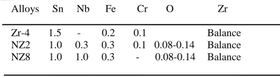
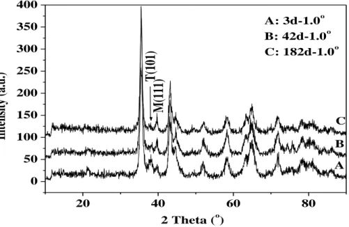
Fig. 6-1 and 6-2 show grazing incidence XRD patterns of oxide film surface for NZ2 alloy exposed to 360°C lithiated water and 400°C steam during 3 days, respectively. According to Fig, 6-3, the thicknesses measured, correspondingly to 0.2˚, 0.3˚, 0.5˚ and 1.0˚, are 0.02 nm, 0.03 nm, 43.18 nm and 143.48 nm respectively. It‘s clear that the intensity of T(101) Bragg peak for t-ZrO2 increases from the outside to the inside of oxide film. Besides,
the t-ZrO2 content in the oxide layer was found larger when processed in litiated water at
360°C than in steam at 400°C, for a common duration of 3 days. Fig. 6-4 shows the grazing incidence XRD patterns of oxide film surface of NZ2 alloy exposed to 360°C lithiated water for 3 days (curve A), 42 days(curve B) and 182 days (curve C) respectively. The grazing incidence angle is 1.0˚ and the probed thickness of oxide film is 143.48 nm. In curve A corresponding to the 3 days exposure, the intensity of the T(101) Bragg peak for t-ZrO2 is
higher than that of M(111) one corresponding to m-ZrO2 but it‘s contrary in curve B and C
corresponding to 42 days and 182 days exposure. This means that the t-ZrO2 content in the
oxide layer decreases whereas the content of m-ZrO2 increases versus the duration of
corrosion process, i.e. the t-ZrO2 transforms to m-ZrO2. Fig. 6-5 shows the grazing incidence
XRD pattern of oxide surface for NZ2 alloyexposed to 400°C steam for 3 days 42 days and 70 days. This result is consistent result with Fig. 6-4, namely, t-ZrO2 transforms to m-ZrO2
with the prolongation of corrosion time.
From the reported grazing incidence XRD analyses, the outside oxide layer of corroded NZ2 alloy was found to consist mostly of m-ZrO2, including a small amount of t-ZrO2. With
the corrosion process, t-ZrO2 transforms to m--ZrO2. The higher t-ZrO2 the content is, the
48
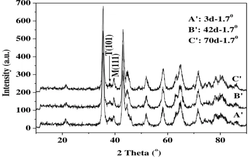
Fig. 6-6 shows the normal XRD patterns of the oxide film of NZ2 alloy exposed to 360°C lithiated water for different times. It is worth to note that the intensity of M(002) Bragg peak increases and that of T(002) one decreases with the corrosion process. T-ZrO2 changes
to m-ZrO2. This is consistent with the results of grazing incidence angle XRD. The total
integrated intensities I(hkl) of the M(-111), M(111) and T(101) were used to determine the t-ZrO2 volume fraction with respect to the total volume of zirconia using the Garvie-Nicholson
formula[144]: ) 111 ( ) 111 ( ) 101 ( ) 101 ( T M M T T I I I I f
The result of calculation as shown in Fig. 6-8, validates the above conclusions. However, the formula is likely biased because of the strong texture in the oxide film. So a better determination of the relative proportion of the t-ZrO2 and m-ZrO2 phases needs additional
experiment and analysis, e.g. texture determination. The present analysis is only a guide to appreciate the main impact of the corrosion time on the oxide layer transformation.
However, it is worth to note that in Fig. 6-6, trace 3 corresponding to (200) diffraction of c-ZrO2 phase appears when the corrosion time reaches 98 days and the oxide film thickness is
2.3μm. Then the intensity of the (200) Bragg peak increases obviously with the corrosion time (traces 4, 5, 6, 7), which corresponds to increased amount of c-ZrO2 produced in oxide layer.
Besides, from the grazing incidence XRD patterns it appears clearly that there is no c-ZrO2 on
the surface of oxide. Because the c-ZrO2 exists only inside the oxide film, this is consistent
with the result of Li [146]. C-ZrO2 nucleates during the transformation from t-ZrO2 to m-ZrO2.
We infer two kinds of transformations occur during corrosion, from tetragonal to monoclinic and from tetragonal to cubic, then to monoclinic phase. Also the existence of c-ZrO2 relates to
the addition of Nb. The stabilization mechanisms of t-ZrO2 and c-ZrO2 will be discussed in
chapter 8.
Fig.6-7 shows the same result during the oxidation of NZ2 at 400°C in steam. The t-ZrO2
transforms to m-ZrO2 versus of the prolongation of the corrosion time. It is worth to note that
the c-ZrO2 is detected in oxide film when the corrosion time is for 14 days (curve 1). Then
thickness of the oxide film is 2.1 μm. Further the content of c-ZrO2 in the film clearly
increases for longer time of oxidation (traces 2, 3, 4, 5, 6, 7). Thus, the c-ZrO2 is a transition
phase appearing between the t-ZrO2 and the m-ZrO2.
Fig. 6-8 shows the relationship between the content of t-ZrO2 in oxide films and
corrosion time of NZ2 alloy corroded at 400oC and corroded at 360oC in lithuated water. In this figure the variation of thickness of the t-ZrO2 layer is presented in relative scale,
reference to the total amount of formed oxide. It is shown that the relative value of t-ZrO2
generated in lithiated water remains more than twice that is observed under steam conditions. Moreover, the difference of the temperature, 360 to 400°C, can be considered as an additional parameter favouring less proportion of t-ZrO2 layers in the second experiment. The time
variations of the relative proportion of t-ZrO2 in both conditions (360°C lithiated water;
400°C steam) fit fairly well with experimental A.exp(- x) law. Interestingly, it is worth to note that the get the same value of -33.10-5. The rate of transformation t-ZrO2 is the same in
both experiments. As a result of initial conditions, under lithiated water at 360°C, the thickness of t-ZrO2 layer is much larger than at 400°C in steam. The c-ZrO2 phase appears in
oxide films when the corrosion transformation concerns with Nb-oxidation process, c-ZrO2
being an intermediate state between t-ZrO2 and m-ZrO2 forms. Since, the protective ZrO2
layer is found thicker under lithiated water at 360°C, the formation of c-ZrO2 that we assume
correlated with the oxidation of Nb-phase, is effectively more accentuated in steam 400°C. From the normal XRD patterns, it appears that the relative content in t-ZrO2 within the
49
the duration of corrosion process, where t-ZrO2 transforms to m-ZrO2. C-ZrO2 is a transition
phase from t-ZrO2 to m-ZrO2 transformation.
20 40 60 80 0 50 100 150 200 250 300 M(111 ) T (101) D C B A Inten si ty (a. u .) 2 Theta ( o ) A: 3d-0.2o B: 3d-0.3o C: 3d-0.5o D: 3d-1.0o
Fig. 6-1 Grazing incidence XRD patterns of the oxide film surface of NZ2 alloy exposed to 360oC lithiated water for 3d
20 40 60 80 0 200 400 600 800 1000 1200 1400 C B A M (111 ) T(1 01) Int ens it y (a. u. ) 2 Theta ( o ) A: 3d-0.3o B: 3d-0.5o C: 3d-1.0o
Fig. 6-2 Grazing incidence XRD patterns of oxide film surface of NZ2 alloy exposed to 400oC steam for 3days
50 0.2 0.4 0.6 0.8 1.0 1.2 0 200 400 600 800 1000 1200 1400 1600 1800 D etect ed thi ck ness (nm /10) Incidence angle ( o )
Fig. 6-3 Probed thickness of oxide films versus incidence angles
20 40 60 80 0 50 100 150 200 250 300 350 400 C B A
M(1
11)
T(101
)
Intens
ity
(a
.u.
)
2 Theta (o) A: 3d-1.0o B: 42d-1.0o C: 182d-1.0oFig. 6-4 Grazing angle XRD spectrum of oxide film surfaces of NZ2 alloy exposed to 360oC lithiated water for different times
51 20 40 60 80 0 100 200 300 400 500 600 700 C' B' A'
M(111)
T(101
)
Int
ensi
ty
(a.
u.
)
2 Theta (o) A': 3d-1.70 B': 42d-1.70 C': 70d-1.70Fig. 6-5 Grazing angle XRD spectrum of oxide film surfaces of NZ2 alloy exposed to 400oC steam for different times
Fig. 6-6 Normal XRD spectrum of NZ2 oxide films exposed to 360oC lithiated water for different times
52
Fig. 6-7 Normal XRD patterns of NZ2 oxide films exposed to 400oC steam for different times
Fig. 6-8 Relation of corrosion time and t-ZrO2 content in NZ2 oxide films
corroded in 360oC lithiated water and 400oC steam
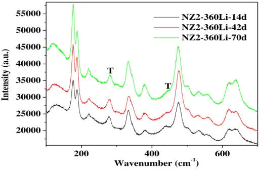
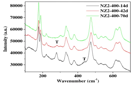
Fig. 6-9 shows the Raman spectra of oxide film for NZ2 alloy exposed to 360°C lithiated water for 14 days, 42 days and 70 days (pre-transition samples). For each spectrum, the peak positions, intensities (relative to the more intense monoclinic peak at about 177.6 cm-1), and shifts (the shift is defined here as the difference between the actual peak position and the position of the equivalent peak on powders which is showed in Tab. 6-1 [148]) are presented in