To cite this version :
Rossitto, Giacomo and Sicot, Christophe and
Ferrand, Valérie and Borée, Jacques and Harambat, Fabien
WAKE
STRUCTURE AND DRAG OF VEHICLES WITH ROUNDED
REAR EDGES
. (2015)
In: Proceedings of 50h 3AF International Conference on Applied
Aerodynamics, 29 March 2015 - 1 April 2015 (Toulouse, France)
O
pen
A
rchive
T
OULOUSE
A
rchive
O
uverte (
OATAO
)
OATAO is an open access repository that collects the work of Toulouse researchers and
makes it freely available over the web where possible.
This is an author-deposited version published in :
http://oatao.univ-toulouse.fr/
Eprints ID : 14556
Any correspondance concerning this service should be sent to the repository
administrator:
[email protected]
WAKE STRUCTURE AND DRAG OF VEHICLES WITH ROUNDED REAR EDGES
G. Rossitto (1), (2), C.Sicot (2), V.Ferrand (3),J.Borèe (2), F.Harambat (1) (1)
PSA Peugeot Citroën, 2 Route de Gisy, 78943 Vélizy-Villacoublay, France. Email: [email protected]
(2)
Institut Pprime, UPR-3346 CNRS, ENSMA, Université de Poitiers, France
(3)
ISAE Supaero, Université de Toulouse, France. INTRODUCTION
The wake structure at the rear of road vehicle is known to be of prime importance in aerodynamics performances [3]: about 30% of the total pressure drag derives from the rear end of the vehicle. While production vehicle present significant curvature at the rear end, most of fundamental aerodynamic analyses were carried out around simplified car models presenting sharp edges at the rear ([3], [5], [6]).
Since recently, very few papers addressed the question of rear edges curvature in aerodynamics performances. Thacker et al. [1] showed that rounding the edge between the end of the roof and the rear slant suppressed the separation over the rear window and resulted in 10% drag reduction. Fuller et al. [2] studied the effect on spatial stability and intensity of the pillar vortex when rounding the side rear pillars. For both of these works, the analysis was focused on the flow behaviour over the rear window: the impact of the rear end rounding on the near wake topology was not discussed.
The current study aims to understand how the use of rounded pillars with respect to sharp edges modifies the flow field (over the body surface and in the near wake) and hence the global drag. Moreover, an “academic” and an “industrial” model will be characterized to discuss the applicability of simplified models to simulate properly the sensitivity of pillars rounding.
1. EXPERIMENTAL SETUP
All the tests were conducted in the PSA Peugeot Citroën’s Eiffel wind tunnel. This wind tunnel is 52 meters long and has a test section of 2 meters high, 5,2 meters large and 6 meters long. The maximum speed is 53 m/s. Two different models
were tested: a modified Ahmed body [3], and a realistic vehicle geometry. The schematics of the models, their relevant dimensions and the coordinates system are reported in Fig 1-2. The length of the horizontal projection of the rear window (l) will be used to create non dimensional spatial coordinates. For each of them, a rounded junction between the end of the roof and the 25° rear window prevents the boundary layer from separating on the rear window. The Ahmed body will then be referred as “modified Ahmed body” in the following.
Two different rear end configurations were proposed for each model: a sharp and a rounded pillars configuration. The relative radius of curvature on the side edge of the modified Ahmed body was 10%, whereas the radius was larger and not constant for the realistic vehicle geometry. The free stream velocity was set to 40m/s, the corresponding Reynolds number based on the models length was 2.6e6.
To evaluate the aerodynamic coefficients a 6 components balance was used. The precision of the balance are 0.001 and 0.002 for Cx and Cz respectively. Wall pressure were recorded from 100 pressure probes arranged over the models connected by vinyl tubes of 0.8 mm diameter to a SCANdaq 8000 acquisition system.
Two and three components planar PIV were performed using a Quantum Big Sky Laser located outside the test section, Dantec Flowsense cameras (4M mkII with a 2024x2024 resolution and a 105mm focal lens). The size of the recorded field was 462mm*462mm. 2D PIV was performed on xz planes, while zy planes were recorded using the Stereo-PIV techniques to obtain the 3 velocity components of the flow field.
Figure 1 Modified Ahmed body
Figure 2 Realistic model
2. AERODYNAMIC LOADS
The effects of rounding the rear pillar edges on the lift and drag coefficients are reported in Tab.1. For each model, the corresponding sharp configuration is used as reference. It appears clearly that rounding the rear pillar of the Ahmed body does not modify the drag coefficient, but reduces strongly the lift coefficient. The same behaviour is recovered by the realistic model: the drag coefficient in this latter case is slightly increased by the rounded edge on the side whereas the lift experiences a significant reduction.
Table 1 Aerodynamic loads
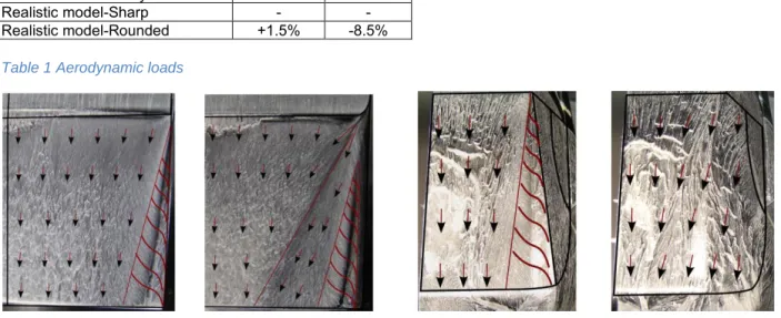
Figure 3 Oil visualization. Modified Ahmed body Left: sharp rear pillar. Right: rounded rear pillar
3. OIL VISUALIZATION
The oil visualization provides a qualitative overview of the friction lines over the rear window that can be interpreted in terms of structures present in the flow field. Usually, three main structures are present in the near wake of a fastback vehicle [3]: a separated flow region on the rear window due to the sharp edge at the end of the roof, a pillar streamwise vortex, the so called c-pillar vortex, and finally a deep separation area close to the base of the vehicle.
Fig. 3 reports the oil visualizations over the two rear ends of the modified Ahmed body. Red lines were superposed on the pictures to emphasize the main structures over the rear window.
On the left side is presented the case with sharp pillar. The footprint of the c-pillar vortex is easily detectable [4]. Outside the vortex, the flow is directed streamwise and attached overall the slanted surface. On the right side of the picture a delayed onset of the c-pillar vortex caused by the rounded edge is visible [7]. A new zone of attached flow directed inward is noticed. This transverse flow comes from the side of the model and does not roll up directly in the c-pillar vortex as for the sharp case but penetrates the rear window.
Similar interpretations can be made for the visualizations of the realistic model, Fig 4. The sharp configuration, reported on the left side of the picture, clearly demonstrates the presence of a C-pillar vortex. For the rounded configuration, the large curvature does not generate, even a delayed, c-pillar vortex. In that configuration, all the flow coming from the side of the model enters the rear window through an inward transversal attached flow.
Figure 4 Oil visualization. Realistic model. Left: sharp rear pillar. Right: rounded rear pillar
Delta Cd Delta Cl
Modified Ahmed body-Sharp - -
Modified Ahmed body-Rounded 0 -26%
Realistic model-Sharp - -
4. PRESSURE
Wall pressure distributions over the model are analysed in this section.
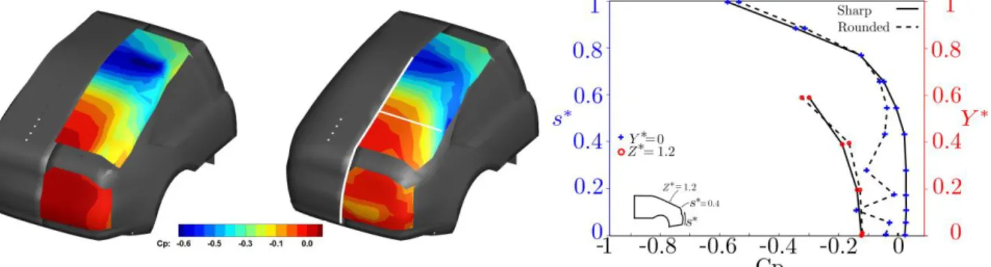
Fig 5 reports the interpolated pressure fields of the modified Ahmed body. At the end of the roof and beginning of the slanted surface, a low pressure area is observed due to the acceleration of the flow around the rounded edge, contrary to the reference Ahmed body where a sharp edge at the end of the roof generates a flow separation, [3]. For both rear ends, the flow exhibits similar behaviour in this area because of the same radius of curvature at the end of the roof.
On the side of the model with sharp edges a longitudinal vortex is observed with a fix onset at the beginning of the pillar of the model, as predicted by oil visualizations. This vortex causes an intense negative value of the pressure coefficient in the side of the rear window. On the other hand, the rounded pillar that delays the onset of the vortex (see Fig 3), allows a better pressure recovery overall the slanted surface: pressure plots on Fig. 5 (in the symmetry plane, Y*=0, and along the lateral line with Z*=1.3) exhibit higher values for the rounded pillar than for the sharp pillar case. This better pressure recovery is favourable to the drag and explains the lift reduction discussed in Tab. 1.
A close look on pressure distributions on the vertical surfaces (vehicles bases) reveals clear different intensities between the two cases. The averaged pressure coefficient over the vertical surface of the rounded case is 30% lower than the sharp one. This results in an increase of pressure drag in this area.
Fig. 6 represents pressure wall measurements for the realistic model. Due to the complexity of the side surface of the model, like for example a realistic gap between the side window and the side surface of the model, the c-pillar vortex pressure footprint is less intense than the modified Ahmed body but still present in the sharp case. The pressure distributions on the side of the rounded case confirm the absence of the c-pillar vortex. Similarly to the modified Ahmed body, the vertical surface presents a lower pressure coefficient than the sharp case. It is worth noticing that, on this vertical surface, pressure forces act purely in the drag direction which makes this region highly crucial for drag optimization. Here, the drag gain associated with the better recovery on the slanted surface is completely lost by the increase of pressure drag along the vehicle base. This
compensation justifies the zero net effect on drag
coefficient observed in Tab.1.
Figure 5 Wall pressure distributions. Modified Ahmed body. Left: Sharp rear end. Centre: rounded rear end. Right: Pressure plot over the symmetry plane(Y*=0) and for (Z*=1.3)
Figure 6 Wall pressure distributions. Realistic model. Left: Sharp rear end. Centre: rounded rear end. Right: comparison of pressure coefficient over the symmetry plane(Y*=0) and for (Z*=1.3)
5. VELOCITY FIELDS
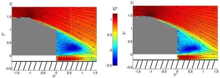
2D Particle Image Velocimetry is first applied in the symmetry plane (i.e. Y*=0) to characterise the flow behaviour on the slanted surface and the near wake area downstream the vertical base. (Fig 7 - 8).
For both configurations, it is observed that the rounding of the pillar does not affect the flow topology on the centreline of the slant surface. On the contrary, strong effects are observed in the near wake close to the vertical surface. When rounding the pillar, the length of the mean separated region in the symmetry plane is clearly shortened and the organization of the two counter-rotating inner structures is modified. For the modified Ahmed body (Fig.7), the quasi symmetrical organization observed in the sharp case is broken by a growth of the upper mean structure now closer to the vertical base. Similar trends are observed for the realistic model (Fig.8): when rounding the c-pillar the separated region is reduced by a factor two what moves the spanwise structures closer to the vertical base. This can justify the decrease in the vehicle base pressure observed in Fig 5 and 6.
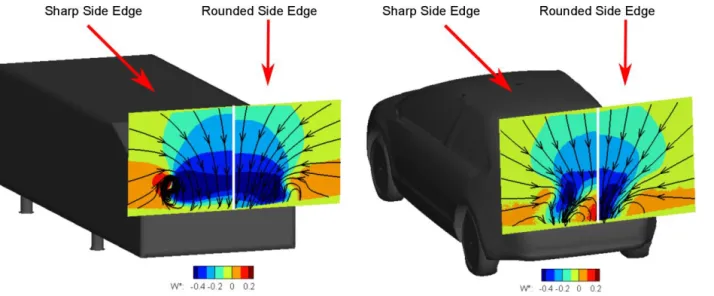
The explanation of the contraction of the mean separated region, measured in the symmetry plane, appears clearly in a 3D analysis of the near wake of these models. Fig. 9 reports cross flow streamlines in the very near wake (100mm and 30mm downstream the vehicles base for the modified Ahmed body and for the realistic model respectively) colored by the normalised vertical velocity W*. Both models are presented and, for each of them, the visualization is divided to show the sharp case on the left and the rounded case on the right. It is observed that the rounded cases exhibit stronger downwash motion that forces the mean separated region to be closer to the base. In case of sharp pillar, we saw that all the flow coming from the side tends to roll up in the C-pillar vortex that concentrates the downwash. On the other hand, for the rounded pillar case, some flow penetrates the inner region of the slanted surface without rolling (see fig 3 and 4). This extra flow rate is thought to be responsible for the observed larger downwash in the inner region of the wake and hence the topology of the mean wake.
Figure 7 PIV symmetry plane(Y*=0). Modified Ahmed body. Left: Sharp rear end. Right: rounded rear end
Figure 9 Wake visualization. Right: Modified Ahmed model. Left: realistic model.
6. CONCLUSION
Rounding the side edge of the rear end causes a reorganization of the flow field close to the model. In particular the mean separated region in the symetry plane is shortened, resulting in an increase of pressure drag on the vertical surface that compensates the gain of pressure over the slanted surface. Oil paint visualizations emphasize that adding a rounded edge on the side allows the flow that comes from the side to reach the inner part of the rear window. More investigations need to be performed to confirm the effect of the downwash induced by this transversal flow on the 3D topology of the mean wake. This works also provides a confirmation about the representativity of simplified model for the study of the effect of rounded pillars on the flow field.
This works is performed in the framework of the OpenLabFluidics@Poitiers between PSA Peugeot Citroën and Institute Pprime.
7. REFERENCES
[1] A Thacker, S Aubrun, A Leroy, P Devinant Effects of suppressing the 3D separation on the rear slant on the flow structures around an Ahmed body. Journal of Wind Engineering and Industrial Aerodynamics, 2012.
[2] J. Fuller, M.A. Passmore, The importance of rear pillar geometry on fastback wake structures, Journal of Wind Engineering and Industrial Aerodynamics, 2014.
[3] S. Ahmed, G. Ramm, G. Faitin, Some salient features of the timeaveraged ground vehicle wake, Tech. rep., Society of Automotive Engineers, Inc., Warrendale, PA (1984).
[4] J.M. Délery, Robert Legendre and Henri Werlé: toward the elucidation of three-dimensional separation. Annual review of fluid mechanics, 2001 [5] J. Davis, Wind Tunnel Investiagtion of Road Vehicle Wakes (PhD thesis). 1982. Imperial College, London
[6] S. Windsor, The effect of rear end shape on road vehicle aerodynamic drag. C427/6/031, IMechE Autotech, UK,1991
[7] J.M. Luckring, Initial experiments and analysis of blunt-edge vortex flows for VFE-2 configurations at NASA Langley, USA, Aerospace Science and Technology, 2013